1
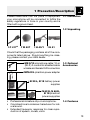
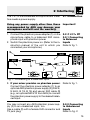
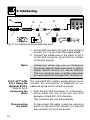
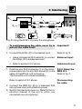
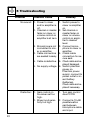
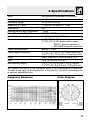
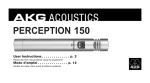
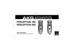
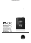
C 417 III
BEDIENUNGSHINWEISE . . . . . . . . . . . . . S. 2
Bitte vor Inbetriebnahme des Gerätes lesen!
USER INSTRUCTIONS
. . . . . . . . . . . . . . .
p. 13
Please read the manual before using the equipment!
MODE D’EMPLOI . . . . . . . . . . . . . . . . . . . . . . p. 24
Veuillez lire cette notice avant d’utiliser le système!
ISTRUZIONI PER L’USO
. . . . . . . . . . . . .
p. 35
Prima di utilizzare l’apparecchio, leggere il manuale!
MODO DE EMPLEO
. . . . . . . . . . . . . . . . . . .
p. 46
Antes de utilizar el equipo, sirvase leer el manual!
INSTRUÇÕES DE USO
. . . . . . . . . . . . . . .
Favor leia este manual antes de usar o equipamento!
p. 57
1 Precaution/Description
Please make sure that the piece of equipment
your microphone will be connected to fulfills the
safety regulations in force in your country and is
fitted with a ground lead.
1.1 Precaution
1.2 Unpacking
1 C 417III
1 W 407
1 H 40/1
1 H 41
Check that the packaging contains all of the components listed above. Should anything be missing, please contact your AKG dealer.
• MK 9/10 microphone cable: 10-m
(30-ft.) 2-conductor shielded cable
w/male and female XLR connectors
1.3 Optional
Accessories
• MPA III L phantom power adapter
• B 29 L, B 15 battery power
supplies
• N 62 E, N 66 E,
B 18 phantom
power suppplies
• Professional miniature clip-on microphone.
• Omnidirectional condenser transducer for natural sound.
• Extended frequency response for clear reproduction of speech, vocals, violin.
1.4 Features
13
1 Description
• Fastens on clothing or directly on the user's
head.
1.5 Brief
Description
The C 417III is a professional miniature condenser
clip-on microphone with an omnidirectional polar
pattern. With its wide frequency range extending
from 20 Hz to 20 kHz, low distortion at high sound
pressure levels, small size, and useful accessories, the C 417III is an ideal choice for use in any situation requiring an inconspicuous microphone
and maximum mobility for the user.
The microphone is available in two different colors
and will almost disappear when blended in with an
actor's or singer's makeup.
An external windscreen supplied with the microphone reduces wind noise when using the microphone on an open-air stage.
1.6 Versions
C 417III PP:
The C 417III is available in three versions:
• With 3-pin XLR connector with integrated adapter for 9 to 52 V universal phantom power.
• With locking mini XLR connector for use with
the B 29 L battery power supply, MPA III L
phantom power adapter, or AKG bodypack
transmitters.
• Identical to the C 417III L, except with fleshcolor cable and microphone body.
C 417III L:
C 417III PL:
14
2 Interfacing
The C 417III is a condenser microphone and therefore needs a power supply.
2.1 Introduction
Using any power supply other than those
recommended by AKG may damage your
microphone and will void the warranty.
Important!
1. Connect the phantom power adapter (1) on the
microphone cable to a balanced XLR microphone input with phantom power.
2. Switch the phantom power on. (Refer to the instruction manual of the unit to which you
connected your microphone.)
2.2 C 417III PP
2.2.1 Connecting
to Balanced
Inputs
Refer to fig. 1.
XLR
XLR
1
Phantom
2
1
3
Fig. 1: Connecting to a balanced input.
3. If your mixer provides no phantom power:
Connect the phantom power adapter (1) to an
optional AKG phantom power supply (2) (N 62 E,
N 66 E, B 18, B 15) and use an XLR cable (3)
(e.g., an optional MK 9/10 from AKG) to connect
the phantom power supply to the desired balanced input.
Refer to fig. 1.
You may connect any AKG phantom power supply (2) to an unbalanced input, too.
Use a cable (3) with a female XLR connector and
TS jack plug:
2.2.2 Connecting
to Unbalanced
Inputs
Refer to fig. 2.
15
2 Interfacing
2
XLR
5
4
Phantom
3
1
Fig. 2: Connecting to an unbalanced input.
1. On the XLR connector (4), add a wire bridge to
connect pin 1 to pin 3 and the cable shield.
2. Connect the inside wire of the cable to pin 2
on the XLR connector (4) and the tip contact
of the jack plug (5).
Note:
Unbalanced cables may pick up interference
from stray magnetic fields near power or lighting
cables, electric motors, etc. like an antenna.
This may introduce hum or similar noise when
you use a cable that is longer than 16 feet (5 m).
2.3 C 417III L/PL
2.3.1 Using the
Optional B 29 L
Refer to fig. 3.
Connecting the
cable:
The optional B 29 L battery supply allows you to
connect the microphone to balanced or unbalanced inputs with no phantom power.
Disconnecting
the cable:
To disconnect the cable, press the unlocking
button on the mini XLR connector (1) and pull
the connector (1) out of the socket.
16
1. Push the mini XLR connector (1) on the microphone cable into one of the two mini XLR
sockets on the B 29 L (2) to the stop.
The connector will lock automatically.
2 Interfacing
1
3
B 29 L
2
4
5
Fig. 3: Using the B 29 L to power the microphone.
To avoid damaging the cable, never try to
pull out the cable itself!
2. Connect the B 29 L (2) to the desired input.
Important!
Refer to fig. 3.
• Use a commercial XLR cable (3) to connect
the B 29 L (2) to a balanced input.
Balanced input:
• Refer to section 2.2.2 above.
Unbalanced input:
1. Push the mini XLR connector (1) on the microphone cable into the mini XLR socket (2) on the
cable of the MPA III L (3) to the stop.
The connector will lock automatically.
Refer to section 2.3.1 above.
2.3.2 Using the
MPA III L
Refer to fig. 4.
Disconnecting
the cable:
2. Connect the MPA III L (3) to a balanced XLR
microphone input with phantom power.
3. Switch the phantom power on. (Refer to the instruction manual of the unit to which you
connected your microphone.)
17
2 Interfacing
Mini XLR
1
MPA
Mini XLR
MPA
2
3
Phantom
3
5
4
Fig. 4: Connection diagram with MPA III L.
Refer to fig. 4.
4. If your mixer provides no phantom power:
Connect the MPA III L (3) to an optional AKG
phantom power supply (4) (N 62 E, N 66 E, B 18,
B 15) and use an XLR cable (5) (e.g., an optional
MK 9/10 from AKG) to connect the phantom
power supply (4) to the desired balanced input.
2.3.3 Connecting
to a Bodypack
Transmitter
Refer to the manual of your bodypack transmitter.
18
3 Using Your Microphone
The principal benefit of a microphone attached to
the user's clothes or integrated in their makeup is
that the microphone will maintain a constant
working distance independently of the user's movements and thus ensure a constant output level.
Also, a clip-on microphone allows the user to
move about freely and keeps their hands free.
3.1 Introduction
3.2 Lavalier
Miking
a
Fig. 5: Fixing the
microphone on the
clip (a) or tie pin (b).
b
1. Insert the cable into one of the fixing grooves
on the supplied H 40/1 clip (se fig. 5a) or on the
supplied H 41 tie pin (see fig. 5b), at a point immediately behind the microphone body.
min.
Fig. 6: Attaching
the microphone
near the user's
mouth.
2. Attach the microphone to the talker's clothes,
e.g., on the lapel, placing it as close as possible to the talker's mouth.
19
3 Using Your Microphone
Note:
The smaller the distance between the microphone and the sound source, the higher the
usable gain before feedback.
3.3 Live
Recording and
Spot Miking
1. Insert the cable into one of the fixing grooves
on the supplied H 40/1 clip (se fig. 5a) or on the
supplied H 41 tie pin (see fig. 5b).
2. Fix the microphone on a suitable part of the
stage decoration such as a flat, backdrop, curtain, etc.
3.4 Theater,
Musical, Opera
Fig. 7: Microphone
integrated in performer's makeup.
Fix the microphone on the user's head, as close
as possible to the mouth, and blend it in with the
makeup.
Many engineers place the microphone as shown
in fig. 7.
Depending on the requirements of the production
at hand, you may also attach the microphone in
different places, e.g., on the performer's forehead.
20
3 Using Your Microphone
3.5 Violin
Fig. 8: Miking up a
violin.
If the production concept does not allow for
microphones mounted on the the violin itself, you
can attach the microphone with mastic to the violinist's cheek.
Refer to fig. 8.
This method provides the following benefits:
• Since the microphone is not mounted on the
violin itself, it will not affect the sound of the instrument.
• There will be no risk of damaging the violin with
adhesive tape or similar mounting materials.
• There will be no cable that gets in the way.
4 Cleaning
To clean the microphone case, use a soft cloth
moistened with water.
21
5 Troubleshooting
Problem
Possible Cause
Remedy
No sound: 1. Power to mixer
1. Switch power to
and/or amplifier is
mixer or amplifier
off.
on.
2. Channel or master 2. Set channel or
fader on mixer, or
master fader on
volume control on
mixer or volume
amplifier is at zero.
control on amplifier to desired
level.
3. Microphone is not 3. Connect microconnected to mixphone to mixer or
er or amplifier.
amplifier.
4. Cable connectors 4. Check cable
are seated loosely.
connectors for secure seat.
5. Cable is defective. 5. Check cable and replace if damaged.
6. No supply voltage. 6. Switch phantom
power on.
Phantom power
supply: connect to
power outlet or insert battery
(batteries).
Check cable and replace if necessary.
Distortion: 1. Gain control on
the mixer set too
high.
2. Mixer input sensitivity too high.
22
1. Turn gain control
down CCW.
2. Connect a 10-dB
preattenuation
pad between
microphone cable
and input.
6 Specifications
Type:
Polar pattern:
Frequency range:
Sensitivity at 1 kHz:
Impedance:
Recommended load impedance:
Max. SPL for 1%/3% THD:
Equivalent noise level:
Power requirement:
pre-polarized condenser microphone
omnidirectional
20 Hz to 20,000 Hz
10 mV/Pa (-40 dBV re 1 V/Pa)
200
2000
118/126 dB SPL
34 dB (A) (to IEC 60268-4)
C 417III PP: 9 to 52 V universal phantom power
C 417III L/PL: B 29 L battery power supply,
MPA III L phantom adapter, or
AKG WMS bodypack transmitters
Current consumption:
approx. 2.2 mA
Cable length/Connector:
C 417III PP: 3 m (10 ft.) / 3-pin male XLR
C 417III L/PL: 1.5 m (5 ft.) / 3-pin mini XLR
Finish:
matte black (PP, L) or flesh-color (PL)
Size:
7.5 x 15 mm (0.3 x 0.6 in.)
Net/shipping weight:
C 417III PP: 8 g (0.3 oz.) / 220 g (7.8 oz.)
C 417III L/PL: 8 g (0.3 oz.) / 160 g (5.6 oz.)
This product conforms to the standards listed in the Declaration of Conformity.
To order a free copy of the Declaration of Conformity, visit http://www.akg.com
or contact [email protected].
Frequency Response
Polar Diagram
23