1
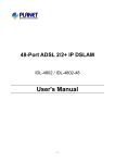
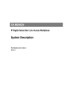
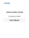
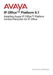
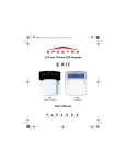
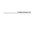
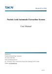
IP DSLAM
IDL-2402
Quick Installation Guide
Table of Contents
Package Contents............................................................................................. 3
Overview......................................................................................................... 4
Setup the IDL series IP DSLAM.......................................................................... 5
Safety Instruction........................................................................................ 5
Hardware Installation........................................................................................ 6
WEB Configuration............................................................................................ 9
Preparation................................................................................................. 9
Cleaning the AIR Filter.....................................................................................15
Introduction for Troubleshooting........................................................................16
Resolving Problems Indicated Through LEDs.................................................16
Resolving Problems Indicated Through Alarms...............................................16
Troubleshooting Procedures for the IDL-2402................................................16
Procedure 1 Troubleshooting for Power Up Problems......................................17
Procedure 2 Troubleshoot ADSLx Service Problems........................................18
Procedure 3 Troubleshoot POTS Service Problems..........................................18
Procedure 4 Subscriber Service Problems......................................................19
Further information..........................................................................................20
Package Contents
IDL-2402
ó IDL-2402 unit x 1
ó AC Power Cord x 1
ó CD (Containing User’s Manual, QIG) x 1
ó Quick Installation Guide x 1
ó 2-Meter Telco-50 Cable x 2
ó Console Cable x 1
ó Rack-mounting x 2
ó Screw Package x 2
If any of above items are damaged or missing, please contact your dealer
immediately.
Note
Using a power supply with a different voltage rating will damage
and void the warranty for this product.
Overview
Front Panel
The front panels of IDL series are shown below.
IDL-2402
LED Definition
LED
SYS
LED Description
Green
Normal Operation
Red
Self-test fail
Green
ALM
DSL
status
Color
Normal Operation
Red
Green
To indicate the system alarm status
On
ADSL Port is activated and linked
Off
ADSL Port is Disabled
Flash
Orange
Uplink
Green
ADSL Port is activated but not linked
On
Uplink Port connect with 100/1000Mbps Ethernet link
Off
Uplink Port connect with 10Mbps Ethernet link
On
Active
Off
Inactive
Flash
Uplink Port Transmit / receive data
Port Definition
Port
Port Description
AC PWR
AC Power cord plug-in, 100 - 240VAC is allowed.
Uplink Port
Gigabit Ethernet port.
10/100/1000Mbps, auto-negotiaiton, auto-MDI
Console Port
RS-232 port for system configuration and maintenance. Default
settings: 9600, 8, N, 1
PHONE
RJ-21 connector for connecting POTS lines.
LINE
RJ-21 connector for connecting DSL lines.
Setup the IDL series IP DSLAM
The followings are instructions for setting up PLANET IDL-2402. Refer to the
illustration and follow the simple steps below to quickly install your IP DSLAM.
Safety Instruction
The following is the safety instructions for IP DSLAM before installing.
òThe maximum operating temperature of the IP DSLAM is 65ºC. Care must
be taken to allow sufficient air circulation or space between units when the
IP DSLAM is installed inside a closed rack assembly and racks should safely
support the combined weight of all IP DSLAM.
òThe connections and equipment that supply power to the IP DSLAM should be
capable of operating safely with the maximum power requirements of the IP
DSLAM. In the event of a power overload, the supply circuits and supply wiring
should not become hazardous.
òThe AC power cord must plug into the right supply voltage. Make sure that the
supplied AC voltage is correct and stable. If the input AC voltage is over 10%
lower than the standard may cause the IP DSLAM to malfunction.
òGenerally, when installed after the final configuration, the product must comply
with the applicable safety standards and regulatory requirements of the country
in which it is installed. If necessary, consult for technical support.
òA rare condition can create a voltage potential between the earth grounds of two
or more buildings. If products installed in separate building are interconnected,
the voltage potential can cause a hazardous condition. Consult a qualified electrical consultant to determine whether or not this phenomenon exists and, if
necessary, implement corrective action before interconnecting the products. If
the equipment is to be used with telecommunications circuit, take the following
precautions:
n Never install telephone wiring during a lightning storm.
n Never install telephone jacks in wet location unless the jack is specially designed for wet location.
n Never touch un-insulated telephone wires or terminals unless the telephone
line has been disconnected at the network interface.
n Caution when installing or modifying telephone lines (other than a cordless
telephone) during an electrical storm. There is a remote risk of electric shock
from lightning.
n Do not use a telephone or other equipment connected to telephone lines to
report a gas leak in the vicinity of the leak.
Hardware Installation
The PLANET IDL-2402 is a 1.5U high box-type IP DSLAM with rack-mountable
enclosure. It can be installed in a standard 19-inch rack by using the mounting
brackets provided. Mount the shelf on the rack using the large screws provided.
The procedure to connect and wire the system is as follows.
Step 1: Ground the IP DSLAM by connecting a grounded wire (Optional).
Ground Connections
This section provides the grounding rule for the IDL-2402. All remote system sites
must be properly grounded for optimum system performance.
n In Central Office:
There should be a CO GND that is adequately grounded. If the measured resistance
from the grounding screw (on the rear panel of the DSLAM, refer to below figure)
to CO GND is less than 5 Ohm, then it can be assumed that the system is well
grounded. If the measured resistance is larger than 5 Ohm, it is recommended
to connect the grounding screw to CO GND using #14 or #12 AWG wire gauge
conductor.
n In Remote Cabinet:
The IDL-2402 should be grounded by connecting a #14 or #12 AWG conductor
between the grounding screw (on the rear panel of the DSLAM, refer to below
figure) and the earth ground or main grounding bar. The resistance between the
chassis and the grounding bar should be less than 25 Ohm.
Rear Panel Connection
IDL-2402 grounding screw on the rear panel
Step 2: Connecting the ADSL LINE and PHONE interfaces
The IDL-2402 supports 24 ports ADSL subscribers per box. There are two RJ-21
50-pin female connectors on the front panel of the system. One for ADSL line and
one for POTS interface.
To connect the subscriber lines, use cables with the RJ-21 50-pin male connectors.
When installing, just plug the end of a cable with connector into the LINE and
PHONE interface female connector on the front panel. The other end of the cable is
generally tied to the MDF (Main Distribution Frame).
The MDF Patch panel is optional of standard package.
Note
Note
Please plug-in the RJ-21 cable with connector Tenon as below
figure.
Step 3: Front Panel Connection
Power
outlet
LINE
Uplink
Console
Cable
Internet
PHONE
Switch
Workstation
192.168.1.10/24
Exchange /
PABX
MDF
IDL-PAN-48 (option)
ADSL2/2+ CPE
Front panel connection of IDL-2402
UPLINK Port: Connect to Internet by RJ-45 cable.
Console Port: Connect to PC by RS-232 console cable in order to administer your
IP DSLAM through CLI.
Step 4: Hook power cord and apply the power.
WEB Configuration
This section describes how to use Web Configuration Tool to maintain your IP
DSLAM. The IDL-2402 contains a HTTP server. You can login and configure it by
using your Web Browser.
Preparation
Before attempting to configure the IDL-2402, please ensure as below:
Set your computer’s IP with the same network mask of the router. (For example:
IDL-2402 default IP is 192.168.1.1 / 255.255.255.0)
Then you can set computer’s IP to:
192.168.1.x / 255.255.255.0. (The range for x is from 2 to 253)
Step 1: Using your WEB Browser
Open web browser and type http://192.168.1.1 in the browser’s address box.
This IP is the default IP address of IDL-2402. Press Enter.
Step 2 : Login the IDL-2402
A login page will appear. Please type your username / password and click “Sign
in”. (The default username / password is admin / admin)
After you login the IDL-2402, you will see the system information as below.
10
Step 3 : Configure the DSL PVC
Go to “Bridge Ë Interface Setup Ë ADSL PVC” setting screen, select the ADSL
port and click “Create” to apply the PVC settings.
For example, create PVC-1 to Port 1. The default VPI / VCI is 0 / 35.
11
Step 4 : Enable the ADSL Port Service
Go to “System Ë ADSL Port Service” setting screen, select the ADSL port and
Admin is “ON”. Click “Modify” to make this Port is ON.
You can see the Admin status became to ON.
12
Step 5 : Connect the ADSL2/2+ CPE to Patch Panel
Connect the ADSL2/2+ CPE to Patch Panel and configure it, the VPI / VCI value
must be the same with IDL-2402.
After finish setting, the CPE will establish the ADSL connection with IDL-2402. You
can check the connection status as below figure. The Current Status is ON.
Now the clients can access to Internet through IDL-2402.
13
Step 6 : Save the running configuration to Flash
Remember to save your running configuration to the flash, otherwise the settings
will be lost if you power-off IDL-2402.
Go to “Maintenance Ë Database” setting screen, select the “(D) Save Running
Config to Flash (System Config)”. There are two partitions on flash, select your
Partition which you want to save and click “Write Running”. The configuration will
save to the Flash.
Default Partition is Partition1.
Note
14
Cleaning the AIR Filter
For better condition of cool system, please remember to clean the Air Filter every
three months. This section provides the procedure for how to clean the Air Filter
Procedure:
Before cleaning the Air Filter, please power-off the IDL-2402 first.
You must loosen the connection of the Air Filter Panel to the DSLAM
and pull out the Air Filter before cleaning the air filter.
Note
Screw
Air Filter Panel
1 Put on the antistatic wrist strap and connect it to a grounding point.
2 Turn the screw on the Air Filter Panel counterclockwise until it loosens the
connection of the panel to the DSLAM. Remove the Air Filter Panel.
3 Pull the air filter out of the DSLAM.
4 Wash and clean the dust that on the Air Filter.
5 Slide the cleaned Air Filter into the Air Filter slot of the DSLAM.
6 Reinstall the Air Filter Panel.
15
Introduction for Troubleshooting
This chapter describes instructions for the IDL-2402 system problems. These
procedures may require the presence of technicians at remote IDL-2402 system
sites and plus an operator at PC to monitor system alarms by console during
maintenance.
Resolving Problems Indicated Through LEDs
This section describes what to do to solve problems indicated by LEDs on the
system front panel.
Problems Indicated by LEDs
LED
SYS
ALM
Activity
Problem
Action
Not lit even
though DSLAM
is powered up
There is a power up
problem with the
system.
Troubleshoot the DSLAM
for power up problems; see
troubleshooting section.
Red
Self-test failed. There
is a functional problem
with the system.
Replace the DSLAM.
Red
Major alarm set
See troubleshooting section
Red-Flash
Major and Minor alarm
set
See troubleshooting section.
Yellow
Minor alarm set
See troubleshooting section.
Resolving Problems Indicated Through Alarms
Alarms of the system are viewed through CLI and Web GUI. If an alarm indicates a
problem, please refer to troubleshooting procedures section.
Troubleshooting Procedures for the IDL-2402
When you follow a troubleshooting procedure, start from the first step of the
procedure. If the first step does not solve the problem, proceed to the next step;
keep going through the steps until the problem is solved. Use the following table to
find out the appropriate procedure for troubleshooting the listed problems.
16
List of Troubleshooting Procedures
Type of problem
Procedure
Number
IDL-2402 power up problems
Procedure 1
ADSLx service problems (POTS service is ok)
Procedure 2
POTS service problems (ADSLx service is ok)
Procedure 3
Subscriber service problems (no POTS and ADSLx service)
Procedure 4
Procedure 1 Troubleshooting for Power Up Problems
Problem indication:
ó The SYS LED on the front panel is not lit even though the DSLAM is powered up
ó Alarm that indicates a system power up problem
ó Subscribers connected to the DSLAM do not have DSL service; POTS service is
ok
Procedure:
1.Check that the power cord is connected to the power socket on the front panel,
and the other end of the cord is connected to a power outlet.
2.Check that the power feeds are connected to the DSLAM, and that power is
present on the two power feeds with correct polarity.
3.Replace the IDL-2402.
4.Contact your local distributor.
17
Procedure 2 Troubleshoot ADSLx Service Problems
Problem indication:
No ADSLx service to the affected subscribers (POTS service is ok).
Procedure:
1 If all subscribers connected to the DSLAM are affected, and the SYS LED on the
front panel is not lit, check the both end of power cords:
n If one of the power cords is not connected, power up the DSLAM by plugging
the power cord to the power socket/power outlet.
n If the power cords are both connected, follow Procedure 1 to troubleshoot
the DSLAM for power up problem
2 If all subscribers are affected, check the SYS LED on the front panel; if it is red,
replace the DSLAM.
3 If only some subscribers are affected, identify the ports that have problems.
Check that the subscribers are connected to the line interfaces properly.
4 Contact your local distributor.
Procedure 3 Troubleshoot POTS Service Problems
Problem indication:
No POTS service to the affected subscribers (ADSLx service is ok).
Procedure:
1 Check the connection of the POTS lines at the POTS connector for the DSLAM.
2 Use a bridging connector to couple the POTS and subscriber lines. If this solves
the problem, replace the DSLAM.
3 Check the condition of the POTS lines and connectors.
18
Procedure 4 Subscriber Service Problems
Problem indication:
No POTS and ADSLx service to the affected subscribers.
Procedure:
1 Check the connection of the subscriber lines and POTS lines at the subscriber
line connector for DSLAM for subscribers that do not have POTS and ADSLx
service.
n If this step results in POTS service to the affected subscribers but there is still
no ADSLx service to them, follow Procedure 2 to troubleshoot ADSLx service
problems.
n If this step results in ADSL service to the affected subscribers but there is still
no POTS service to them, follow Procedure 3 to troubleshoot POTS service
problems.
2 Use a bridging connector to couple the POTS and subscriber lines. If this results
in POTS service to the affected subscribers, contact your distributor.
3 Check the condition of the subscriber lines and connectors.
19
Further information
The above steps introduce simple installations and configurations for IDL-2402.
For further configurations and information can be found in the user’s manual CD.
Please check the user’s manual for more understandings. If you have any other
questions, please contact the local dealer where you purchasing this product.
20