1
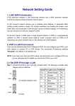
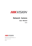
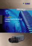
2 Mega-Pixel Fish-eye Panorama IP Camera
ICA-HM830
Quick Installation Guide
Table of Contents
Chapter 1. Introduction..................................................................................... 3
1.1 Before Installation................................................................................ 4
1.2 System Requirements........................................................................... 4
Chapter 2. Physical Description and Installation................................................... 5
2.1 ICA-HM830 Package Content................................................................. 5
2.2 ICA-HM830 Physical Details................................................................... 5
2.3 ICA-HM830 Installation......................................................................... 8
2.3.1 Wall/Ceiling Mount Installation Procedure....................................... 9
Chapter 3. Camera Windows Utility...................................................................10
3.1 Network Configuration.........................................................................10
3.2 Open the Web-based UI .....................................................................12
Further Information.........................................................................................14
Chapter 1. Introduction
Thank you for purchasing the PLANET H.264 2Mega Pixel Fish-Eye Fixed Dome
IP camera, the ICA-HM830 is include a fish-eye lens for 360° panoramic wide
angle view without blind spot. The ICA-HM830 delivers clear image through Multistreaming H.264 and Motion JPEG video up to UXGA (1600 x 1200 pixels). The
fish-eye lens with 2Mega Pixel high resolution images provides 360 degree wide
view surveillance and the panorama function with quad view enables four different
angles images to display simultaneously for monitoring and recording.
The ICA-HM830 digital Pan/Tilt and zoom function can provide users 9 different
video modes including:
ll 360° Source image
ll 360° Table view
ll 180° double broad view
ll 180° double table broad view
ll 360° source view with 3 PTZ
ll Quad view
ll 360° broad view with 2 PTZ
ll 180° source view with 3 PTZ
ll 180° broad view with 2 PTZ
Furthermore, the ICA-HM830 applies perspective correction software to eliminate
the rounding normally associated with fish-eye lenses and thus save lots of
traditional mechanical Pan/Tilt maintenance cost.
The ICA-HM830 is highly flexible to be applied in various kinds of IP surveillance
environment. It has built-in ICR (IR-cut filter Removable) for day / night
surveillance and is compatible with IEEE 802.3af PoE (Power over Ethernet) for
easy installation without concerning the outlet / socket locations. In addition, the
ICA-HM830 provides surveillance functions including DI/DO alarm, MicroSD card
support for local storage, and 2-Way audio that enables audio communication
between local and remote ICA-HM830 installed sites by connecting the external
microphone and speaker.
The ICA-HM830 is the perfect panoramic surveillance application for the hallway,
stores or offices so customers do not need to install multiple IP cameras and thus
can save lots of installation and maintenance cost. Moreover, the ICA-HM830 can
be managed by PLANET Cam Viewer 3 IP-Surveillance management software for
multi-camera video surveillance application and provides monitoring, recording and
event management functions to secure your property and life.
3
1.1 Before Installation
Before installation, please be sure to read this quick installation guide and user’s
manual (CD) carefully to complete machine installation. This guide shows how to
quick set up the IP Cameras, unless model name specified terms “IP Camera” will
be used for this model.
1.2 System Requirements
CPU
Intel® Core2 Duo E5300 2.6GHz
RAM
1 GB
Video RAM
128 MB
Display Chip
nVIDIA GeForce 8500GT or ATI Radeon HD 4350 or
above
Display Resolution
1024 x 768 24bits
Operating System
Windows 2000 SP4 / Windows XP Pro SP2 / Windows
2003 / Vista
DirectX
9.0c or above
Network
Wired Ethernet 100Base-TX
4
Chapter 2. Physical Description and Installation
2.1 ICA-HM830 Package Content
IP camera unit x 1
Power Adapter x 1
Quick Installation Guide x 1
User’s manual CD x 1
Wall Mount Kit x 1
GPIO Connector x 1
2.2 ICA-HM830 Physical Details
ICA-HM830 Front Panel:
MIC
Light sensor
Reset Button
Speaker
5
Interface
Description
Light Sensor
The Light sensor is for detect IP Camera environment
illuminant, and if IP Camera in the dark/night environment
that will let IR cut filter off for clearly night view.
MIC
The IP Camera has built-in an internal microphone. This
microphone is hidden in the pinhole located on the front
panel.
Reset Button
This button is hidden in the pinhole. Please refer to the
user’s manual for more information.
Speaker
The IP Camera has built-in an internal speaker. This
speaker is hidden in the pinhole located on the front panel.
ICA-HM830 Bottom Panel:
DC 12V
RJ-45
Audio Out
MICRO SD
MICR
DC 1
2V
RJ 45
O SD
6
Audio In
A
OUUTDIO
AU
I N DIO
GPIO
12
34
56
7
Interface
Description
Power Jack
The input power is DC 12V, 2A.
Note: ONLY use package power adapter supplied with the
internet. Otherwise, the product may be damaged.
RJ-45 LAN socket
Connect to PC or Hub/Switch.
For connect to 10Base-T Ethernet or 100Base-TX Fast
Ethernet cabling. This Ethernet port built auto-negotiaiton
protocol can detect or negotiate the transmission speed
of the network automatically. Please use CAT-5 cable to
connect the Network Camera to a 100Mbps Fast Ethernet
network switch or hub.
Note: ONLY use one power source, either from DC or from
802.3af Power over Ethernet..
MicroSD Card Slot
The IP Camera has built-in a MicroSD card slot accepts
MicroSD memory card for image / video event recording.
Audio Out
Connect a loud speaker to the IP Camera. This is for voice
alerting and two-way audio.
Audio In
Connect a microphone to the IP Camera.
GPIO
The 7 pin terminal block includes 4 input ports and 1
output ports.
Terminal block for I/O connectors:
Name
Pin
GND
1
Digital input 4
2
Digital input 3
3
Digital input 2
4
Digital input 1
5
DO_NO
6
DO_COM
7
Function
Four sets of Digital Input, DI1 until DI4; the internal
device is also photo-coupled electrical relay. In practice,
the external device can be simply an On/Off switch.
Four sets of On/Off switch can be connected as
different trigger source.
Digital output implementation; Pin6 to COM (Pin7) is a
Photo-coupled relay on Normal Open status. External
device can directly connect to the terminals. However
the current that will go through the 2 nodes must
not exceed 130mA. An external “Relay” can also be
connected to the terminals as an implementation. In
this case, current (or/and voltage) limitation is specified
by the external Relay.
7
2.3 ICA-HM830 Installation
Step 1. Prepare a PC with Ethernet link to the network
Step 2. Connect an Ethernet cable
Connect LAN port (RJ-45) of the IP Camera to a network switch. When
this switch is a PoE device, you can ignore the next step.
Note
If there has an IEEE 802.3af PoE switch in your network, you can
connect the IP Camera’s LAN cable to this PoE switch to obtain
power. The power adapter is unnecessary when IP Camera is
powered by PoE switch.
Step 3. Attach the power supply
Plug in power adapter to IP Camera and connect another end to power
outlet.
Note
Only use the power adapter supplied with IP Camera otherwise, the
product may be damaged.
Step 4. Plug Power on 100V ~ 240V
Ensure the power adaptor specification matches the power system (100 ~
110V AC or 220 ~ 240V AC) and connect the adaptor to the outlet
Step 5. Check LED status
8
The Power LED is defined to identify IP Camera status. When IP Camera
booting the LED will be flashing and while IP Camera is ready the LED will
be green.
2.3.1 Wall/Ceiling Mount Installation Procedure
Step 1. Take the wall mount bracket, put it on the target place and fix it with the
supplied screws (total of 2).
Step 2. Load the camera into the wall mount, be sure the camera are mated with
two fixed screw, and rotate the camera to lock it in position.
9
Chapter 3. Camera Windows Utility
This chapter shows how to quick set up your IP Camera. The IP Camera is with
the default settings. However to help you find the networked IP Camera quickly
the Windows utility (PLANET IPInstaller) can search the IP Cameras in the network
that shall help you to configure some basic setting before you start advanced
management and monitoring.
Please insert the bundle CD disk into your CD/DVD-ROM drive. When the welcome
web page appears, please click your IP Camera name on the IP Camera list i.e.
ICA-HM830. Then click on the utility IPInstaller to start the program.
3.1 Network Configuration
Please click “Search Network Device” button. PLANET IPInstaller will list all
networked IP Camera in the LAN. If the IP Camera doesn’t be found, you may
check whether this IP Camera is connect to network properly and press the search
button again.
1.Click the menu bar Tool > Search Network Device to search the device in the
LAN.
2.Select IP Camera with the MAC Address corresponds to the IP Camera that is to
be configured.
10
3.Double click the item to open the Property Page or click the menu bar View >
Property.
4.After filling the desired settings in the properties, click on “Set” button to
complete the configuration settings.
11
3.2 Open the Web-based UI
If IPInstaller finds IP Camera, please select the device you want to view and click
the “Open Web” button. Then you could see the video from IP Camera directly.
1.To access the Web-based UI of the selected unit, run the View > Open Web on
the menu bar.
2.After connected to IP Camera, it will prompt for User Name and Password,
please enter admin/admin to continue Web Management. Confirm the installation as it is required to view the video stream and some operations.
If difficulty is met, please refer to the following steps to establish the connection:
- The IP Camera must be installed and powered ON.
- If the IP Camera’s default IP Address (192.168.0.20) is already used by
another device, the other device must be turned OFF until the device is allocated
a new IP Address during configuration.
12
3.For the first installaiton, there will be a prompt to install the ActiveX control.
4.If the device has been configured correctly, the default Web browser will open to
the home page of the selected device.
13
Further Information
This guide is used to help you startup your Fisheye IP Camera settings. It is also
recommended to check the user manual in CD disk for more details of the system
and user configuration.
14
This page is intentionally left blank
This page is intentionally left blank