Download IPAM-4800/4824 IP DSLAM Quick Installation Guide Check Your
Transcript
Empower Broadband Access
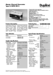
IPAM-4800/4824 IP DSLAM
Quick Installation Guide
Thank you for purchasing the IPAM-4800/4824 ADSL2/2+ IP DSLAM.
Following the Quick Installation Guide, your can quickly deploy this
device in several minutes. For getting advanced information, refer to the
user manual.
Check Your Package Contents
• IPAM-4800/4824 ADSL2/2+ IP DSLAM
• CD-ROM (containing User Manual, QIG,
EMS )
•Ethernet Cable (CAT5 UTP Straight-Through)
• AC Power Cord
• RS-232 cable
I
Using a power
supply with a
different voltage rating
will damage and void
the warranty for this
product.
Setup the IPAM-4800/4824 IP DSLAM
The IPAM-4800/4824 can be installed in a standard 19-inch rack,
by using the mounting brackets provided. Mount the shelf on the
rack using the large screws provided. The procedure to connect
and wire the system is as follows.
Rear Panel Connection
The following figure shows the rear panel connection of IPAM4800/4824:
Step 1: Ground the IPAM-4800/4824 by connecting a grounded
wire
Step 2: Connect the “Line” connector, a 50-pin centronic connector,
of IPAM-4800/4824 to CPE. Each connector supports 24
ports of ADSL/ADSL2/2+ for Data path.
Step 3: Connect the “Phone” connector, a 50-pin centronic
connector, of IPAM-4800/4824 to Exchange/PBX.
Note: (1) Patch panel and Telco cables are optional to
standard package.
(2) The 1st port of each connector comes to pair of pin
#25 and pin #50, instead of pair of pin #1 and
pin #26
Step 4: Hook power cord and apply the power.
Front Panel Connection
Connect to another IPAM-4800
Management
Station
EMS Configuration
This section shows how to prepare the system to perform basic
communication functions through Element Management System
(EMS). Perform initial configuration procedures as follows:
1.
Click the EMS button on the screen of autorun to install EMS
into your PC with Windows NT, XP or 2000.
2.
Before you start to connect to EMS, it is necessary that your
PC’s IP and IPAM-4800/4824’s IP are in the same group.
Note: Default IP address of Management port is
192.168.200.111
3.
To enable SNMP for EMS access, one needs to issue
commands below to IPAM-4800/4824 by Telnet to
management port or connecting to console port (9600, N, 8 ,1)
and then log in with default username and password of
“admin”.
a. “$create snmp comm community public rw”
b. “$create snmp host ip 192.168.200. xxx community public”,
where 192.168.200.xxx is the IP of your PC.
c. “$create snmp traphost ip 192.168.200.xxx community
public version v1”, where 192.168.200.xxx is the IP of your
PC.
4.
Launch the EMS and then log in with the “Admin” for both
user name and password. Click on
system.
5.
to enter the EMS
Add the IP address of IPAM-4800/4824 into the Agent
manager.
6.
Then the IP address and alias name will be displayed on
the Agent Desktop. Double click the IPAM-4800/4824’s IP
address in the Agent desktop.
7.
After that, you could enter the main menu of EMS for your
configuration.
Default Setting
Click on the Default Setting from the IPAM-4800/4824 main
menu. The Default Setting window will be displayed.
Configure the System
Click on the System Information from the IPAM-4800/4824
main menu in which some parameters related to the system are
available for configuration. The IPAM-4800/4824 System
Information window will appear as follows:
Configure DSL Profile
Click on the DSL from the Configuration menu.
The IPAM-4800/4824 DSL menu tree and related
windows will appear as follows:
Item
Description
Line Profile
Configuration
Alarm Profile
Configuration
Port Configuration
To browse and create ADSL
line profiles.
To browse and create ADSL
alarm profiles.
To display, modify or delete
the status of the port. It
provides the configuration of
a port’s status.
Note: the “vpi” & “vci” in “port configuration” page has to be set as same
value as CPE.
λ
λ
Line Profile Configuration window
Alarm Profile Configuration window
λ
Port Configuration window
Advanced Setting
For more detailed information about complete configuration, please
refer to the User’s Manual on the support CD
MEMO


