1
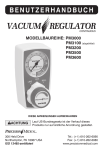
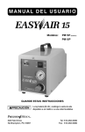
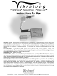
300 Held Drive Northampton Pa 18067 610.262.6090 June 10, 2015 Recommended testing for verifying device performance. Intervals of testing are to be set by the Healthcare Provider / Dealer. Table of Contents Test Requirements for the Easy Comp (PM50) ................................................................... 2 Test Requirements for the Easy Vac (PM60) ....................................................................... 2 Test Requirements for the Power Vac (PM61) .................................................................... 3 Test Requirements for the Power Vac Plus (PM63) ............................................................ 3 Test Requirements for the Easy Go Vac (PM65).................................................................. 4 Test Requirements for the MinMate Easy Neb (PM5 / PM6 / PM7)................................... 4 Test Requirements for the Easy Air (PM15F) ...................................................................... 4 Test Requirements for the Easy Air (PM15P) ...................................................................... 5 Test Requirements for 1600 series regulators. ................................................................... 5 Test Requirements for Easy Pulse Conserving Regulators (188705 & 198705). ................. 5 Test Requirements for Flowmeters ..................................................................................... 6 Test Requirements for PM106 Oxygen Supply Manifold .................................................... 6 Test Requirements for Vacuum Regulators ......................................................................... 7 Test Requirements for PM4150 Portable Oxygen Concentrator ...................................... 11 Test Requirements for PM4130 Portable Oxygen Concentrator ...................................... 12 Test Requirements for PM4351 Stationary Oxygen Concentrator.................................... 13 Test Requirements for Medical Hose Assemblies ............................................................. 14 Recommended Test Equipment ........................................................................................ 15 Page 1 of 15 Test Requirements for the Easy Comp (PM50) 1. Plug device into power source. 2. Switch power to ON. 3. Attach a calibrated pressure gauge to the outlet port. 4. Set pressure to 50 PSI 5. Verify gauge accuracy is within 2% of full scale. 6. Set pressure to maximum.(valve assembly completely Clockwise) 7. Reading on gauge must be ≥ 85 PSI 8. Power OFF device. 9. Remove pressure gauge. 10. Attach calibrated Flow gauge to valve assembly. 11. Power ON device. 12. Flow must be a ≥ 32 LPM. 13. Switch power to OFF and unplug. 14. Remove Flow gauge. Test Requirements for the Easy Vac (PM60) 1. Plug device into power source. 2. Remove suction canister assembly. 3. Attach a calibrated vacuum gauge to the device inlet port. 4. Switch power to ON. 5. Set vacuum to 15” InHg on calibrated vacuum gauge. 6. Verify device gauge accuracy is within 2% of full scale. 7. Set vacuum to maximum. (valve assembly completely Clockwise) 8. Reading on gauges must be ≥24” InHg. 9. Switch power to OFF. 10. Remove calibrated vacuum gauge. 11. Attach calibrated Flow gauge to valve assembly. 12. Switch power to ON 13. Flow must be ≥ 29 LPM 14. Switch power to OFF and unplug device. 15. Remove calibrated Flow gauge. 16. Reattach suction canister assembly. Page 2 of 15 Test Requirements for the Power Vac (PM61) 1. Plug device into power source. 2. Remove suction canister assembly. 3. Attach a calibrated vacuum gauge to the device inlet port. 4. Switch power to ON. 5. Set vacuum to 15” InHg on calibrated vacuum gauge. 6. Verify device gauge accuracy is within 2% of full scale. 7. Set vacuum to maximum. 8. Reading on gauges must be ≥24” InHg. 9. Switch power to OFF. 10. Remove calibrated vacuum gauge. 11. Attach calibrated Flow gauge to device inlet port. 12. Switch power to ON. 13. Flow must be ≥ 22 LPM 14. Switch power to OFF and unplug device. 15. Remove calibrated Flow gauge. 16. Reattach suction canister assembly. Test Requirements for the Power Vac Plus (PM63) 1. Plug device into power source. 2. Remove suction canister assembly. 3. Attach a calibrated vacuum gauge to the inlet port. 4. Turn device ON. 5. Turn white, selector knob to REG position. 6. Set vacuum to 120 mmHG (4.7” InHg) on calibrated vacuum gauge. 7. Verify device gauge accuracy is with +/- 6 mmHG (.24” InHg) 8. Set vacuum to maximum (grey knob fully clockwise). 9. Measured vacuum shall be within 9 InHg (229 mmHG) to 13 InHg (330 mmHG). 10. Switch power to OFF. 11. Remove calibrated vacuum gauge. 12. Attach calibrated Flow gauge to inlet port. 13. Switch power to ON. 14. Flow must be ≥ 17 LPM 15. Turn selector knob to INT, let device run for 2 min. 16. Ensure needle cycles intermittently between 0 and full vacuum. 17. Turn grey knob counterclockwise until gauge reaches 100 mmHg. 18. Let device run for 2 min. 19. Ensure needle cycles intermittently between 0 and 100 mmHg. 20. Turn device off. 21. Remove calibrated Flow gauge. 22. Reattach suction canister assembly. Page 3 of 15 Test Requirements for the Easy Go Vac (PM65) 1. Plug device into power source. 2. Remove suction canister assembly. 3. Attach a calibrated vacuum gauge to filter inlet port. 4. Switch power to ON. 5. Set vacuum to 15” InHg on calibrated vacuum gauge. 6. Verify device gauge accuracy is within 2% of full scale. 7. Set vacuum to maximum. (Completely Clockwise). 8. Reading on gauge must be ≥19 InHg. 9. Switch power to OFF. 10. Remove vacuum gauge. 11. Attach calibrated Flow gauge to filter inlet port. 12. Switch power to ON. 13. Flow must be ≥ 12 LPM. 14. Switch power to OFF and unplug. 15. Remove Flow gauge. 16. Reattach suction canister assembly. 17. Also verify the charger for proper operation as indicated in the User Manual. Test Requirements for the MinMate Easy Neb (PM5 / PM6 / PM7) 1. Plug device into power source. 2. Switch power to ON. 3. Attach a Westmed, Inc. Vixone ® Nebulizer Kit Part# 0210 or equivalent to the output port. 4. Attach a peace of tubing from the output of the Westmed, Inc. Vixone ® Nebulizer orifice to a calibrated Flowmeter/Gauge 5. Measured output must be 6 LPM 6. Remove Nebulizer from device. 7. Switch power to OFF and unplug Test Requirements for the Easy Air (PM15F) 1. Plug device into power source. 2. Turn regulator knob fully counterclockwise. 3. Attach a calibrated flow monitor to the outlet fitting on the PM15F. 4. Switch power to ON. 5. Turn regulator knob until flow monitor reads 5 LPM. 6. Verify reading on device flow gauge is within 1 LPM of flow monitor. 7. Turn regulator knob until flow monitor reads 10 LPM. 8. Verify reading on device flow gauge is within 1 LPM of flow monitor. 9. Turn regulator knob fully counterclockwise. 10. Switch power to OFF. 11. Remove flow monitor. Page 4 of 15 Test Requirements for the Easy Air (PM15P) 1. Plug device into power source. 2. Turn regulator knob fully counterclockwise. 3. Attach a calibrated pressure gauge to the outlet fitting on the PM15P. 4. Switch power to ON. 5. Turn regulator knob until calibrated pressure gauge is at 60 PSI 6. Verify device pressure gauge accuracy is within 2% of full scale. 7. If gauge does not reach 60 PSI, Check the device for leaks. 8. Turn regulator knob back until you reach 50 PSI. 9. Remove pressure gauge from outlet fitting and attach a flow gauge capable of reading 40 LPM. 10. Flow should be a minimum of 30.0 LPM. 11. Remove flow gauge. 12. Switch power to OFF. Test Requirements for 1600 series regulators. 1. Attach regulator to a USP Oxygen cylinder with a minimum of 500 psi 2. Ensure the regulator is in the off position. 3. Slowly open cylinder. 4. Attached a calibrated flow gauge to the outlet port of the regulator. 5. Set regulator to first setting. 6. Measured flow should be within 10cc for settings 32.25cc to 125cc, and 10% of the indicated setting of 250cc and up 7. Test all settings. 8. Return the regulator to the off position. 9. Close the cylinder and remove flow gauge. 10. Remove regulator from cylinder. Test Requirements for Easy Pulse Conserving Regulators (188705 & 198705). 1. Attach regulator to a USP Oxygen cylinder with a minimum of 500 psi 2. Ensure the regulator is in the off position. 3. Slowly open cylinder. 4. Attached a calibrated flow gauge to the outlet port of the regulator. 5. Set regulator to the 2 LPM Continuous setting. 6. Measured flow should be 10% 7. Remove the flow gauge from the outlet port of the regulator 8. Return the regulator to the off position. 9. To test the pulse settings, ensure the device triggers when an inspiratory breath is taken with a cannula connected. 10. Remove regulator from cylinder. Page 5 of 15 Test Requirements for Flowmeters 1. Inspect product for visible damage. Remove from service if any damage is found. 2. Turn control knob fully clockwise to the OFF position. 3. Connect the device to the appropriate gas source. The appropriate gas and pressure are specified on the Flow Tube. 4. Verify that the Float Ball is at the very bottom of the Flow Tube. NOTE: If the Float is not resting at the bottom of the Flow Tube, the device may be leaking; consult the Troubleshooting Guide. 5. Connect a calibrated flow measuring device to the outlet of the flowmeter. 6. Ensure the flow measuring device is set to the correct gas type.(Oxygen or Air) 7. Divide the scale into three even divisions. (Low, Middle, and High) 8. Set the flow to the Low value by aligning center of Float Ball with indicator line on the Flowtube. 9. Ensue the accuracy of the flowmeter is within the specifications stated in the user manual. 10. Repeat step 8 & 9 for the Middle & High values. Test Requirements for PM106 Oxygen Supply Manifold 1. Attach PM106 O2 Supply Manifold to a 50 psi (+/- .25 psi) oxygen source. 2. For each of the six valves, perform the following test: A. Attach one end of tubing to the tubing nipple; attach other end of tubing to a calibrated flowmeter. B. Turn Control Knob to 5 LPM setting and check the flowrate (must be 5 +/-1 LPM) C. Turn knob fully open and check the flow-rate (must be equal to or greater than 18 LPM) Page 6 of 15 Test Requirements for Vacuum Regulators Models PM3000 / PM3500 1. Connect regulator to a vacuum source capable of 21 InHg @ 100 LPM minimum. 2. Set selector on regulator to "REG" position. 3. Turn the regulator knob clockwise, then counterclockwise and ensure the gauge reaches full vacuum and also that it returns back to zero, ensuring a smooth correlation between turning the knob and the corresponding needle movement. 4. Connect a calibrated vacuum gauge to the inlet port. 5. Set the regulator gauge to 60 mmHg and ensure the calibrated vacuum gauge reading is 60 mmHg ± 4. 6. Set the regulator gauge to 140 mmHg and ensure the calibrated vacuum gauge reading is 140 mmHg ± 4. 7. For PM3000 only: Set the regulator gauge to 200 mmHg and ensure the calibrated vacuum gauge reading is 200 mmHg ± 6. 8. For PM3500 only: Set the regulator knob fully clockwise and ensure the calibrated vacuum gauge reading is 170 mmHg ± 10. 9. Disconnect the calibrated vacuum gauge. 10. Attach a calibrated flow gauge. 11. Turn knob on regulator fully clockwise. 12. Verify flow is 51 LPM. 13. Disconnect the calibrated flow gauge. 14. Turn knob on regulator fully counterclockwise. 15. Ensure gauge returns to zero. 16. If any of the above checks do not meet specifications, troubleshoot device. 17. Turn regulator OFF position. 18. Disconnect regulator from vacuum source. Page 7 of 15 Model PM3100 1. Connect regulator to a vacuum source capable of 21 InHg @ 100 LPM minimum. 2. Set the selector on the vacuum regulator to the "REG" position. 3. Turn the regulator knob clockwise, then counterclockwise and ensure the gauge reaches full vacuum and also that it returns back to zero, ensuring a smooth correlation between turning the knob and the corresponding needle movement. 4. Connect a calibrated vacuum gauge to the inlet port. 5. Set the regulator gauge to 60 mmHg and ensure the calibrated vacuum gauge reading is within +/- 5% of full scale. 6. Set the regulator gauge to 140 mmHg and ensure the calibrated vacuum gauge is within +/- 5% of full scale. 7. Set the regulator gauge to 200 mmHg and ensure the calibrated vacuum gauge reading is within +/- 5% of full scale. 8. Disconnect the calibrated vacuum gauge. 9. Attach a calibrated flow gauge. 10. Turn knob on regulator fully clockwise. 11. Verify flow is 51 LPM. 12. Set the selector on the vacuum regulator to the "LINE" position. 13. Verify flow is 55 LPM. 14. Turn regulator to the OFF position. 19. Disconnect the calibrated flow gauge. 15. Turn knob on regulator fully counterclockwise. 16. Disconnect regulator from vacuum source. 17. If any of the above checks do not meet specifications, then troubleshoot the device. Page 8 of 15 Model PM3300 1. Connect regulator to a vacuum source capable of 21 InHg @ 100 LPM minimum. 2. Set the selector on the Vacuum Regulator to the "REG" position. 3. Turn the regulator knob clockwise, then counterclockwise and ensure the gauge reaches full vacuum and also that it returns back to zero, ensuring a smooth correlation between turning the knob and the corresponding needle movement. 4. Connect a calibrated vacuum gauge to the inlet port. 5. Set the regulator gauge to 60 mm/Hg. 6. Ensure the calibrated vacuum gauge reading is within +/- 5% of full scale. 7. Set the regulator gauge to 140 mm/Hg. 8. Ensure the calibrated vacuum gauge reading is within +/- 5% of full scale. 9. Set the regulator gauge to 200 mm/Hg. 10. Ensure the calibrated vacuum gauge reading is within +/- 5% of full scale. 11. Disconnect the calibrated vacuum gauge. 12. Attach a calibrated flow gauge. 13. Turn knob on regulator fully clockwise. 14. Verify flow is 51 LPM. 15. Disconnect the calibrated flow gauge. 16. Set the regulator gauge to 180 mm/Hg. 17. Switch to the "INT" position. 18. Timing Module should engage between 6 to 10 seconds. 19. When the device clicks "ON", needle should return to 180 mm/Hg and remain steady for 14 to 18 seconds. 20. Turn Regulator to the "OFF" position. 21. Disconnect regulator from vacuum source. 22. If any of the above checks do not meet specification, troubleshoot the device and/or adjust timing. Page 9 of 15 Model PM3400 1. Connect regulator to a vacuum source capable of 21 InHg @ 100 LPM minimum. 2. Connect a calibrated vacuum gauge to the inlet port. 3. Set the selector on the vacuum regulator to the "REG" position. 4. Turn the regulator knob clockwise, then counterclockwise and ensure the gauge reaches full vacuum and also that it returns back to zero, ensuring a smooth correlation between turning the knob and the corresponding needle movement. 5. Set the regulator gauge to 60 mmHg (8 KPa). 6. Ensure the calibrated vacuum gauge reading is within +/- 5% of full scale. 7. Set the regulator gauge to 140 mmHg (18-20 KPa). 8. Ensure the calibrated vacuum gauge reading is within +/- 5% of full scale. 9. Turn the Vac device up to maximum (fully clockwise); verify max vac is 170 mmHg ±10. 10. Disconnect the calibrated vacuum gauge and connect a calibrated flow gauge. 11. Verify flow is 50 LPM. 12. Disconnect the calibrated flow gauge. 13. Place the device in the "REG" position and set the needle to 120 mmHg. 14. Switch to the "INT" position. 15. Timing Module should engage between 6 to 10 seconds. 16. When the device clicks "ON", needle should return to 120 mmHg and remain steady for 14 to 18 seconds. 17. Turn Regulator to the "OFF" position. 18. Disconnect regulator from vacuum source. 19. If any of the above checks do not meet specification, troubleshoot the device and/or adjust timing. Page 10 of 15 Test Requirements for PM4150 Portable Oxygen Concentrator Checking the Oxygen Purity Put the EasyPulse POC in Test Mode 1. Ensure the POC is not plugged in and an external battery is not connected. 2. Ensure the POC Selector Knob is in the off position for at least 15 seconds before attempting to put in to the test mode. 3. Like a combination lock, turn Selector Knob to: 5, then 1, then 3, then off. 4. Turn Selector Knob to any flow setting. The device will continuously pulse. 5. The alarm LED on the front will blink yellow and red while in test mode. (Steps 3 & 4 must be completed within 8 seconds) 6. Attach external power source to the POC if needed. 7. In this mode, you can go to any flow setting and test oxygen purity. The EasyPulse POC will pulse as if it was attached to a simulator breathing 20 breaths per minute. O2 Concentration should be ≥ 87% @ 5 lpm setting within 4 to 6 minutes. 8. To return EasyPulse POC to normal operation, turn Selector Knob to off position. Once the device is turned to the off position, you will need to go through the above steps above to get the device back into the test mode. Page 11 of 15 Test Requirements for PM4130 Portable Oxygen Concentrator Checking the Oxygen Purity Put the EasyPulse POC in Test Mode 1. Ensure the POC is not plugged in and an external battery is not connected. 2. Ensure the POC Selector Knob is in the off position for at least 15 seconds before attempting to put in to the test mode. 3. Like a combination lock, turn Selector Knob to: 3, then 1, then 2, then off. 4. Turn Selector Knob to any flow setting. The device will continuously pulse. 5. The alarm LED on the front will blink yellow and red while in test mode. (Steps 3 & 4 must be completed within 8 seconds) 6. Attach external power source to the POC if needed. 7. In this mode, you can go to any flow setting and test oxygen purity. The EasyPulse POC will pulse as if it was attached to a simulator breathing 20 breaths per minute. O2 Concentration should be ≥ 87% @ 5 lpm setting within 4 to 6 minutes. 8. To return EasyPulse POC to normal operation, turn Selector Knob to off position. Once the device is turned to the off position, you will need to go through the above steps above to get the device back into the test mode. Page 12 of 15 Test Requirements for PM4351 Stationary Oxygen Concentrator 1. Ensure Device Power Switch is in off position “O”. 2. Plug Device into a 120 VAC source. 3. Turn Dial Flowmeter on Device to Setting 5. 4. Power on (I) Device. 4.1. When powering on Device, verify a momentary audible “beep” is heard and that the Green, Yellow and Red LEDs on Front Panel illuminate for 1 second and then only the Green LED remains illuminated. 5. Verify Fan is pulling air into the Device by placing your hand under the Base and verifying you feel air moving. 6. Allow Device to run a minimum of 3 minutes. 7. Attach hose from a calibrated oxygen flow monitor to outlet of flowmeter. 8. Verify all flow settings are within the specified tolerance. 9. Return the Flow Selector back to setting 5. 10. Disconnect flow monitor from the Device outlet and connect a calibrated Oxygen Monitor/Analyzer. 11. Verify O2 concentration is within the specified tolerance. 12. Disconnect the Oxygen Monitor/Analyzer from the Device outlet. 13. Unplug the Device from 120 VAC source while Power Switch is still in on (I) position. 14. Verify a continuous audible alarm is heard. 15. Turn The Device off by pressing Power Switch to off (O) position. 16. The continuous audible alarm should stop. *Altitude Up to 6,500 ft 6,501 - 10,000 ft Flow Tolerance (l/min) Oxygen % ± 200 ml settings 0.5 -1.5 ± 10% of settings 2 - 5 87 - 95 % ± 200 ml settings 0.5 ± 20% of settings 1 - 5 85 - 90 % Page 13 of 15 Test Requirements for Medical Hose Assemblies Part 1 1. Using approperate fitting(s), block off one end of Hose Assembly to be tested as illustrated. 2. Using approperate fitting(s), connect opposite end of Hose Assembly to a 3-Way valve as illustrated. 3. Connect a pressure gauge capable of reading 50 PSIG to port of 3Way valve as illustrated. 4. Connect the remaining port of the 3Way valve to a 50 PSIG Air presssue source as illustrated. 5. Turn on Air pressure source. 6. Open 3-Way valve to pressurize the hose assembly. 7. Apply Oxy Tec, or equivalent, Leak Detector to each end of Hose Assembly and ensure that NO bubbles are evident. Part 2 1. With the Hose Assembly still pressurized, turn the 3-Way knob the opposite direction as illustrated. 2. Observe pressure gauge for 10 to 15 seconds. 3. The pressure should remain stable. (no loss) a. If the pressure drops and/or bubbles are detected, the Hose Assembly fails the leak test. 4. Disconnect \ turn off Air pressure source. 5. Remove fitting(s) connecting the Hose Assembly to the 3-Way valve. 6. Remove fitting(s) blocking opposite end of Hose Assembly. Page 14 of 15 Recommended Test Equipment Flow Gauge/Monitor The TSI Model 4040 Mass Flowmeter can be used for a multitude of gas flow measurement applications. Whether measuring gas flows in a laboratory or manufacturing setting, TSI general-purpose mass flowmeters provide accurate results with multiple data output options. The display versions come complete with accessories making setup and operation fast and convenient. www.tsi.com Vacuum Gauge Wika 332.34 series industrial quality precision test gauges measure Vacuum within +/- 0.25% of span. Solid front, blow-out-back rugged thermoplastic case meets safety requirements of ASME B40.100. Internal parts and process connection are made of 316 stainless steel, providing excellent corrosion resistance. The dial has a reflective mirrored band with a micrometer adjustable knife-edge pointer for easy-to-read accurate pressure readings. www.wika.com Pressure Gauge Wika 4" Inspector's test gauges are the logical choice for precision pressure testing and convenient field calibrations. High precision accuracy of 0.25% of span meets rigid ASME B40.1 Grade 3A quality standards. The mirrored band on the dial and the knife-edge pointer make it easy to take accurate pressure readings. www.wika.com END Page 15 of 15