1
®
E stablished 1981
Advanced Test Equipment Rentals
www.atecorp.com 800-404-ATEC (2832)
Precision Power
Analysis from Voltech
4>r
00 A
. . r,
" .B V
J U J J ~1
6 .012 R
©
®
'80kVp •9 96 .8 Y
.e 0
[~
II t j'13 [AU
0
!
u 0©
B C3
C3 d tM C3
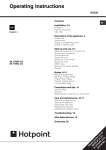
V
oltech launched the world's
Analyser was the first to use DSP
first commercially available
(Digital Signal Processor)
digital power analyser, the
technology . Today, the
PM1 000, in 1987 and the world's
PM3000ACE and PM3300CE offer
first digital three phase power
power measurement professionals
analyser, the PM3000, in 1989 . In
an unrivalled combination of
1993 the PM3000A Power
versatility and accuracy .
• Single and Three Phase Models
• Intuitive front panel or Windows software operation
• High 0 .05% Basic Accuracy
• Wide bandwidth measurements, DC and 0 .1 Hz to 1 MHz
M
a
Factors, Frequency and Inrush Current .
-
c a = aoooo "~' °% u
oco
G
013
C t~
• Measures W, V, A, VA, Var, Power Factor, Cos, Vpk, Apk, Crest
C
•
U
C
• Harmonics of V, A, (incl . Phase) and W to the 99th . THD .
• Integrator for W-hr, VA-hr, A-hr, VA-hr, Average and target PF
• Crest factors up to 20
• Accurate on distorted waveforms and at low power factors
• VPAS PC software for setup, data storage and handling
• IEC555/1000-3 Windows software for full or pre-compliance testing
• Versatile Graphics Display (PM3300)
• On Board Thermal Printer (PM3300)
• All interfaces fitted as standard .
(See back page for model options)
• All instruments supplied with test leads, user manual and certificate
of calibration and conformance traceable to international standards .
• Range of accessories includes current clamps and transformers,
PS1000 switch for inrush measurements and Ballast CT for electronic
ballast testing.
PM
.wmasx rowrn ,,w .~rrrn
nr
CHI
r,
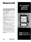
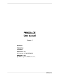
PM3000A/PM3300
Functional Block Diagram
Monotonic Analog to Digital Converters
Powerful Single DSP is placed centrally and
(A/D) are triggered simultaneously by the
Digital Signal Processor (DSP) to ensure
controls the A/D sample rate to a maximum
of 330kHz . Computes using synchronous
ultimate phase accuracy .
raw data points (not RMS values) from all
channels for improved inter-phase
information and calculation of neutral
quantities .
Analyser ranges by
switching the gain
of precision, low
AID
00.
. No
Keyboard
Vtoniseamplfr
relay switching
provides ruggedness
Alu
and reliability.
A10
E',
AID
A
DSP
Display
Processor
AID
Single shunt design
guarantees frequency
and phase accuracy
IEEE488
RS232
does not change with
different ranges .
RAM
-1
Printer
Chart Recorder
Other Interfaces
AID
3 voltage and 3 current
channels isolated from
M
each other and ground .
tom,
AID -
Careful mechanical
design ensures excellent
Dedicated
Digital signal isolation
technique - eradicates
distortion errors found
rejection of Common
Mode Voltages .
microprocessor
supervises
measurements and
transfers information
in analog designs .
to the interfaces .
Backpanel interface
Torque and Speed (PM3300
and PM :3000ACE model -001) .
Direct input to
1400Vrms,2000Vpk
External trigger and
frequency inputs .
Universal line input
92 to 26 .-,AC, 48 to
440 H z .
i
CH 3
30ARMS
(200Apk)
extended bs
choice of
external
transducers .
r-- { CH 2
HI
r-
•-
iV
~~
-LO
Voltseh
201WAd" LM
~L
L --_
•
HI
r,
i
0
~
A
HI
-LO
LO
EXTA
•- EXT
•
i AUXILIARY INPUTS
HI
N
i V
_76
Fe- HI
®-LO
EX
1'CH 1 ,-~
•
\
_
•
1 1~ --Om
• • RS232,
• IEEE488
L
r•
HI
EEE~- 488
-~®-LO
5
R~
EXTA
LID- EXT L
EXT
PAFA__E_=F`,TE ;
ANALOG-ALARMS
i
THIS EOUIPMENT MUST BE EARTHED . CONNECT TO POWER SOURCE WITS GRWNO
® CONTACT BEFORE MAKING ANY CONNECTIONS TO MEASUREING OR CONTROL CIRCUIT
External shunt input for
current transducers with
a voltage output .
Complies with
international safety
and EMC standards .
Connect directly to a
parallel printer for
manual or automatic
printing or results
Analog and chart
recorder outputs .
I
iys
1 L~1
t
a
I
s
Measurements
aaer©
..
q 3 0
N
T
d
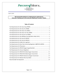
he versatile PM3000ACE and PM3300CE can be quickly configured to make reliable,
a( curate measurements in even the most demanding power electronics applications .
Illustrated here by the VPAS software, all features except lEC1000-3 are also available
13
~..t
U
V
with a few simple keystrokes upon the front panel .
oeeBEl
:J
oaao
-
ootna
to 0
\ ;11 .,11
•
Op.r.en9uo •.
Unique PWM Motor Drive mode locks onto wide range of fundamental
frequencies from 0 .1 HT to 1 kHz . Total W, V, A etc . measurements are made to
58 H'
® N:
uDllna
Trnndnrm4l
the full 1 MHz bandwidth . No data is lost .
.
.w<•noP
•
`'" IA
Ballas t mode quickly sets up the analyser for measurements on the waveforms
found in electronic ballasts and ultrasonics .
•
Power transformer test mode displays corrected
power and k factors to IEC76 and IEEECS7 .
r nl
II'V• .J,
•
~. ~.
0o
~ ON
Cdr
~ IndrA
.d.N
Scale factors for current and voltage
SNmV
transformers/transducers and torque/speed inputs are
.
M 104*.
1 Irlw
quickly entered and stored .
∎ Vd<r
y
Iv+ •
•
Over 200 further functions and features quickly
accessible .
41W
I"Q•
I- <l
~ .41 V
414V
I ~
.~
•
M I
•
•
I nrn,nnlP,
WW
VA
VA •
V<bNus
WIS
-I-
~Inrm,rn,r .
~n~r,r~ .
E_1
CNw_II
O..wr 7
V4, NA.r.N.•
Y.b N..w•
w . . r rmiini
, n a"Dn4 •
~OY41w .
`.d .
Ate• 4r 1A<4 .
three phases plus SUM
On
<r
WIN
and neutral .
I u I ~ ,~ _
5iri1+•
•
u
Harmonics of Volts and
S~I
Amps including accurate
1 1 -1 .1 .1 1
• 1~
rv Va
Vs. c
Results available for all
~ nr. .r n, Y
harmonic phase for
Vim' TOM
computation of Watts
Ay IND
Imo_
•000<_w0
I'RNS
harmonics and inverse
DFT waveform (VPAS) .
W n s
E~1
•
shown in software and
~
•
Cycle by cycle capture
~~~
< ..Ay,..
MS
S I T-1
harmonic barcharts
CF13
TcwN
"
Waveform datalog and
on PM3300 .
Mew
-~
4140 290 :114
41ND as aaa awls
4ti
w~ S<
R, h,
dI ur N...J
7W "111 1.s as
%'.a W.0 mm Ina van
40 Will 0 140 40 71 am
VO 11711
AR .1715 Ira* 14M
14
401
am
74- V
••4•4•I aln
. 4011
=
In .4r« D17 40AV.ft•q
< 7M< _--
"
+~'
.wr,
of RMS data for start-up
4
and other transient
_
_ - lunbunul Ruub
al. oD
1
WA GH 1071
Virl a
wrw
.n waa 40.1 am
conditions .
•
r.~r.. .<.•r Alr ,
a .Iaa •d n...
. up .
401:
Timed datalog of results .
rrr< < ..r 4< a
st.")••M :.3 07"
11a11•-aH.4 • 1 -4.4171 I
114071. 10.w1. 1 4. :Ia 1
>i~ OIImm011
w4,hSrV
•
0000
Ir emu"'
L
IEC555 / IEC1000-3
Harmonics and Flicker
_"
2
6 7168
1
*
.6UnA
nkn .N5
..
527M.n
9b .
41M
14.
623768/y .
2
wM u68 66868
•
75.•. , 'V .
N5
..
•
68 06.
21" 37M
N5
. .B
10, 25.224
115117681•6
8
2'S1M
1213668N5
.*N5
...
13
5545M
M 26.268
L
095—
7Nar
I5
425•6
8 11"
16mA
I6
0 7068
N5
. . N5
..
11
45'68
15
1168
.68
16Non.N5
..
.9
01 l5M
9,681168
'-- r'7tA
ly.
N5
..
411111
*Full compliance testing to IEC with - 002 model,
,
impedance network and AC source .
22
106.16
N5
..
s
S
•
Pre-compliance stand-alone with any model .
•
•
Traceable, certified accuracy .
Current and voltage harmonics, Power and Power Factor
measured throughout a test .
•
Windows software with diagnostic features .
•
Fluctuating harmonics :
se.
11hommmr
• Waveform display and Class D checking.
• Current and voltage harmonics, Power and Power
Factor measured throughout a test .
• Fluctuating limits calculated for each 16 cycle block .
• Playback of individual harmonic over time showing
Power and fluctuating limits .
• Normalised worst case bar-graph shows margin of
safety.
Flicker
:
6 . . .. ~°'°-
-_•-
-
-
• Short term (Pst) and long term (Pit) flicker, d(c),
d(max), and d(t).
• Instantaneous Flicker Sensation (IFS) displayed
continuously during test.
Connection Details
3
0
:"Lnue
I[-'
Select
l
b
in
O)JI'LO I
JrA
Three-phase. Three-wue
(2 wonmeser meelodj
Three
M.
e
~7
Source
,k'.
X1.
Three
Pha'.
Load
®
®
Mxz
X. 'L
Three
Three
Phase
Phase
Sauce
Load
Select
0
), .A
0 0 0
three-phase. four-wire .
(3 watrrnetee -'half
1
'91
Three
Phase
®7
Three
Select
LS:I
Source
Load
MOM
II
Specification
S
=ieyaeC
i
s~
aee®e
B U013 B
rsaea
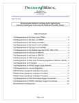
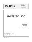
calculating total errors .
The graphs below show the total maximum
errors of the PM3000A at 11 5V rms and 5A
rms as a percentage of the reading .
pec ifications can often be confusing
and time consuming to interpret for use
in real life applications . The effects due to
frequency, power factor and instrument
range must all be considered ,,hen
~aao
00
N .B . All specifications valid for one year from calibration and at
23°C t5°C :
Maximum Voltage and Current Error Vs Frequency
-
I I -)% rills
- 5A mis
Volts 45 to 450Hz
±0 .05"' rdg t0 .05° ; mg
Amps 4 to 450Hz
±0 .05'io rdg t0 .05"„mq
±100NA
Maximum Power Error Vs Frequency
aoooo
c
0~~1
o~O
30
Watts 4 -) to •1 5uHz, 10 = I
±i\ rdg x V error
±V rdg x A error
11 .04 rdg
25
X
a
a
r
20
m
e
04
W
15
K
X
f"
01 .
10
U
I U{JU
7UU
5
0
01
1
10
1000
100
10000
100000
1000000
Maximum Power Error Vs Power Factor
Watts 4 i t,1 4SuHz
± A rdg x V error x PF
±V rdg x A error x PF
.04''F)",, rdg
±(0
05
0.1
1
-- ikill ,
001
Specification
Voltage Channels
Ranges
0.5V to 2110OVpk 11400%
Overload withstand
5000Vpk for I second
Input Impedance
I M83 and IOpF
12 ranges in 1-2-5 sequence
Effect of Common Mode Voltage:
i l01%' •n n at 60HI
Less than 20mV
100V
Less than 580 iV
nro al
100kHz
V P%1311,1n1i-A( -,xu and pr Bull( I
Current Channels
Internal shunt ranges
0.05A to 200Apk 130Am
External shunt ranges
6,2500rms to 2.5Vpk
Overload withstand
200A ,ms for I second
Internal Impedance
0.01250
(0.003512 PM3000ACE-002 and PM33000EI
External Impedance
1 Mil in parallel IOpF
)20kL1 in parallel 33pF PM30f10ACE-002 and PM33000E
Effect of Common Mode %ollages:
I r"JOC
ar Nil tz
1-1
I ixl\' rm,
at
Less than 2nrA
100kHz
Less than 20mA
Basic Accuracy
V
A
If1P-rd ;d
JS .-ng
N'
1001° .rdg
00i°„m:a
VAr
iArdgP--
If,
±V ,dg x A e •ro• x PF
rdg x A error x l I-PFF:"
"nor \ (I-Pr= ''
Additional maximum errors, PM3000ACE and PM3000ACE-001
45Hz to 450Hz
±100µq
IX
_1--\ ,
11.1 Hz to 250kHz
II i
±)0.04/P1)% rdg
±10.04 / Il-PF2)° t)% rdg
±0 .050 . rdg
± (kHz x 0.04% rdg tl OOpA
±)kHz x 0 .04%NH rdg
:)kHz x 0 .04 / Il-PF 2 I° 3 )% rdg
±0 .05% rdg ±IkHz + 2501
x ±0 .02% rdg ±l OOpA
±(lkHz +750) x 0.01/PFI% rdg
±ikHz + 750) x 10 .01 / Il-PFI° si % rdg
±100pA
±)0.04/PF)% rdg
±10.04 / (1-P1210 )% rdg
:(ikliz +1250) x 0 .Ot/PF)% rdg
.)kHz + 12501 x 10 .01 / II-PF = I° '1% rdg
n201iA .
rdg ±002% rdg per kHz
250kHz to 500kHz d l u i rdg x0 .02% rdg per kHz
Additional maximum errors, PM3000ACE-002 and PM3300
45Hz to 450Hz
DC
rdg ±0 21. rdg per kHz ±0 .05% rdg
±)kHz x 0.OhIPF)% rdg
t800pA •
.a 0 ;' •.
0.1 Hz to 250kHZ
±IkHz x 0.06 / )I-PF
2 1° s l% rdg
± kHz x 0.08% rdg ±t OOpA
250kHz to 500kHz
x0.05±,
rdg x0 .02% rdg per kHz
10 .05% rdg ±1kHz + 250)
x 0.04% rdg ±100pA
VA
nA rdg x V error x ±V rdg x A errs
Harmonics
Current PM3000ACE and PM300uACE-001
Fundamental or lit Harmonic
Voltage
.1'.rdgt0.1%tog
t0
ikHzx0.021%rdg
Harmonics 2 to 99
tlkHz x 0.05) + 0.111% of fundamenaa
T HO
±i (kHz x 0.01) + 0.2)1%
Bandwidth
Other
-r .I
io
Current PM3000ACE-002 and PM33000E
rng .:Hz,r 0'" rdg±100uA
-uP r, :L1
t11-10
0 .1 HZ to I MHZ
Functions
Power Factor (PF)
± 0.1102 t)kHz x 0.001/PFl
Crest Factor
Voltage
Current
Inrush Current
1 .000 to 19.999
10 .10% rdg 10.05/ rng x0.02
±0 .10% rdg A.011 mg x0.01
0 .1A to 200Apk (with scaling to 200MAI
2 .0% rng
Impedance
0 .0001 Q to 9 .999,W)
45Hz to 450Hz
0 .5% rdg
0.1 Hz to 500kHZ
x0 .5% rdg ±IkHz x 0 .05/PFI% rdg
Auxiliary Inputs A and B
rTorque and Speedl
0 to 1 V and 0 to 10V ranges, software selectable
±0 .5% rdg ±0 .5% mg
External Integrator Trigger
Close switch to trigger. Max+ current <SmA
External Frequent, Input
4V lo2OV p-p; 0.1 Hz 6MHz
Analog Outputs
8 outouts. 0 to +5V dc : 5mA max .
Environment
Temperature
5° to +40°C operating
Humidity
10% to 80% RH non-condensing
Dielectric Strength
Inputs to Case or Power Supply
4kv AC 50/60Hz for I minute
Input to Input
2kv AC 50/6OHz for I minute
Power Supply to Case
2 9kV DC for I minute
Power Requirement
90 - 264V ac 481o 440Hz
PVI3000ACF
30W. 60VA max .
PM33011ACE
50W. 75VA max .
Rdg = displayed reading
'DC Specification after performing a manual zero .
roll = analyser range
kHz = measured frequency in kHz
rng oil) I,xII (f MI°,,rdg
0
D
Specification
S
aeto®o
13 E3
EDte®®
C3 a
ao
specifications can often he confusing
calculating total errors .
and time consuming to interpret for use
The graphs below show the total maximum
in real life applications . The effects due to
errors of the PM3000A at 11 5V rms and 5A
frequency, power factor and instrument
rnis as a percentage of the reading .
range must all be considered when
O®na
o® .
N .B . All specifications valid for one year from calibration and at 23°C ±5°C :
Maximum Voltage and Current Error Vs Frequency
-
10
1 1 -)V rms
9
Sit rms
Volts 45 to 450Hz
±0 .05% rdg ±0 .05%mg
e
Amps 45 to 450Hz
±0 .05`% rdg ±0 .05%mg
±10OpA
1
8
F
7
A
o
8
`o
w 02
5
y
s
4
01
0
500
1000
3
2
1
0
01
1
10
100
1000
10000
100000
1000000
Maximum Power Error Vs Frequency
0
,.
coo
Q
D
aoooo
Y
eea~u
p00
Watts 45 to 4501
±A rdg x V error
±V rdg x A error
±0 .04°' rdg
30
lz, PF = 1
1
25
p
$
04
-
a
m
15
x
"
0 1
10
u
°uu
1uuu
5
0
0 .1
1
10
100
1000
Maximum Power Error Vs Power Factor
Watts 45 to 4501 lz
±A rdg x V error x PF
±V rdg x A error x PF
±(0 .04/PF)"S, r(Ig,
5
4.5
10000
100000
1000000
Ordering Information
Products
P,titi000ACL Standard
PM3000ACE-001 Fitted with lorque and Speed Inputs
PM3000ACE-002 Single Phase for full compliance IEC555 / 1000-3 Testing
E]®OB
A
PM3000ACE-002 Three Phase for full compliance IEC555 / 1000-3 Testing
a
PM3300CE Three Phase with Torque and Speed + compliance IEC555 / 1000-3 Testing
E3 El
coao
IMP555 Impedance Network for full compliance IEC555 / 1000-3 Testing
Accessories
etnaQ
ao
PS1000 Switch for Inrush Testing
Ballast CT for I IF Electronic Lighting Applications
CL 100 100 :1 Clamp On Current Transformer
CL 1000 1000 : Clamp On Current Transformer
CT1000 Precision Dual Ratio 1000/100 :1 Current Transformer
Rack `counting Kit VPN97-005
Papc - rolls for PM3300 VPN75-021
PC Software
WAS General Purpose Software
IEC .5 .55 / 1000-3 Software .
Whilst every care has been taken in compiling the intormation in this publication, Voltech Instruments cannot
accept legal liability for any inaccuracies . Voltech Instruments has an intensive programme of design and
development which may alter product specification . Voltech Instruments reserves the right to alter specification
without notice and whenever necessary to ensure optimum performance from its product range .
Copyright Voltech Instruments 1998 . All rights reserved .
Voltech's customers include major household names and leading industrial companies in Asia,
Europe and the USA . Our world-wide network of trained distributors provides first level
applications support and product service . Our main offices and top level customer support
facilities are based in the USA and UK .
Voltech USA . Morrisville . North Carolina .
Transformer Tester Manufacturing and
Support .
Voltech UK Abingdon, Oxfordshire .
Power Analyser Manufacturing and
Support .
Corporate Administration, Engineering
and Marketing .
Distributed bv :
R
ISO 9001
02 1
CE
Voltech Instruments Inc
Voltech Instruments Limited
1100 Perimeter Park Drive
Morrisville
NC 27560 USA
Tel : +I 919 461 1701
Fax : + 1 919 461 1709
E mail : sales@voltech .co m
65 Milton Park Abingdon
Oxfordshire
OX 14 4RX UK
Tel : +44 1235 834555
Fax : +44 1235 835016
E mail : sales@voltech .co.u k
http ://www.voltech .co m
O
T\t
l t
c
THE WORLD'S MOST POPULAR POWER ANALYSERS
VPN 86-008/04