1
I-8048
User’s Manual
Warranty
All products manufactured by ICP DAS are warranted against
defective materials for a period of one year from the date of delivery to the
original purchaser.
Warning
ICP DAS assumes no liability for damages consequent to the use of
this product. ICP DAS reserves the right to change this manual at any time
without notice. The information furnished by ICP DAS is believed to be
accurate and reliable. However, no responsibility is assumed by ICP DAS
for its use, nor for any infringements of patents or other rights of third
parties resulting from its use.
Copyright
Copyright 2004 by ICP DAS. All rights are reserved.
Trademark
The names used for identification only maybe registered trademarks
of their respective companies.
I-8048 Hardware User’s Manual, Mar. 2005, Rev. 1.0
------
1
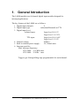
1.
General Introduction
The I-8048 module is an 8-channel digital input module designed for
interrupt applications.
The key features of the I-8048 are as follows:
1. Digital input channels:
8
2. Digital input type:
isolated(differential) or TTL
3. Digital input level:
isolated input:
Logic level 0: 0~1V
Logic level 1: 4~30V
TTL input:
Logic level 0: 0~0.8V
Logic level 1: 2~5V
4. Isolated voltage:
2000VDC
5. Built-in isolated power supply:
5V, 200mA max.
6. Interrupt specifics
Max. interrupt frequency:
CPU 40M: 15.8 KHz max.
CPU 80M: 35 KHz max.
Trigger type: Rising/falling edge programmable for each channel.
I-8048 Hardware User’s Manual, Mar. 2005, Rev. 1.0
------
2
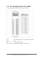
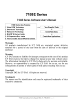
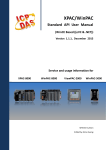
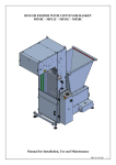
1.1. Pin Assignment for the I-8048
The pin assignment for the I-8048 is shown as follows:
Pin 1:
Pin 2:
Pins 3 ~ 18:
Pins 19 and 20:
TTL GND, ground for non-isolated input signals
N/A
8-channel digital input
Isolated power supply, 5V, 200mA max.
I-8048 Hardware User’s Manual, Mar. 2005, Rev. 1.0
------
3
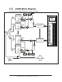
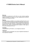
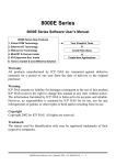
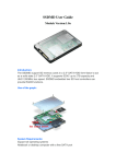
1.2. I-8048 Block Diagram
The signal flow block diagram is shown as follows:
Clr0
Falling
D-flipflop
Qf0
Qr0
D
Clk
Clr
Gi
High
AND
NOT
Rising
D-flipflop
D
Clk
Clr
Ef0
Er0
Isolated/TTL
In0, JP1
High
AND
OR
Rising
D-flipflop
Qr7
D
Clk
Clr
High
Isolated/TTL
In7, JP8
AND
Falling
D-flipflop
Qf7
D
Clk
Clr
NOT
High
AND
Clr7
Ef7
Er7
AND
ClrGi
Int e rrupt
CPU
I-8048 Hardware User’s Manual, Mar. 2005, Rev. 1.0
------
4
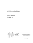
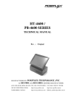
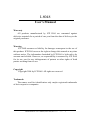
1.3. 8000 Interrupt Block Diagram
The 8000 series interrupt system block diagram is shown as follows:
80186
Slot0's Int
Slot1's Int
Slot2's Int
Slot3's Int
Slot4's int
IntClr4
INT0
INT1
INT2
INT3
NMI
D-filpflop
Clk
Q
Clr
Slot5's int D-filpflop
Q
Clk
IintClr5
Clr
Slot6's int
IntClr6
D-filpflop
Clk Q
Clr
Slot7's int
IntClr7
D-filpflop
Q
Clk
Clr
The CPU provides 4 interrupt inputs( INT0 ~ INT4 ) for slot0 ~ slot3
and non-masked interrupt input( NMI ) for slot4 ~ slot7. The NMI has
4slots totally 32 interrupt channels. To provide a function let 32 channels
share the NMI is hard. Thus, the library only supports 8048 plugged in
slot0 ~ slot3.
I-8048 Hardware User’s Manual, Mar. 2005, Rev. 1.0
------
5
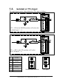
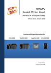
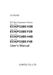
1.4.
Isolated or TTL Input
The input signal can be either isolated or TTL input as follows:
V cc
V in +
In 0
V in -
JP1
JP1 ~ JP8 in the DOWN position will select the
isolated input 1 ~ 8
V in V in +
V cc
In 0
JP1
JP1 ~ JP8 in the UP position will select
the TTL input 1 ~ 8
JP1
for ch0
JP2
for ch1
JP3
for ch2
JP4
for ch3
JP5
for ch4
JP6
for ch5
JP7
for ch6
JP8
for ch7
J
Isolated input (default)
I-8048 Hardware User’s Manual, Mar. 2005, Rev. 1.0
TTL input
------
6
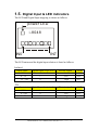
1.5. Digital Input & LED indicators
The LED and Digital Input mapping is shown as follows:
power LED
i -8048
IN0
IN7
The LED status and the digital input relation is listed as follows:
Isolated:
Input status
Digital Input( Logic level )
Electric signal
LED
OPEN
1
Low
OFF
0 ~ 1V
1
Low
OFF
3.5 ~ 30V
0
High
ON
TTL:
Input status Digital Input(Logic level)
Electric signal
LED
OPEN
1
Low
OFF
0 ~ 0.8V
0
Low
ON
2 ~ 5V
1
High
OFF
I-8048 Hardware User’s Manual, Mar. 2005, Rev. 1.0
------
7
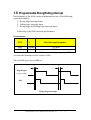
1.6. Programmable Rising/Falling interrupt
Each channel of the 8048 can be programmed as one of the following
types individually.
1. Rising edge interrupt input
2. Falling edge interrupt input
3. Rising edge and Falling edge interrupt input
Following is the 8048 interrupt performance
Performance:
CPU
T
Max interrupt frequency
40M
0.024ms
15.8KHz
80M
0.01ms
35KHz
T is the leading time between 8048 receives the input signal to CPU
executes the interrupt service routine ( ISR ).
The possible types are as follows:
T
T
Digital Input
(Logic value)
ISR
Rising Edge Interrupt
I-8048 Hardware User’s Manual, Mar. 2005, Rev. 1.0
------
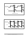
8
T
T
Digital Input
(Logic value)
ISR
Falling Edge Interrupt
T
T
T
T
Digital Input
(Logic value)
ISR
Rising and falling Edge Interrupt
I-8048 Hardware User’s Manual, Mar. 2005, Rev. 1.0
------
9
1.7. Clear Interrupt
Referring to Section 1.2, the interrupt signal will be latched until a clear
interrupt signal is activated. Refer to the appendix for the addresses of
clear interrupt signals.
The global interrupt, Gi, is shared by all eight signals. If any single
interrupt does not clear to LOW, then all interrupts will be blocked and the
CPU will not be able to receive any further interrupts. That is to say, the
programmer should ensure that the code clears the interrupt and make sure
that the global interrupt, Gi, is LOW in normal conditions.
Writing to BASE+0x0D will force the Gi to LOW for about 0.1uS. The Gi
will return to its previous state after writing. This mechanism will ensure
that the I-8048 works properly in a shared interrupt system. The only way
to clear the Gi is to clear all the Qfn and Qrn values listed in Section 1.2.
Reading from BASE+n will clear both Qfn and Qrn values.
Notes:
If any Qfn or Qrn value is Logic HIGH, the Gi will be HIGH to
block all further interrupts.
I-8048 Hardware User’s Manual, Mar. 2005, Rev. 1.0
------
10
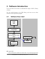
2. Software Introduction
Users can follow the sections to understand the usage of 8048’s Library
software.
We offer multi-functions in the 8048 library, and users can use these
functions to develop 8048’s program.
2.1.
Software flow chart
Initial
8048
Enable falling edge or
rising edge
Install
Interrupt service routine
(ISR)
User's
loop function
External signal
ISR
Initial 8048:
Gives all internal variables an initial value. Any interrupt signal clear
I-8048 Hardware User’s Manual, Mar. 2005, Rev. 1.0
------
11
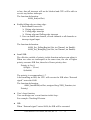
to low, then all interrupt will not be blocked and CPU will be able to
receive any further interrupts.
The function declaration :
i8048_Init(int Slot)
♦ Enable falling edge or rising edge:
1. Each channel can set to:
Rising edge interrupt
Falling edge interrupt
Rising edge and Falling edge interrupt
2. User can enable one channel, several channels or all channels as
interrupt signal input.
The function declaration:
i8048_Set_FallingReg(int Slot, int Channel, int Enable)
i8048_Set_RisingReg (int Slot, int Channel, int Enable)
♦ Install ISR:
We offer the variable of priority in this function and user can adjust it.
When two slots are interrupted at the same time, the slot of higher
priority executes ISR first, then slot of lower priority does.
Priority is 0 to 8.
0(High) ~ 7(Low)
8(disable)
The priority is recommend as 6~7.
After installing an ISR, the CPU will execute the ISR when “External
signal” enters the 8048.
The function declaration:
i8048_InstallISR(int Slot, unsigned long *ISR_Function, int
Priority)
♦ User’s loop function:
User can design one’s own function in this loop .
For example: Checking DI status.
♦ ISR:
When “External signal” enters 8048, the ISR will be executed.
I-8048 Hardware User’s Manual, Mar. 2005, Rev. 1.0
------
12
Users can design their own functions in the ISR.
The ISR function declaration:
void interrupt far ISR_Function(void)
For example:
Sets an alarm immediately or gets an A/D value, when 8048
gets an interrupt signal.
I-8048 Hardware User’s Manual, Mar. 2005, Rev. 1.0
------
13
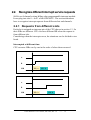
2.2. Recognize different interrupt service requests
8048 is an 8 channels rising/falling edge programmable interrupt module.
It can plug into slot 0 ~ slot 3 of the 8000 MCU. The section introduces
how to recognize interrupt requests from different slots and channels.
2.2.1 Requests from different slots
Each slot is assigned an interrupt pin of the CPU shown in section 1.3. So
their ISRs are different. CPU executes different ISR when the request is
from different slot.
Considering when the interrupts occur, the situations can be divided to two
kinds.
Interrupted at different time.
CPU executes ISRs one by one in the order of when them occurred.
A
B
ISR
ISR A
ISR B
A
B
ISR
ISR A
ISR B
I-8048 Hardware User’s Manual, Mar. 2005, Rev. 1.0
------
14
Interrupted at the same time.
This situation, CPU uses Interrupt Priority to distinguish order of
execution. The request with higher interrupt priority will be serviced first.
The priority number of 80188/80186 CPU is
Enabled:
Disabled:
0 (High) ~ 7(Low)
8
For example:
A’s priority is 2
B’s priority is 6
CPU gets two requests, A and B, at the same time. Because A’s priority is
higher than B, CPU services A’s request to execute ISR_A first. And
ISR_B will not be executed unless ISR_A is finished.
A
B
ISR
ISR A
ISR B
Following table is the interrupt priority defined by the MiniOS7.
Function
Priority
COM0/1
1
TIMER
1
Ethernet,COM2/3/4
5
When you assign an interrupt priority for the 8048, you need to consider
all interrupt services of the system. We suggest users to assign 8048’s
priority to 6 or 7.
Demo program: INT_Slot.c
I-8048 Hardware User’s Manual, Mar. 2005, Rev. 1.0
------
15
2.2.2 Requests from different channels
All 8 channels of the 8048 share the same ISR. That means the code for
each channel are in the same ISR but different part. The 8048 provides
two interrupt event registers. One is for rising edge interrupt and another
for falling edge interrupt. By reading the registers, the program would
know which channels triggered the ISR.
Function declaration:
int i8048_Read_RisingEvent(iSlot,iChannel);
int i8048_Read_FallingEvent(iSlot,iChannel);
If the return value is not zero, that means the ISR was triggered by the
channel.
Demo program: INT_Ch.c
I-8048 Hardware User’s Manual, Mar. 2005, Rev. 1.0
------
16
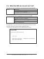
2.4. What the ISR can do and can’t do?
Normally, the functions that don’t use interrupt can be used in the ISR.
Can do
Mathematics
Accessing I/O ports
Accessing 8K series I/O modules
Accessing 7-segment LED of the SMMI
The functions that relative to interrupt can’t be used in the ISR.
Can’t do
Accessing COM ports
Accessing 87K series I/O modules
Timer
Accessing push buttons of the SMMI
Ethernet communication
But sometimes, we need to enable the interrupt option during execution
one ISR to allow CPU accept another interrupt request.
To do this, the ISR need to do some modification like below
Normal ISR
void interrupt far ISR_Function(void)
{
…..
//user’s code
…..
i8048_UnFreezeCPU(iSlot); //Telling CPU to end of interrupt
i8048_UnFreezeINT(iSlot);
}
I-8048 Hardware User’s Manual, Mar. 2005, Rev. 1.0
------
17
Normal ISR
void interrupt far ISR_Function(void)
{
//user’s code
…..
i8048_UnFreezeCPU(iSlot); //Telling CPU to end of interrupt
_asm sti //enable interrupt option
//user’s code
Can accept other interrupt
…..
i8048_UnFreezeINT(iSlot);
}
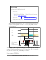
When the ISR is modified to be able to accept other interrupt service
request, the timing chart becomes as follows. (Only ISR_A enable
interrupt option.)
A
B
ISR
ISR A
ISR B
ISR A
Calling “_asm sti”
CUP ability to
accept
interrupt request
After calling “_asm sti” in the ISR_A, the CPU can accept other interrupt
request. When interrupt B occurs, the CPU jumps from ISR_A to execute
ISR_B. And continues ISR_A till ISR_B is finished.
Demo program: INT_INT.c
I-8048 Hardware User’s Manual, Mar. 2005, Rev. 1.0
------
18
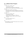
2.4. Software Demo Program
1.INT_Ch
• One I-8048 is installed in slot0.
• Multi-channels are enabled.
• Multi-channels active rising edge and falling edge.
• ”EOI” at the end of ISR(NO accept other interrupt to execution).
2.INT_Slot
• Two I-8048 are installed in slot0 and slot1.
• Single channel active rising edge or falling edge in slot0 and slot1.
• The INT_Slot’s ”EOI” at the end of ISR(NO accept other interrupt
to execution).
3.INT_INT
• One I-8048 is installed in slot0.
• Single channel are enabled.
• Single channel active rising edge or falling edge.
• “EOI” at the beginning of ISR(Accept other interrupt to
execution).
4.DI
• The I-8048 is installed in slot(0~7).
• Reads 8048 DI’s state.
Note:
Executing ISR can’t use call of DOS and printf, unless user puts the
EOI in the beginning of ISR.
I-8048 Hardware User’s Manual, Mar. 2005, Rev. 1.0
------
19
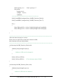
2.4.1 Int_Ch
/*******************************************************************
INT_Ch.c:
Multi-channels as rising or falling edge interrupt in single
slot.
Compiler:
BC++ 3.1,
Turbo C ++ 1.01(3.01) (free from
http://community.borland.com/museum)
MSC 6.0,
MSVC 1.52.
Compile mode: large
Project:
INT_Ch.c
..\Lib\(8000E.Lib,8000.Lib)
********************************************************************/
#include "..\..\lib\8000E.h"
#include "..\lib\8048.h"
void interrupt far ISR_Function(void);
int iSlot;
void main(void)
{
InitLib( );
Print("Please selection slot(0~3): ");
Scanf("%d\n\r",&iSlot);
i8048_Init(iSlot);
//Enable channel 0 as rising edge interrupt.
i8048_Set_RisingReg(iSlot,0,1); //0:channel 0
1:Enable
//Enable channel 0,1,2 as falling edge interrupt.
i8048_Set_FallingReg(iSlot,0,1); //0:channel 0
i8048_Set_FallingReg(iSlot,1,1); //0:channel 0
i8048_Set_FallingReg(iSlot,2,1); //0:channel 0
1:Enable
1:Enable
1:Enable
I-8048 Hardware User’s Manual, Mar. 2005, Rev. 1.0
------
20
//Install ISR
i8048_InstallISR(iSlot,(unsigned long *)&ISR_Function,6); //Priority : 6
for(;;)
{
Print("Rising S%dC0==%d Falling S%dC0==%d S%dC1==%d
S%dC2==%d\n\r",iSlot,i8048_RisingEventCount[iSlot][0]
,iSlot,i8048_FallingEventCount[iSlot][0]
,iSlot,i8048_FallingEventCount[iSlot][1]
,iSlot,i8048_FallingEventCount[iSlot][2]);
}
}
/********************************************************
Please don's use the Print or printCom1 function in ISR,
these function will cause the problem.
*********************************************************/
void interrupt far ISR_Function(void)
{
if(i8048_Read_RisingEvent(iSlot,0))
{
//Add user's ISR code for channel0.
}
if(i8048_Read_FallingEvent(iSlot,0))
{
//Add user's ISR code for channel0.
}
if(i8048_Read_FallingEvent(iSlot,1))
{
//Add user's ISR code for channel1.
}
if(i8048_Read_FallingEvent(iSlot,2))
{
//Add user's ISR code for channel2.
}
I-8048 Hardware User’s Manual, Mar. 2005, Rev. 1.0
------
21
i8048_UnFreezeCPU(iSlot);
i8048_UnFreezeINT(iSlot);
//Clear interrupt status of 8048.
}
I-8048 Hardware User’s Manual, Mar. 2005, Rev. 1.0
------
22
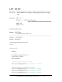
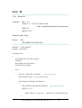
2.4.2 Int_Slot
/*******************************************************************
INT_Slot.c:
Compiler:
Single-channels as rising or falling edge interrupt in
multi-slots.
BC++ 3.1,
Turbo C ++ 1.01(3.01) (free from
http://community.borland.com/museum)
MSC 6.0,
MSVC 1.52.
Compile mode: large
Project:
INT_Slot.c
..\Lib\(8000E.Lib,8000.Lib)
****************************************************************/
#include "..\..\Lib\8000E.h"
#include "..\lib\8048.h"
void interrupt far ISR_Function_Slot0(void);
void interrupt far ISR_Function_Slot1(void);
void main(void)
{
InitLib( );
i8048_Init(0);
i8048_Init(1);
//Slot 0
//Enable channel 0,1 as rising edge interrupt.
i8048_Set_RisingReg(0,0,1); //slot 0 channel 0
1=Enable
//Slot = 1
//Enable channel 0,1 as rising edge interrupt.
i8048_Set_RisingReg(1,0,1); // slot 1 channel 0
1=Enable
/******************************************
I-8048 Hardware User’s Manual, Mar. 2005, Rev. 1.0
------
23
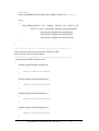
Slot0's priority is 6.
Slot1's priority is 7.
Set priority
Priority (0~8)
0(High) ~ 7(Low)
8(disable)
******************************************/
i8048_InstallISR(0,(unsigned long *)&ISR_Function_Slot0,6);
i8048_InstallISR(1,(unsigned long *)&ISR_Function_Slot1,7);
for(;;)
{
Print("Rising S0C0==%d \n\r",i8048_RisingEventCount[0][0]);
Print("Rising S1C0==%d \n\r",i8048_RisingEventCount[1][0]);
}
}
/*******************************************************************
Allow the other interrupt to execute.
Please don's use the Print or printCom1 function in ISR,
these function will cause the problem.
********************************************************************/
void interrupt far ISR_Function_Slot0(void)
{
if(i8048_Read_RisingEvent(0,0))
{
//Add user's ISR code for channel 0.
}
i8048_UnFreezeCPU(0);
i8048_UnFreezeINT(0);
//Clear interrupt status of 8048.
}
void interrupt far ISR_Function_Slot1(void)
{
if(i8048_Read_RisingEvent(1,0))
{
//Add user's ISR code for channel 0.
}
I-8048 Hardware User’s Manual, Mar. 2005, Rev. 1.0
------
24
i8048_UnFreezeCPU(1);
i8048_UnFreezeINT(1);
//Clear interrupt status of 8048.
}
I-8048 Hardware User’s Manual, Mar. 2005, Rev. 1.0
------
25
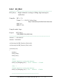
2.4.3 Int_Int
/*********************************************************************
INT_Int.c:
CPU accept external interrupt request during ISR.
Compiler: BC++ 3.1,
Turbo C ++ 1.01(3.01) (free from
http://community.borland.com/museum)
MSC 6.0,
MSVC 1.52.
Compile mode: large
Project:
INT_int.c
..\Lib\(8000E.Lib,8000.Lib)
*********************************************************************/
#include "..\..\Lib\8000E.h"
#include "..\lib\8048.h"
void interrupt far ISR_Function(void);
int iSlot;
void main(void)
{
InitLib( );
Print("Please selection slot(0~3): ");
Scanf("%d\n\r",&iSlot);
i8048_Init(iSlot);
//Enable channel 0 as rising edge interrupt.
i8048_Set_RisingReg(iSlot,0,1); //0:channel 0
1:Enable
//Install ISR
i8048_InstallISR(iSlot,(unsigned long *)&ISR_Function,6); //priority: 6
}
/********************************************************
I-8048 Hardware User’s Manual, Mar. 2005, Rev. 1.0
------
26
Please don's use the Print or printCom1 function in ISR,
these function will cause the problem.
*********************************************************/
void interrupt far ISR_Function(void)
{
i8048_UnFreezeCPU(iSlot);
_asm sti
//CPU accept other interrupt request.
if(i8048_Read_RisingEvent(iSlot,0))
{
Print(“INT\n\r”);
}
i8048_UnFreezeINT(iSlot); //Clear interrupt status of 8048.
}
I-8048 Hardware User’s Manual, Mar. 2005, Rev. 1.0
------
27
2.4.4 DI
/********************************************************************
DI.c : Reads DI.
Compiler:
BC++ 3.1,
Turbo C ++ 1.01(3.01) (free from
http://community.borland.com/museum)
MSC 6.0,
MSVC 1.52.
Compile mode: large
Project:
DI.c
..\Lib\(8000E.Lib,8000l.Lib)
*********************************************************************/
#include "..\..\Lib1\8000E.h"
#include "..\lib\8048.h"
void main(void)
{
int iChannel,iDI_ALL,iDI_Ch,iSlot;
InitLib( );
Print("Please selection Slot:");
Scanf("%d\n\r",&iSlot);
for(;;)
{
iDI_ALL=i8048_DI_ALL(iSlot);
//Read all channel.
Print("DI ALL status== %x \n\r",iDI_ALL);
for(iChannel=0;iChannel<8;iChannel++)
{
iDI_Ch=i8048_DI_Ch(iSlot,iChannel); //Read signle channel.
if(iDI_Ch == 0)
{
Print("CH%d ==>Logic %d
LED ON \n\r",iChannel,iDI_Ch);
}
I-8048 Hardware User’s Manual, Mar. 2005, Rev. 1.0
------
28
else
Print("CH%d ==>logic %d
LED OFF \n\r",iChannel,iDI_Ch);
}
}
}
I-8048 Hardware User’s Manual, Mar. 2005, Rev. 1.0
------
29
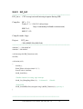
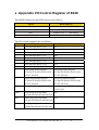
♦ Appendix I/O Control Register of 8048
The BASE address for the 8000 series is as follows:
SLOT
BASE(address)
Slot0
BASE=0x80 = SlotAddr[0]
Slot1
BASE=0xA0 = SlotAddr[1]
Slot2
BASE=0xC0 = SlotAddr[2]
BASE=0xE0 = SlotAddr[3]
Slot3
The I/O control registers are as follows:
Offset
Read (BASE+Offset) Address
Write (BASE+Offset) Address
0
Clear interrupt input 0, Clr0
N/A
1
Clear interrupt input 1, Clr1
N/A
2
Clear interrupt input 2, Clr2
N/A
3
Clear interrupt input 3, Clr3
N/A
4
Clear interrupt input 4, Clr4
N/A
5
Clear interrupt input 5, Clr5
N/A
6
Clear interrupt input 6, Clr6
N/A
7
Clear interrupt input 7, Clr7
N/A
8
Read Rising Enable Register
Er7/Er6/Er5/Er4/Er3/Er2/Er1/Er0
D7=Er7, D0=Er0
Set Rising Enable Register
Er7/Er6/Er5/Er4/Er3/Er2/Er1/Er0
D7=Er7, D0=Er0
9
Read Falling Enable Register
Ef7/Ef6/Ef5/Ef4/Ef3/Ef2/Ef1/Ef0
D7=Ef7, D0=Ef0
Set Falling Enable Register
Ef7/Ef6/Ef5/Ef4/Ef3/Ef2/Ef1/Ef0
D7=Ef7, D0=Ef0
0x0A
Read Global Interrupt Status, Gi
Force Interrupt to LOW state about
0.1uS, ClrGi
0x0B
Read Rising Interrupt Status
N/A
Qr7/Qr6/Qr5/Qr4/Qr3/Qr2/Qr1/Qr0
0x0C
Read Falling Interrupt Status
N/A
Qf7/Qf6/Qf5/Qf4/Qf3/Qf2/Qf1/Qf0
0x0D
Read Digital Input
Di7/Di6/Di5/Di4/Di3/Di2/Di1/Di0
N/A
I-8048 Hardware User’s Manual, Mar. 2005, Rev. 1.0
------
30