1
I-7188XB Series User’s Manual
Warranty
All products manufactured by ICP DAS are under warranty regarding
defective materials for a period of one year, beginning from the date of
delivery to the original purchaser.
Warning
ICP DAS assumes no liability for any damage resulting from the use of
this product. ICP DAS reserves the right to change this manual at any
time without notice. The information furnished by ICP DAS is believed to
be accurate and reliable. However, no responsibility is assumed by ICP
DAS for its use, not for any infringements of patents or other rights of
third parties resulting from its use.
Copyright
Copyright©2007 by ICP DAS Co., Ltd. All rights are reserved.
Trademark
The names used for identification only may be registered trademarks of
their respective companies.
I-7188XB Series User’s Manual(Ver.1.0, Apr/2007, 7MH-020-10 ) --- 1
Table of Contents
1.
Introduction .................................................................................................. 4
1.1 FEATURES.....................................................................................................................5
1.2 SPECIFICATIONS..........................................................................................................6
1.3 Software and Document information ..............................................................................7
1.4 Hardware Information .....................................................................................................9
1.4.1 Schematics and Dimensions of the I-7188XB(D) ....................................................9
1.4.2 Pin Assignment......................................................................................................10
1.4.3 Mounting the I-7188XB(D).....................................................................................12
1.4.4 Block Diagram .......................................................................................................13
1.4.5 Wiring Diagrams for Application ............................................................................14
1.4.6 DI/DO wire connection ..........................................................................................18
1.4.7 Mounting the I/O Expansion Bus ...........................................................................19
2.
Quick Start .................................................................................................. 20
2.1
2.2
2.3
2.4
3.
Software Installation .....................................................................................................20
Connect the Download Cable to the Host PC...............................................................21
Downloading Programs to the I-7188XB(D) .................................................................23
MiniOS7 Upgrade .........................................................................................................27
Writing Your First Program ....................................................................... 29
3.1 Libraries........................................................................................................................29
3.2 Compiler and Linker .....................................................................................................30
3.3 The Detailed Steps for Programming............................................................................31
3.3.1 Download Turbo C++ version 1.01 ........................................................................31
3.3.2 Install Turbo C++ version 1.01...............................................................................33
3.3.3 Set the environment variables of the system.........................................................36
3.3.4 Build and Execute the Program.............................................................................38
4.
Operating Principles.................................................................................. 47
4.1 System Mapping...........................................................................................................47
4.2 Debugging custom Programs using COM1 ..................................................................48
4.3 Using the Download Port as a COM Port .....................................................................50
4.4 Functions and Demo Programs List .............................................................................51
4.5 COM Port Comparison .................................................................................................54
4.6 Using the COM Ports....................................................................................................55
4.6.1 To print from the COM port ....................................................................................56
4.6.2 To Use COM1/COM2 for an RS-485 Application ...................................................57
4.6.3 To Send a Command to an I-7000 module ............................................................57
4.7 Using the Red LED and 7-SEG LED Display ...............................................................60
4.8 Accessing the I-7188XB(D) Memory ............................................................................61
4.8.1 Using Flash Memory .............................................................................................61
4.8.2 Using RTC and NVRAM ........................................................................................62
4.8.3 Using EEPROM.....................................................................................................63
4.9 Using the Watchdog Timer ...........................................................................................65
4.10 Using the Timer Function..............................................................................................67
4.11 Using Digital Input and Digital output............................................................................68
4.12 Using the I/O Expansion Bus........................................................................................70
4.12.1 Definition of an I/O Expansion Bus........................................................................70
4.12.2 I/O Expansion Boards............................................................................................73
5.
Applications ............................................................................................... 75
5.1 Embedded Controllers..................................................................................................75
I-7188XB Series User’s Manual(Ver.1.0, Apr/2007, 7MH-020-10 ) --- 2
5.2
5.3
5.4
5.5
5.6
5.7
Local Real Time Controller (RTC)................................................................................. 76
Remote Local Controller............................................................................................... 77
PLC I/O Expansion Application..................................................................................... 78
Radio Modem Application............................................................................................. 80
An Application Using 4 COM Ports (1).......................................................................... 82
An Application Using 4 COM Ports (2).......................................................................... 83
Appendix A: What is MiniOS7........................................................................... 84
Appendix B: MiniOS7 Utility and 7188XW ....................................................... 87
MiniOS7 Utility ..................................................................................................................... 87
7188XW............................................................................................................................... 89
Appendix C: Comparison Table........................................................................ 98
Appendix D: Library Function List................................................................... 99
Appendix E: Compiling and linking ............................................................... 136
Using the TC Compiler ...................................................................................................... 136
Using the BC++ Compiler .................................................................................................. 139
Using MSC Compiler ......................................................................................................... 145
Using MSVC++ Compiler................................................................................................... 147
Appendix F: Glossary...................................................................................... 152
I-7188XB Series User’s Manual(Ver.1.0, Apr/2007, 7MH-020-10 ) --- 3
1. Introduction
The I-7188XB(D) is a series of expandable embedded controllers
designed for industry applications and can be used to replace PC or
PLC devices in harsh environments. The I-7188XB(D) also has support
for an I/O expansion bus, which can be used to implement various I/O
functions, such as D/I, D/O, A/D, D/A, UART, Flash memory, battery
backup SRAM, AsicKey and other I/O functions. Most types of I/O
function can be implemented using this bus. ICP DAS offers more than
20 types of I/O Expansion Board for the I-7188XB(D), which can be
used to expand the features of the controller. Depending on the type of
embedded firmware programs that are being developed, and which I/O
Expansion Board, the I-7188XB(D) can be used as a single versatile
controller.
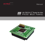
Package List
In addition to this manual, the shipping package includes the following
items:
One I-7188XB(D) module
One download cable (CA0910)
One companion CD containing software drivers and digital
versions of the user manuals
One copy of the release notes
CA0910
Note: If any of these items are missing or damaged, please contact
your local distributors for more information. We recommend that you
save the shipping materials and cartons in case you want to ship the
product in the future.
I-7188XB Series User’s Manual(Ver.1.0, Apr/2007, 7MH-020-10 ) --- 4
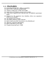
1.1 FEATURES
Embedded 80188 CPU, 40M or compatible
Built-in RTC, NVRAM and EEPROM
2 Built-in COM ports: COM1 and COM2
64-bit internal hardware-unique serial number
COM driver supports both interrupt and 1K QUEUE input/output
buffer
Support for I/O expansion bus interface (Only one expansion
board can be added)
One Digital Input Channel
One Open-collector output Channel
Built-in self-tuner ASIC controller on the RS-485 port
Optional 7-segment LED display
Built-in MiniOS7 by ICP DAS
Program download port: COM1
I-7188XB Series User’s Manual(Ver.1.0, Apr/2007, 7MH-020-10 ) --- 5
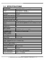
1.2 SPECIFICATIONS
CPU module
CPU
80188 CPU, 40MHz or compatible
256K bytes for I-7188XB
SRAM
512K bytes for I-7188XB/512
Flash
512K bytes
EEPROM
2K bytes
NVRAM
31 bytes
RTC (Real Time Clock) Yes
Hardware Serial Number Yes
Build-in Watchdog Timer Yes
Communication Interface
COM 1
COM 2
COM 3
COM 4
Ethernet Port
RS-232/RS-485 (Default is RS-232)
RS-485 (can be upgraded to 3000V isolated for OEM)
No
No
No
Digital Input
Input Channels
On Voltage Level
Off Voltage Level
1
+1V/DC Max. (Connect to GND)
+3.5V/DC to +30V/DC Max.
Digital Output
Output Channels
1
Output Type
Open-collector
Max Load Current
100mA
Load Voltage
+30V/DC Max.
LED Display
1 LED as Power/Communication Indicator
5-digit 7-segment LED (for I-7188XBD only)
Dimensions
123mm x 72mm x 33mm
Operating Environment
Operating temperature
Storage Temperature
Humidity
-25°C to +75°C
-40°C to +80°C
0 to 90%
Power
Power requirements
Power consumption
10 to 30V/DC (non-regulated)
2.0W for I-7188XB
3.0W for I-7188XBD
I-7188XB Series User’s Manual(Ver.1.0, Apr/2007, 7MH-020-10 ) --- 6
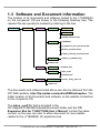
1.3 Software and Document information
The location of all documents and software related to the I-7188XB(D)
on the companion CD are shown in the following directory tree. The
relevant file can quickly be located by referring to the tree.
CD:\Napdos
7188XABC
7188XB
Demo
BC_TC
MSC
7188XB_DemoList.htm
Document
7188XB.pdf
IO_Expansion_bus_document.html
MiniOS7_document.html
Program_Develop_document.html
OS_image
7188xb_cr_20060614.img
Readme.html
Xboard
Demo
Document
Readme.html
iobus_e.pdf
X702X703.pdf
MiniOS7
Utility
MiniOS7_utility
minios7_utility_V311.exe
7188xw.exe
The documents and software listed above can also be obtained from the
ICP DAS website: http://ftp.icpdas.com/pub/cd/8000cd/napdos. The
folder location of all documents and software on the website is identical
to the companion CD.
The iobus_e.pdf file that is provided in the
CD:\Napdos\7188XABC\Xboard\Document\ folder and the “I/O
Expansion Bus for 7188X/7188E User’s Manual” contain the same
content, so the user can refer to either document for more details
related to the I-7188XB(D) I/O expansion bus.
I-7188XB Series User’s Manual(Ver.1.0, Apr/2007, 7MH-020-10 ) --- 7
Before continuing, it is recommended that you read the Readme.html,
which can be found in the CD:\Napdos\7188XABC\7188XB\. The latest
information available prior to shipping will be contained in this file.
I-7188XB Series User’s Manual(Ver.1.0, Apr/2007, 7MH-020-10 ) --- 8
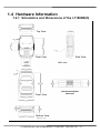
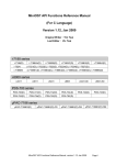
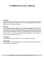
1.4 Hardware Information
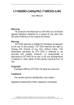
1.4.1 Schematics and Dimensions of the I-7188XB(D)
Top View
Rear View
Side View
Unit: mm
Front View
DIN-RAIL MOUNTING
BRACKET
Bottom View
I-7188XB Series User’s Manual(Ver.1.0, Apr/2007, 7MH-020-10 ) --- 9
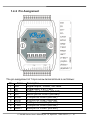
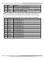
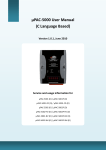
1.4.2 Pin Assignment
The pin assignment of 14-pin screw terminal block is as follows:
Pin
1
2
3
4
5
6
7
8
9
Name
DO
DI
D1+
D1CTS1
RTS1
GND
TXD1
RXD1
Description
Digital output, 100mA, 30V Max.
Digital input, 3.5V ~ 30V
DATA+ pin for COM1 (RS-485)
DATA- pin for COM1 (RS-485)
CTS pin for COM1 (RS-232)
RTS pin for COM1 (RS-232)
GND pin for COM1 (RS-232)
TXD pin for COM1 (RS-232)
RXD pin for COM1 (RS-232)
I-7188XB Series User’s Manual(Ver.1.0, Apr/2007, 7MH-020-10 ) --- 10
10
11
12
13
14
INIT*
D2+
D2+VS
GND
Initial pin
DATA+ pin for COM2 (RS-485)
DATA- pin for COM2 (RS-485)
V+ of power supply (+10 to +30V/DC, unregulated)
GND for the power supply
Note: The COM1 can be used as either an RS-232 or RS-485 port. It is
not recommended to use both RS-232 and RS-485 at the same time.
The pin assignment of top 14-pin screw terminal block is as follows:
Pin
Name Description
15 Pin 15
User defined pin 15
16 Pin 16
User defined pin 16
17 Pin 17
User defined pin 17
18 Pin 18
User defined pin 18
19 Pin 19
User defined pin 19
20 Pin 20
User defined pin 20
21 Pin 21
User defined pin 21
22 Pin 22
User defined pin 22
23 Pin 23
User defined pin 23
24 Pin 24
User defined pin 24
25 Pin 25
User defined pin 25
26 Pin 26
User defined pin 26
27 Pin 27
User defined pin 27
28 Pin 28
User defined pin 28
I-7188XB Series User’s Manual(Ver.1.0, Apr/2007, 7MH-020-10 ) --- 11
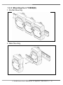
1.4.3 Mounting the I-7188XB(D)
1. Din-Rail Mounting
2. Stack Mounting
I-7188XB Series User’s Manual(Ver.1.0, Apr/2007, 7MH-020-10 ) --- 12
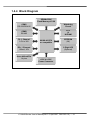
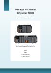
1.4.4 Block Diagram
SRAM=256K
Flash Memory=512K
COM1
RS-232/RS-485
Watchdog
Circuit
COM2
RS-485
RTC
&
NVRAM
DI: 1 Channel
3.5V to 30V
80188-40 CPU
or compatible
DO: 1 Channel
100mA, 30V
User defined Pin
14 pins
EEPROM
(2K)
5-Digit LED
(Optional)
+10V to +30V
Power Converter
I-7188XB Series User’s Manual(Ver.1.0, Apr/2007, 7MH-020-10 ) --- 13
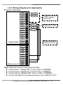
1.4.5 Wiring Diagrams for Application
Program download
7188XB/7188XBD
COM Port of the PC
GND
14
Ext.GND
+VS
13
Ext. 24V
D2-
12
D2+
11
Init*
10
RXD1
9
RXD
TXD1
8
TXD
GND
7
GND
RTS1
6
CTS1
5
D1-
4
D1+
3
DI
2
DO
1
RI
9
CTS
8
RTS
7
DSR
6
GND
5
DTR
4
TXD
3
RXD
2
DCD
1
Connect the INIT* pin
to GND to disable
autoexec.bat
Wiring label for CA0910
Program download
wiring connection
Note: There are 3 wires in the download cable:
Connect wire-1, labelled RX, to pin-9 of the I-7188XB(D)
Connect wire-2, labelled TX, to pin-8 of the I-7188XB(D)
Connect wire-3, labelled GND, to pin-7 of the I-7188XB(D)
Connect the DB-9 of the download cable to the COM Port of PC
I-7188XB Series User’s Manual(Ver.1.0, Apr/2007, 7MH-020-10 ) --- 14
Using a 3-wire RS-232 Port
7188XB/7188XBD
RXD
TXD
GND
COM1
RI
CTS
RTS
DSR
GND
DTR
TXD
RXD
RS-232 Device
DCD
Note: There are 3 wires as follows:
Connect the RXD to the TXD of the RS-232 device
Connect the TXD to the RXD of the RS-232 device
Connect the GND to the GND of the RS-232 device
I-7188XB Series User’s Manual(Ver.1.0, Apr/2007, 7MH-020-10 ) --- 15
Using a 5-wire RS-232 Port
7188XB/7188XBD
RXD
TXD
GND
RTS
CTS
COM1
RI
CTS
RTS
DSR
GND
DTR
TXD
RXD
RS-232 Device
DCD
Note: There are 5 wires as follows:
Connect the RXD to the TXD of the RS-232 device
Connect the TXD to the RXD of the RS-232 device
Connect the RTS to the CTS of the RS-232 device
Connect the CTS to the RTS of the RS-232 device
Connect the GND to the GND of the RS-232 device
I-7188XB Series User’s Manual(Ver.1.0, Apr/2007, 7MH-020-10 ) --- 16
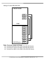
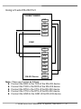
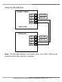
Using the RS-485 Port
7188XB/7188XBD
GND
14
Ext. GND
+VS
13
Ext. 24V
D2-
12
D2+
11
GND
10
Ext. GND
+VS
9
Ext. 24V
D2-
8
D2+
7
COM1/COM2
7000 Module
Note: The RS-485 interface can directly drive up to 256 I-7000 series
modules without the need for a repeater.
I-7188XB Series User’s Manual(Ver.1.0, Apr/2007, 7MH-020-10 ) --- 17
1.4.6 DI/DO wire connection
Digital Input Wire Connection
Input Type
ON State
DI value as 0
OFF State
DI value as 1
Relay Contact
TTL/CMOS Logic
Open Collector
Digital Output Wire Connection
Input Type
ON State
DO value as 1
OFF State
DO value as 0
Drive Relay
Resistance Load
I-7188XB Series User’s Manual(Ver.1.0, Apr/2007, 7MH-020-10 ) --- 18
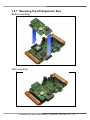
1.4.7 Mounting the I/O Expansion Bus
Before mounting:
After mounting:
I-7188XB Series User’s Manual(Ver.1.0, Apr/2007, 7MH-020-10 ) --- 19
2. Quick Start
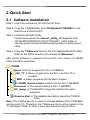
2.1 Software Installation
Step 1: Insert the companion CD into the CD drive.
Step 2: Copy the 7188XB folder from CD:\Napdos\7188XABC\ to the
Hard Drive of the Host PC.
Step 3: Install the MiniOS7 Utility.
Locate and execute the minios7_utility_v311.exe file from
CD:\NAPDOS\MINIOS7\UTILITY\MiniOS7_utility\ folder or
http://ftp.icpdas.com/pub/cd/8000cd/napdos/minios7/utility/minios7_
utility/
Step 4: Copy the 7188xw.exe file from the CD:\Napdos\MiniOS7\utility\
folder to the PATH directory, for example C:\Windows\.
After all the software is copied to the Host PC, the content of 7188XB
folder should be as follows:
7188XB
Demo
Demo programs for the I-7188XB(D)
BC_TC
Demo programs for the BC++ and the TC++
compiler
MSC
Demo programs for the MSC compiler
7188XB_DemoList.htm
Demo list for the I-7188XB(D)
Document
Documents related to the I-7188XB(D)
OS_image
The MiniOS7 image file matches the demo
programs
Readme.html
The detailed description about the 7188XB
folder
Note: The 7188xw.exe file is used as a bridge between the I-7188XB(D)
and the Host PC. Therefore, the 7188xw.exe file must be copied to the
“C:\Windows\” folder to allow it to be executed from any location.
I-7188XB Series User’s Manual(Ver.1.0, Apr/2007, 7MH-020-10 ) --- 20
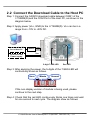
2.2 Connect the Download Cable to the Host PC
Step 1: Connect the CA0910 download cable between COM1 of the
I-7188XB(D) and the COM Port of the Host PC, as shown in the
diagram below.
Step 2: Apply power (Vs+, GND) to the I-7188XB(D). Vs+ can be in a
range from +10V to +30V DC.
Connect to the COM
Port of Host PC
GND
CA0910
TXD
RXD
Vs+
Connect to the
Power supply
GND
5-digit 7-SEG LED
Red LED
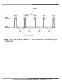
Step 3: After applying the power, the 5-digits of the 7-SEG LED will
continuously show as follows.
Hour
Minute
Second
If the non-display version of module is being used, please
continue to the next step.
Step 4: Check that the red LED continuously blinks one times and wait
for one second to next cycle. The diagram show as follows:
I-7188XB Series User’s Manual(Ver.1.0, Apr/2007, 7MH-020-10 ) --- 21
Note: Only the display version of the module will include a 5-digit
7-SEG LED.
I-7188XB Series User’s Manual(Ver.1.0, Apr/2007, 7MH-020-10 ) --- 22
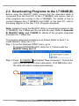
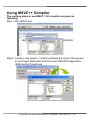
2.3 Downloading Programs to the I-7188XB(D)
Before using the MiniOS7 Utility, ensure that the download cable is
connected from the Host PC to the I-7188XB(D) and ensure that no
other programs are running on the I-7188XB(D). For details of how to
connect between the I-7188XB(D) and COM1 on the Host PC, refer to
the wiring diagram in the Sec.1.4.5---Program download.
Note: Instead of using the MiniOS7 Utility to download programs to the
I-7188XB(D), the 7188xw.exe file can also be used. Refer to Appendix
B: MiniOS7 Utility and 7188XW for details of the program download
procedure for 7188xw.exe.
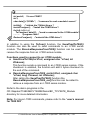
The program download procedure is as follows (Refer to Sec2.1 to
install MiniOS7 Utility Ver 3.11):
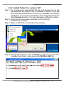
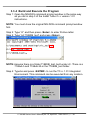
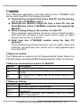
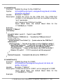
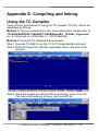
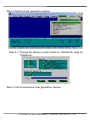
Step 1: From the Windows START menu, go to
Programs/ICPDAS/MiniOS7 Utility Ver 3.11/and locate the
MiniOS7 Utility Ver3.11.
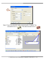
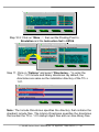
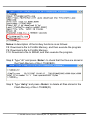
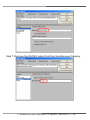
Step 2: Press
and Select “New connection”. Choose the
right COM port and set other parameters. Click OK button and
the utility will search module automatically.
1
I-7188XB Series User’s Manual(Ver.1.0, Apr/2007, 7MH-020-10 ) --- 23
2
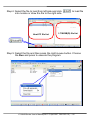
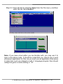
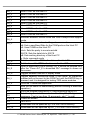
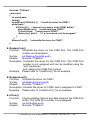
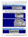
Step 3: See if the MiniOS7 Utility connects with I-7188XB. The
connected icon is
. The disconnected icon is
See here to know connection
status.
I-7188XB Series User’s Manual(Ver.1.0, Apr/2007, 7MH-020-10 ) --- 24
.
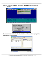
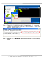
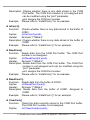
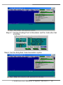
Step 4: Select the file to load from left side and click
into module or draw the file to the right side.
Host PC file list
to load file
I-7188XB(D) file list
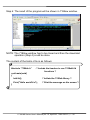
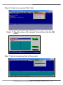
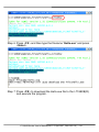
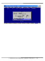
Step 5: Select the file and then press the right mouse button. Choose
the Run and press to execute the program.
I-7188XB Series User’s Manual(Ver.1.0, Apr/2007, 7MH-020-10 ) --- 25
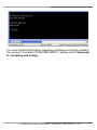
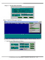
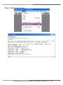
Step 6: The result of the program will be shown in 7188xw window.
NOTE: The 7188xw window has to be closed and then the download
operation (Step 4) could be done.
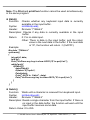
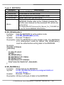
The content of the Hello.c file is as follows:
#include “7188xb.h”
/* Include the headers to use 7188xbl.lib
functions */
void main(void)
{
InitLib();
Print("Hello world!\r\n");
/* Initiate the 7188xb library */
/* Print the message on the screen */
}
I-7188XB Series User’s Manual(Ver.1.0, Apr/2007, 7MH-020-10 ) --- 26
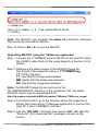
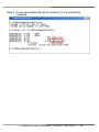
2.4 MiniOS7 Upgrade
ICP DAS will continue to add additional features to the MiniOS7 in the
future, so it is recommended that you periodically check the ICP DAS
website for the availability of updated versions of the MiniOS7.
Note: For a more detailed description of the MiniOS7, please refer to
Appendix A: What’s the MiniOS7.
The MiniOS7 Utility provides an easy way to upgrade MiniOS7. The
upgrade procedure is as follows:
Step 1: Get the latest version of MiniOS7 image file.
The format of the image file name is: TTYYMMDD.img
TT: TYPE of product.
YY: The year this image released
MM: The month this image released
DD: The day this image released
Note: The MiniOS7 image file contained on the companion CD can be
found in CD:\NAPDOS\MiniOS7\ directory. The latest version of
MiniOS7 can be downloaded from the ICP DAS website:
http://ftp.icpdas.com/pub/cd/8000cd/napdos/7188xabc/7188xb/os_image/
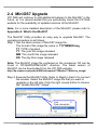
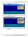
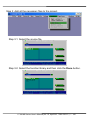
Step 2: Execute the MiniOS7 Utility. Refer to Step2 in Sec2.3 to connect
the module. Select the MiniOS7 image file that you want to
upgrade on the left side. Click the right mouse button to choose
the “Update MiniOS7 Image”.
I-7188XB Series User’s Manual(Ver.1.0, Apr/2007, 7MH-020-10 ) --- 27
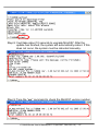
Step 3: It will take about 10 seconds for the upgrade to finish. If the
MiniOS7 was updated successfully, a Confirm action dialog box
will appear.
1
2
Step 4: Press
button and see the “Build” item to check the
version number of the MiniOS7. The diagram is as follow:
2
1
Note: Besides using the MiniOS7 Utility to upgrade the MiniOS7,
7188xw.exe can also be used. Refer to Appendix B: MiniOS7 Utility
and 7188XW for download procedures.
I-7188XB Series User’s Manual(Ver.1.0, Apr/2007, 7MH-020-10 ) --- 28
3. Writing Your First Program
3.1 Libraries
There are two function libraries for the I-7188XB(D) module as follows:
7188xbs.lib are programs for the small memory model.
7188xbl.lib are programs for the large memory model.
Both libraries are suitable for TC, BC++, MSC and MSVC++ compilers.
All declared functions are described in the header file, 7188xb.h.
The location of latest Library:
http://ftp.icpdas.com/pub/cd/8000cd/napdos/minios7/minios7_2.0/i-718
8xb/lib/ or CD: \Napdos\MiniOS7\MiniOS7_2.0\i-7188xb\lib
Hundreds of functions are supported in the 7188xbs.lib/7188xbl.lib files
as follows:
Function description
COM port
EEPROM
LED and 5-digit LED
Flash Memory
Timer and Watchdog
Timer
File
Connect to 7000 series
modules
Programmable I/O
Others
Example
InstallCOM0, InstallCOM1, InstallCOM2 ……
IsCOM0, IsCOM1, IsCOM2 ……
ToCOM0, ToCOM1, ToCOM2 ……
ReadCom0, ReadCom1, ReadCom2 ……
WriteEEP, ReadEEP, EnableEEP, ProtectEEP
LedOn, LedOff, Init5DigitLed, Show5DigitLedWithDot
FlashReadId, FlashErase, FlashRead,
FlashWrite ……
TimerOpen, TimeClose, TimerResetVlaue,
TimerReadValue, StopWatchReset,
StopWatchRead, StopWatchStop
GetFileNo, GetFileName, GetFilePositionByNo,
GetFilePositionByName
SendCmdTo7000, ReceiveResponseFrom7000
SetDio4Dir, SetDio4High, SetDio4Low, GetDio4
Kbhit, Getch, Putch, LineInput, Scanf ……
Note: For a more detailed description of the functions, please refer to
Appendix D: Library Function List.
I-7188XB Series User’s Manual(Ver.1.0, Apr/2007, 7MH-020-10 ) --- 29
3.2 Compiler and Linker
A C Language compiler must be used to develop any applications. Valid
compilers include:
BC++ 3.1~5.02
TC++ 1.01
TC 2.01
MSC
MSVC++ (Prior to version 1.52).
ICP DAS suggests that BC 3.1 is used as the compiler as the libraries
provided have been created using the BC 3.1 compiler. Special
attention should be paid to the following items before using the compiler
to develop custom applications:
Generate a standard DOS executable program.
Set the CPU to 80188/80186
Set the floating point to EMULATION if floating point computation
is required. (Make sure not to choose 8087)
Cancel the Debug Information function as this helps to reduce
program size. (MiniOS7 supports this feature.)
I-7188XB Series User’s Manual(Ver.1.0, Apr/2007, 7MH-020-10 ) --- 30
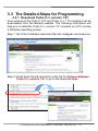
3.3 The Detailed Steps for Programming
3.3.1 Download Turbo C++ version 1.01
Free versions of the Turbo C 2.01 and Turbo C++ 1.01 compilers can be
downloaded from the Borland website. The following instructions will
help you to install the Turbo C++ version 1.01 compiler on a PC running
a Windows operating system.
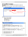
Step 1: Go to the CodeGear web site (http://dn.codegear.com/museum).
Step 2: Scroll down the bar and click on the link for Antique Software:
Turbo C++ version 1.01 to go to the download page.
I-7188XB Series User’s Manual(Ver.1.0, Apr/2007, 7MH-020-10 ) --- 31
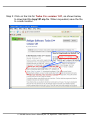
Step 3: Click on the link for Turbo C++ version 1.01, as shown below,
to download the tcpp101.zip file. When requested, save the file
to a safe location.
I-7188XB Series User’s Manual(Ver.1.0, Apr/2007, 7MH-020-10 ) --- 32
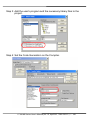
3.3.2 Install Turbo C++ version 1.01
Step 1: Go to where you downloaded the file, and double click on the
self-extracting file (tcpp101.zip) in Windows to extract it. This will
open a WinZip Self-Extractor window (you do NOT need WinZip
installed on your machine). By default, this will extract the files to
the C:\tctemp directory. You may designate a different location.
Step 2: Once the files have been extracted, exit the WinZip
Self-Extractor window.
Step 3: Open an MS-DOS command prompt window.
Step 4: Change the directory to the c:\tctemp (or wherever you put the
unzipped files folder), and execute the INSTALL.EXE file.
I-7188XB Series User’s Manual(Ver.1.0, Apr/2007, 7MH-020-10 ) --- 33
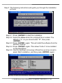
Step 5: The following instructions will guide you through the installation
process.
Step 5.1: Press <ENTER> to start the installation
Step 5.2: Select the drive where the unzipped file is located. The
default is “A”, so you should enter “C”, then press
<ENTER>.
Step 5.3: Press <ENTER> again. This will install the software from the
directory \tctemp.
Step 5.4: Press <ENTER> again. This allows Turbo C to be installed
on the Hard Drive.
Step 5.5: Use the Up/Down arrow keys (Press the up arrow once) to
select Start Installation, and then press <ENTER> again.
I-7188XB Series User’s Manual(Ver.1.0, Apr/2007, 7MH-020-10 ) --- 34
Step 5.6: At this point, the Turbo C++ version 1.01 compiler is
installed in C:\TC, which is where the tcc.exe executable is
also located.
I-7188XB Series User’s Manual(Ver.1.0, Apr/2007, 7MH-020-10 ) --- 35
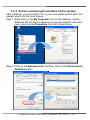
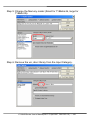
3.3.3 Set the environment variables of the system
After installing, you must add C:\TC to your executable search path. The
easiest way to do this is as follows:
Step 1: Right-click on the My Computer icon on the desktop. (Under
Windows XP, the My Computer icon may be located in the start
menu) and choose Properties from the context menu.
Step 2: Click on the Advanced tab, and then click on the Environment
Variables button.
I-7188XB Series User’s Manual(Ver.1.0, Apr/2007, 7MH-020-10 ) --- 36
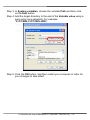
Step 3: In System variables, choose the variable Path and then click
on the Edit button.
Step 4: Add the target directory to the end of the Variable value using a
semi-colon as a separator. For example
”C:\TC\BIN;C:\TC\INCLUDE;”.
Step 5: Click the OK button, and then restart your computer in order for
your changes to take effect.
I-7188XB Series User’s Manual(Ver.1.0, Apr/2007, 7MH-020-10 ) --- 37
3.3.4 Build and Execute the Program
Step 1: Open the MS-DOS command prompt window in the same way
as you did in step 3 of the Install Turbo C++ version 1.01
instructions.
NOTE: You must close the original MS-DOS command prompt window
first.
Step 2: Type “d:” and then press <Enter> to enter D drive letter.
Step 3: Type “cd 7188XB_test” and press <Enter>.
NOTE: Assume there is a folder,7188XB_test, built under d:\. There is a
7188xb.h and 7188xbl.lib in the 7188XB_test folder.
Step 4: Type tc and press <ENTER> to run the TC++ 1.01 Integrated
Environment. This command can be executed from any location.
I-7188XB Series User’s Manual(Ver.1.0, Apr/2007, 7MH-020-10 ) --- 38
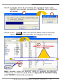
Step 5: Create a source file (*.c).
Step 5.1: Select New from the File menu.
Step 5.2: Type in following code. Note that the code is case-sensitive.
#include “7188xb.h”
void main(void)
{
InitLib();
Print("Hello world!\r\n");
}
I-7188XB Series User’s Manual(Ver.1.0, Apr/2007, 7MH-020-10 ) --- 39
Step 5.3: Save the file by selecting Save from the File menu, and then
enter the file name Hello.C.
Note: If you have a text editor you are familiar with, you may use it to
type in the above code. It should be noted that you cannot use a word
processor application for this, as you must use an application that saves
in plain text, such as notepad or edit. C language program files should
always be given a name ending in “.C”.
I-7188XB Series User’s Manual(Ver.1.0, Apr/2007, 7MH-020-10 ) --- 40
Step 6: Create a new project file (*.prj).
Step 6.1: Type the name of the project file and then click the OK
button.
Step 7: Add all necessary files to the project.
I-7188XB Series User’s Manual(Ver.1.0, Apr/2007, 7MH-020-10 ) --- 41
Step 7.1: Select the source file. Type “*.c” and press Enter in A area.
If the file you want is in B area, moving the green block to
choose the file and click the Add button. If not, moving the
green block to C area and press Enter to search the file.
A area
B area
C area
Step 7.2: Select the function library. Type “*.lib” and press Enter in A
area. If the file you want is in B area, moving the green block
to choose the file and click the Add button. If not, moving
the green block to C area and press Enter to search the file.
A area
B area
C area
Step 8: Click Done to exit.
I-7188XB Series User’s Manual(Ver.1.0, Apr/2007, 7MH-020-10 ) --- 42
Step 9: Click on “Options” and select full menus.
Step 10: Click on “Options” and select the compile menu item, then set
the Code generation options.
Step 10.1: Change the Memory model (Small for 7188xbs.lib, large
for 7188xbl.lib).
I-7188XB Series User’s Manual(Ver.1.0, Apr/2007, 7MH-020-10 ) --- 43
Step 10.2: Click on “More…”, then set the Floating Point to
Emulation and the Instruction Set to 80186.
Step 11: Click on “Options” and select “Directories…” to enter the
TC++ 1.01 include and library directories. By default, the
directories are same as the installation directory of the TC++
1.01.
Note: The Include Directories specifies the directory that contains the
standard include files. The Library Directories specifies the directories
that contain the TC++ 1.01 startup object files and run-time library files.
I-7188XB Series User’s Manual(Ver.1.0, Apr/2007, 7MH-020-10 ) --- 44
Step 12: Click on “Compile” and select “Make EXE file” to make the
project.
For instructions related to the downloading and execution of programs,
please refer to Section 2.3.
I-7188XB Series User’s Manual(Ver.1.0, Apr/2007, 7MH-020-10 ) --- 45
For more detailed information regarding compiling and linking related to
the various C compilers (TC/BC/MSC/MSVC), please refer to Appendix
E: Compiling and linking.
I-7188XB Series User’s Manual(Ver.1.0, Apr/2007, 7MH-020-10 ) --- 46
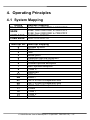
4. Operating Principles
4.1 System Mapping
Device
Flash ROM
SRAM
COM1 BASE
COM2 BASE
Interrupt No.
0
1
2
3
4
5
6
7
8
9
0A
0B
0C
0D
10
11
12
13
14
Address mapping
512K: from 8000:0000 to F000:FFFF
256K: from 0000:0000 to 3000:FFFF
512K: from 0000:0000 to 7000:FFFF
0XFF80 to 0XFF88
0XFF10 to 0XFF18
Interrupt mapping
Divided by zero
Trace
NMI
Break point
Detected overflow exception
Array bounds exception
Unused opcode exception
ESC opcode exception
Timer 0
Reserved
DMA-0
DMA-1
\INT0 of the I/O expansion bus
\INT1 of the I/O expansion bus
\INT4 of the I/O expansion bus
COM2
Timer 1
Timer 2
COM1
I-7188XB Series User’s Manual(Ver.1.0, Apr/2007, 7MH-020-10 ) --- 47
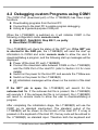
4.2 Debugging custom Programs using COM1
The COM1 Port (download port) of the I-7188XB(D) has three major
functions.
Downloading programs from the Host PC
Connecting to the Host PC to enable program debugging
Acting as a general-purpose COM port
When the I-7188XB(D) is switched on, it will initialize COM1 in the
following configuration under console mode:
Start Bit=1, Data Bit=8, Stop Bit=1, no parity
Baud Rate=115200 bps
The I-7188XB(D) will check the status of the INIT* pin. If the INIT* pin
is shorted to the GND pin, the I-7188XB(D) will send the start up
information to COM4 and enter console mode to allow the user to
download/debug a program, and the following start up messages will be
displayed.
Power off the Host PC and I-7188XB(D)
Connect the download cable between COM4 on the I-7188XB(D)
and the COM Port of the Host PC (refer to Section 2.2 for more
details)
Switch on the power for the Host PC and execute the 7188xw.exe
Switch on the power for the I-7188XB(D)
All initialization messages will be shown on the monitor of the Host
PC
If the INIT* pin is open, the I-7188XB(D) will search for the
autoexec.bat file. If the autoexec.bat file is present, the I-7188XB(D)
will execute it. If the autoexec.bat file is not present, the I-7188XB(D)
will revert to console mode to allow the user to download/debug a
program.
After completing the initialization stage, the I-7188XB(D) will use the
COM1 as its standard input/output. The standard output of the
I-7188XB(D) will be shown on the monitor of the Host PC. If a key is
pressed on the keyboard of the Host PC, the key code will be echoed to
the I-7188XB(D) as standard input. Therefore both the keyboard and
I-7188XB Series User’s Manual(Ver.1.0, Apr/2007, 7MH-020-10 ) --- 48
monitor of the Host PC can be used as standard input and output for the
I-7188XB(D) as follows:
Use 7188xw.exe or MiniOS7 Utility as a bridge between the
I-7188XB(D) and the Host PC
Execute 7188xw.exe or the MiniOS7 Utility on the Host PC to
setup this bridge
The keyboard of the Host PC
standard input of I-7188XB(D)
The monitor of the Host PC
standard output of I-7188XB(D)
In this way, the I-7188XB(D) can read data from the keyboard and
display it on the monitor. Thus, debugging a program will be easies and
effective.
Note: 7188xw.exe and the MiniOS7 Utility are provided on the
companion CD. Please refer to Section 2.2 for detailed wiring
information and Section 2.3 for details of how to download programs.
I-7188XB Series User’s Manual(Ver.1.0, Apr/2007, 7MH-020-10 ) --- 49
4.3 Using the Download Port as a COM Port
The download port (COM1) of the I-7188XB(D) can be used as a
general purpose RS-232 port in the following manner:
Step 1: Download custom programs and autoexec.bat to I-7188XB(D)
first.
Step 2: Switch off the I-7188XB(D) and remove the download cable from
the Host PC.
Step 3: Disconnect the INT* pin from the GND pin of the I-7188XB(D) if
they are connected.
Step 4: Switch on the I-7188XB(D) (no standard input, no standard
output, no debug information).
Step 5: Connect a download cable between a new RS-232 device and
the COM1 of the I-7188XB(D).
Step 6: Initialize the COM1 to the new configuration.
Step 7: The COM1 of the I-7188XB(D) can now be used a general
purpose RS-232 port.
I-7188XB Series User’s Manual(Ver.1.0, Apr/2007, 7MH-020-10 ) --- 50
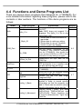
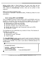
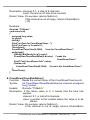
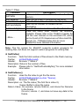
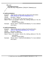
4.4 Functions and Demo Programs List
There are several demo programs that designed for I-7188XB(D). For
more detailed information regarding these programs, please refer to the
contents in later sections. The functions of the demo programs are as
follows:
Folder
Hello
Demo program
Hello_C
Hello_C++
C_Style_IO
Receive
COM_Port
Slv_COM
ToCom_In_Out
DateTime
IO_PIN
Led
LED
Seg7led
Config_1_Basic
File
Config_2_Advanced
Explanation
Section
Detecting if the operation system is 3.3.4
MiniOS7.
Note: MSC does not support C++
language. The Hello_C++ file is only
supported by BC.
1. Shows how to write a function to
input data.
2. Shows how to retrieve a string.
3. Shows how to use a C function:
sscanf, or just use Scanf().
Receive data from the COM Port.
4.6
The PC sends commands to the
I-7188XB(D), and receives responses
from the I-7188XB(D). Also shows how
to use another COM Port or LED to show
information to help debug a program.
Reads/writes the byte data via the
COM Port.
Reads the date and time from an
RTC and prints it on a monitor (user
can also set the date and time).
Reads/writes the DO and DI of the
I-7188XB(D).
Shows how to use the DelayMs function
to switch the LED ON or OFF.
Controls the red LED and 5-digit
7-segment LED.
In many applications, a text file is
needed in order to record specific
information so that the program can
read it. FSeek can be used to retrieve
specific information from a text file.
Extends config_1_Basic, and adds
GetProFileInt, GetProFileFloat and
GetProFileStr. These functions can
be used to determine the "Type" from
a text file.
I-7188XB Series User’s Manual(Ver.1.0, Apr/2007, 7MH-020-10 ) --- 51
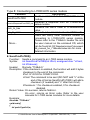
4.11
4.7
Demo5
EEPROM
EEPROM-r
EEPROM-w
Flash
Memory
Flash-r
Flash-w
NVRAM-r
NVRAM-w
Top-Mem
Reset
Runprog
Misc
SerialNumber
Watchdog
Shows how to access the NVRAM.
Writes a value to the EEPROM and
shows it on the monitor.
Reads the data that has been written
to the EEPROM.
Inputs a value and stores it in an
EEPROM block 1 peer address
(value will automatically increase by
1).
Reads, writes and erases the Flash
memory.
Reads the value that has been written
to the Flash memory.
Inputs a value written in the Flash
memory (value will automatically
increase by 1).
Reads the value that has been written
to NVRAM.
Writes a value to the NVRAM (value
will automatically increase by 1).
Demonstration of the
AllocateTopMemory function
Restores the initial values.
Uses the Ungetch function to run
another program.
Retrieves the serial number of the
I-7188XB(D).
Enables the Watchdog or bypasses
the enabled Watchdog.
7K87K_demo_for_com
7K87K_AI_for_Com
7K87K_DI_for_Com
Show how to connect and control the
7K87K_Module 7K87K_DIO_for_Com
7k or 87k series modules via COM2.
7k87K_DO_for_Com
AO_024_for_Com
AO_22_26_for_Com
A demonstration program showing
Timer
Demo90
how to use the Timer function.
Demo91
Show how to use the CountDownTimer
function on channel 0 to switch the LED
ON or OFF.
Demo92
Shows how to use the StopWatch
function on channel 0 to switch the
LED ON or OFF.
I-7188XB Series User’s Manual(Ver.1.0, Apr/2007, 7MH-020-10 ) --- 52
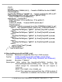
4.8
4.9
4.6.3
4.10
Demo96
Demo97
Demo98
XBoard
Shows how to use the InstallUserTimer
function to control the 5-digit 7-segment
LED.
Shows how to use the DelayMs function
to switch the LED ON or OFF.
Shows how to use the I-7188XB(D)
timer function to send/receive data to
or from 7000 series modules.
These are demo programs for all I/O
expansion boards that are applicable
to the I-7188XB(D).
I-7188XB Series User’s Manual(Ver.1.0, Apr/2007, 7MH-020-10 ) --- 53
4.12
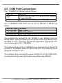
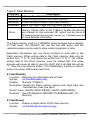
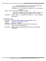
4.5 COM Port Comparison
The I-7188XB(D) COM ports are as follows:
COM Port
COM1
COM2
Hardware
80188’s on-chip UART-0, 5-wire RS-232 (Default)
or 2-wire RS-485
80188’s on-chip UART-1, 2-wire RS-485
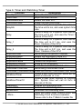
The I-7188XB(D) COM Ports can be set as RS-232 or RS-485 as
below:
COM Port Type
2-wire RS-485
3-wire RS-232
5-wire RS-232
Pin name
Data+, DataTXD, RXD, GND
TXD, RXD, GND, RTS, CTS
The programming required for the 16C550 is very different from the
80188 UART. Interrupt handling on the 80188 is also very different from
the 8259 on a PC. Therefore, the RS-232 application programs for PC
are not executed in the I-7188XB(D).
The software driver for the I-7188XB(D) is an interrupt driven library that
provides a 1K QUEUE buffer for each COM Port. The software is well
designed and easy to use.
The software driver provides the same interface for all two COM Ports,
so each port can be used in the same way without any difficulty.
I-7188XB Series User’s Manual(Ver.1.0, Apr/2007, 7MH-020-10 ) --- 54
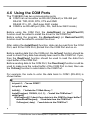
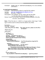
4.6 Using the COM Ports
The 7188XB(D) has two communication ports.
COM1 can act as either an RS-232 (Default) or RS-485 port
RS-232: TXD, RXD, RTS, CTS and GND
RS-485: D1+, D1- (Self-tuner ASIC inside)
COM2 is an RS-485 port (D2+, D2-, Self-tuner ASIC inside)
Before using the COM Port, the InstallCom() (or InstallCom1/2)
function must be called to install the driver for the COM Port.
Before exiting the program, the RestoreCom() (or RestoreCom1/2)
function must be called to uninstall the driver.
After calling the InstallCom() function, data can be read from the COM
Port, sent to the COM Port, printed from the COM Port and so on.
Before reading data from the COM port, the IsCom() function should be
used to check if any data has already been sent to the COM Port. If yes,
then the ReadCom() function should be used to read the data from
input buffer of the COM Port.
Before sending data to the COM Port, the ClearCom() function could be
used to make sure the output buffer of the COM Port is clear, then use
the ToCom() function to send data to the COM Port.
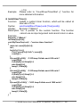
For example, the code to echo the data back to COM1 (RS-232) is
shown below.
int port=1; /*to use COM1*/
int quit=0, data;
InitLib(); /* Initiate the 7188xb library */
InstallCom(port, 115200L, 8, 0, 1); /*install the COM driver*/
while(!quit){
if(IsCom(port)){ /*check if any data is in the COM Port input buffer*/
data=ReadCom(port); /*read data from the COM Port*/
ToCom(port, data); /*send data via the COM Port*/
I-7188XB Series User’s Manual(Ver.1.0, Apr/2007, 7MH-020-10 ) --- 55
if(data==’q’) quit=1;
/*if ‘q’ is received, exit the program*/
}
}
RestoreCom(port);
/*uninstall the COM driver*/
Use the “port” variable to switch from COM1 to COM2, simply change
port=1 to port=2.
If the program is set to use COM1, the code can be altered as follows:
int quit=0, data;
InitLib(); /* Initiate the 7188xb library */
InstallCom1(115200L, 8, 0, 1); /*install the COM1 driver*/
while(!quit){
if(IsCom1()){ /*check if any data is in the COM1 input buffer*/
data=ReadCom1(); /*read data from COM1*/
ToCom1(data); /*send data via COM1*/
if(data==’q’) quit=1; /*if ‘q’ is received, exit the program*/
}
}
RestoreCom1(); /*uninstall the COM driver*/
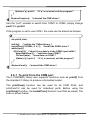
4.6.1 To print from the COM port
The I-7188XB(D) library also supports functions such as printf() from
the standard C library to produce a formatted output.
The printCom() function can be used for all COM Ports, and
printCom1/2 can be sued for individual ports. Before using the
printCom() function, the InstallCom() function must first be called. The
code is shown below:
I-7188XB Series User’s Manual(Ver.1.0, Apr/2007, 7MH-020-10 ) --- 56
int port=2;
int i;
/*to use COM2*/
InitLib(); /* Initiate the 7188xb library */
InstallCom(port, 115200L, 8, 0, 1); /*install the COM2 driver*/
for(i=0; i<10; i++){
printCom(port, “Test %d\r\n”, i); /*print data from COM2*/
}
RestoreCom(port); /*uninstall the COM driver*/
4.6.2 To Use COM1/COM2 for an RS-485 Application
COM1/COM2 is a 2-wire RS-485 COM Port, and includes the following
2 pins:
D+: connect to the Data+ of the RS-485 network
D-: connect to the Data- of the RS-485 network
COM1/COM2 is a half-duplex 2-wire RS-485 network and cannot be
used in a full-duplex 4-wire application. It is designed to directly drive
I-7000 series modules.
Send/receive directional control in a 2-wire RS-485 network is very
important. Therefore, the I-7188XB(D) is equipped with a Self-Tuner
ASIC controller for all RS-485 ports, which will automatically detect and
control the send/receive direction of the RS-485 network. In this manner,
the application programmer does not have to worry about the
send/receive direction control for the RS-485 network.
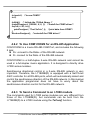
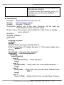
4.6.3 To Send a Command to an I-7000 module
The commands used for I-7000 series modules are very different from
those of the I-7188XB(D), but commands can be sent from the
I-7188XB(D) to a I-7000 module using the ToCom() function.
I-7188XB Series User’s Manual(Ver.1.0, Apr/2007, 7MH-020-10 ) --- 57
Using COM1/COM2 to connect and control I-7000 modules
The procedure for I-7000-related applications is as follows:
Step 1: The I-7188XB(D) sends a command string to the I-7000 series
modules.
Step 2: The destination I-7000 modules execute the command.
Step 3: The destination I-7000 modules delay by 1 byte to allow for
setting time.
Step 4: The destination I-7000 modules echo the result string back to
the I-7188XB(D).
Note: The delay time used in step 3 is only 1 byte.
I-7188XB(D)
Connect to the
Power supply
+Vs
DATA+
DATA-
GND
RS-485
(Data+, Data-)
DATA+
Connect to the
Power supply
+Vs
DATA-
GND
I-7188XB(D)/I-7000
The example code for sending a command to COM2 (RS-485) is shown
below.
I-7188XB Series User’s Manual(Ver.1.0, Apr/2007, 7MH-020-10 ) --- 58
int port=2; /*to use COM2*/
int i;
char data[ ]=”$01M\r”; /*command to read a module’s name*/
InitLib(); /* Initiate the 7188xb library */
InstallCom(port); /*install the COM2 driver*/
for(i=0; i<5; i++)
ToCom(port, data[i]); /*send a command to the I-7000 module*/
……… /*program code*/
RestoreCom(port); /*uninstall the COM driver*/
In addition to using the ToCom() function, the SendCmdTo7000()
function can also be used to send commands to an I-7000 series
module. The ReceiveResponseFrom7000() function can be used to
receive the response from an I-7000 series module.
Functions used to connect to an I-7000 module:
SendCmdTo7000(int iPort, unsigned char *cCmd, int
iChksum);
This function sends a command to an I-7000 series module. If the
checksum is enabled, the function will add 2 bytes checksum to
the end of the command.
ReceiveResponseFrom7000_ms(int iPort, unsigned char
*cCmd, long lTimeout, int iChksum);
After calling the SendCmdTo7000() function the
ReceiveResponseFrom7000_ms() function can be called to
retrieve a response from an I-7000 series module.
Refer to the demo programs in the
CD:\Napdos\7188XABC\7188XB\Demo\BC_TC\7K87K_Module
directory for more detailed information.
Note: For more I-7000 commands, please refer to the “user’s manual
for 7000 DIO”.
I-7188XB Series User’s Manual(Ver.1.0, Apr/2007, 7MH-020-10 ) --- 59
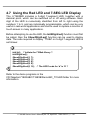
4.7 Using the Red LED and 7-SEG LED Display
The I-7188XBD includes a 5-digit 7-segment LED, together with a
decimal point, which can be switched on or off using software. Each
digit of the LED is numerically identified from left to right using the
numbers 1 to 5, and are individually programmable, which can be very
useful in real world applications and can be used to replace a monitor or
touch screen in many applications.
Before attempting to use the LED, the Init5DigitLed() function must first
be called, then the Show5DigitLed() function can be used to display
data. The code required to display “7188d” on 5-digit 7-segment LED is
as follows:
InitLib(); /* Initiate the 7188xb library */
Init5DigitLed();
Show5DigitLed(1, 7);
Show5DigitLed(2, 1);
Show5DigitLed(3, 8);
Show5DigitLed(4, 8);
Show5DigitLed(5, 13); /* The ASCII code for ‘d’ is 13 */
Refer to the demo programs in the
CD:\Napdos\7188XABC\7188XB\Demo\BC_TC\LED folder for more
information.
I-7188XB Series User’s Manual(Ver.1.0, Apr/2007, 7MH-020-10 ) --- 60
4.8 Accessing the I-7188XB(D) Memory
4.8.1 Using Flash Memory
The I-7188XB(D) module contains 512K bytes of Flash memory which
includes space reserved for the MiniOS7. The MiniOS7 occupies the
0xF000 segment. So user can use the other segments whose total size
is 448K bytes.
Each bit of the Flash memory can only be written from 1 to 0 and cannot
be written from 0 to 1. The only way to change the data from 0 to 1 is to
call the EraseFlash() function to erase a block from the Flash Memory
(64K bytes). The user should decide whether to write to the block or to
erase it.
To write an integer to segment 0xD000, offset 0x1234 of the Flash
Memory, the code is as follows:
int data=0xAA55, data2;
char *dataptr;
int *dataptr2;
InitLib(); /* Initiate the 7188xb library */
dataptr=(char *)&data;
FlashWrite(0xd000, 0x1234, *dataptr++);
FlashWrite(0xd000, 0x1235, *dataptr);
/* read data from the Flash Memory method 1 */
dataptr=(char *)&data2;
*dataptr=FlashRead(0xd000, 0x1234);
*(dataptr+1)=FlashRead(0xd000, 0x1235);
/* read data from the Flash memory method 2 */
dataptr2=(int far *)_MK_FP(0xd000, 0x1234);
data=*data
Reading data from the Flash Memory is somewhat like reading data
from SRAM. The user should allocate a far pointer to point to the
memory location first, and then use this pointer to access the memory.
I-7188XB Series User’s Manual(Ver.1.0, Apr/2007, 7MH-020-10 ) --- 61
Before writing data to Flash Memory, the user must first call the
FlashWrite() function, and check whether data can be written or not.
After calling the EraseFlash() function, data can be written to that
segment.
Refer to the demo programs in the
CD:\Napdos\7188XABC\7188XB\Demo\BC_TC\Memory folder for more
information.
4.8.2 Using RTC and NVRAM
The I-7188XB(D) module contains both an RTC and NVRAM, which are
located on the same chip, and an onboard Li battery that is used as
backup for at least 10 years. The features of the RTC are as follows:
BIOS support for RTC time and data
MiniOS7 supports RTC time and date
Seconds, minutes, hours, date of the month
Month, day of the week, year (Leap year valid up to 2079)
NVSRAM: 31 bytes
The NVRAM can be read/written any number of times. The features of
NVRAM are as follows:
Data Validity: 10 years
Read/write cycles: unlimited
Total 31 bytes
The ReadNVRAM() function can be used to read one byte of data from
the NVRAM and WriteNVRAM() function can be used to write one byte
of data to the NVRAM. The code to write data to NVRAM address 0 is
shown below.
int data=0x55, data2;
InitLib(); /* Initiate the 7188xb library */
WriteNVRAM(0, data);
data2= ReadNVRAM(0);
/* now data2=data=0x55 */
I-7188XB Series User’s Manual(Ver.1.0, Apr/2007, 7MH-020-10 ) --- 62
To write an integer (two bytes) to the NVRAM, use the code shown
below.
int data=0xAA55, data2;
char *daraptr=(char *)&data;
InitLib(); /* Initiate the 7188xb library */
WriteNVRAM(0, *dataptr);
/* write the low byte */
WriteNVRAM(1, *dataptr+1);
/* write the high byte */
dadaptr=(char *)&data2;
*dataptr=ReadNVRAM(0);
/* read the low byte */
(*dataptr+1)=ReadNVRAM(1);
/* read the high byte */
/* now data2=data=0xAA55 */
Refer to the demo programs in the
CD:\Napdos\7188XABC\7188XB\Demo\BC_TC\Memory folder for more
information.
4.8.3 Using EEPROM
The EEPROM is designed to store data that is not changed frequently,
such as:
Module ID, configuration settings
COM port configuration settings
Small databases
The erase/write cycle of the EEPROM is limited to1,000,000 erase/write
cycles, so it should not be changed frequently when testing. The
EEPROM can be erased/written in a single byte, so it is very useful in
real world applications.
The I-7188XB(D) has 2K bytes of EEPROM memory, containing 8
blocks and each block contains 256 bytes, giving a total of 2048 bytes of
EEPROM memory. Normally, the EEPROM is in protected mode by
default, meaning that no data can be written to the EEPROM. The
EE_WriteEnable() function must be called to unprotect it before writing
I-7188XB Series User’s Manual(Ver.1.0, Apr/2007, 7MH-020-10 ) --- 63
any data.
For example: To write data to EEPROM block1, address 10, first call the
EE_WriteEnable() function . The code is shown below.
int data=0x55, data2;
InitLib(); /* Initiate the 7188xb library */
EE_WriteEnable();
EE_MultiWrite(1, 10, 1, &data);
EE_WriteProtect();
EE MultiRead(1, 10, 1, &data2);
/* now data2=data=0x55 */
Note: To write an integer to EEPROM, the EE_WriteEnable() function
must be called twice, in the same manner as writing data to NVRAM.
Refer to the demo programs in the
CD:\Napdos\7188XABC\7188XB\Demo\BC_TC\Memory folder for more
information.
I-7188XB Series User’s Manual(Ver.1.0, Apr/2007, 7MH-020-10 ) --- 64
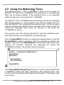
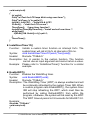
4.9 Using the Watchdog Timer
The watchdog timer of the I-7188XB(D) is fixed at 0.8 seconds for
MiniOS7 2.0. When the I-7188XB(D) is first powered on, the watchdog
timer will be always enabled. If the watchdog timer is not refreshed
within 0.8 seconds, it will reboot the I-7188XB(D).
The MiniOS7 of the I-7188XB(D) will automatically refresh the watchdog
after being powered on. User programs can call the software driver to
stop the MinOS7 from refreshing the watchdog timer, but the program
must then refresh the watchdog timer manually. If the program does not
refresh the watchdog timer every 0.8 seconds, it will cause the
I-7188XB(D) to reboot.
The program must then ask the MiniOS7 to reset the watchdog timer,
then stop and return to the MiniOS7 command prompt.
Use the EnableWDT() function to enable the watchdog timer or use the
DisableWDT() function to disable it. After the watchdog is enabled, the
program should call the RefreshWDT() function before the timer count
reaches 0.8 seconds, otherwise the watchdog will reboot the
I-7188XB(D) module. The sample code is as follows:
InitLib(); /* Initiate the 7188xb library */
EnableWDT();
while(!quit)
{
RefreshWDT();
User_function();
}
DisableWDT();
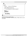
The IsResetByWatchDogTimer() function is used to check whether the
I-7188XB(D) module has been rebooted by the watchdog timer. This
function must be inserted at the beginning of program. The sample code
is as follows:
I-7188XB Series User’s Manual(Ver.1.0, Apr/2007, 7MH-020-10 ) --- 65
main()
{
InitLib();
/* Initiate the 7188xb library */
if(IsResetByWatchDogTimer())
{
/* do something here to check the system */
}
quit=0;
EnableWDT();
while(!quit)
{
RefreshWDT();
User_function();
}
Refer to the demo programs in the
CD:\Napdos\7188XABC\7188XB\Demo\BC_TC\Misc folder for more
information.
I-7188XB Series User’s Manual(Ver.1.0, Apr/2007, 7MH-020-10 ) --- 66
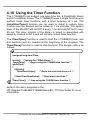
4.10 Using the Timer Function
The I-7188XB(D) can support one main time tick, 8 StopWatch timers
and 8 CountDown timers. The I-7188XB(D) uses a single 16-bit timer to
perform these timer functions, with a timer accuracy of 1 ms. The
InstallUserTimer() function can be used to install a custom timer
function and the function will be called at 1 ms intervals. The system
timer of the MiniOS7 will call INT 9 every 1 ms and call INT 0x1C every
55 ms. The timer function of the library is linked to associated with
called by hooked to INT 9 and will call any custom timer function.
The TimerOpen() function is used to start the I-7188XB(D) timer, and
this function must be inserted at the beginning of the program. The
TimerClose() function is used to stop the timer. The sample code is as
follows:
unsigned long time iTime;
InitLib(); /* Initiate the 7188xb library */
TimerOpen(); /* Begin using the 7188XB timer function */
while(!quit)
{
if(Kbhit())
TimerResetValue();
/* Reset the main time ticks to 0 */
iTime=TimerReadValue();
}
TimerClose();
/* Read main time ticks */
/* Stop using the 7188XB timer function */
Refer to the demo programs in the
CD:\Napdos\7188XABC\7188XB\Demo\BC_TC\Timer folder for more
information.
I-7188XB Series User’s Manual(Ver.1.0, Apr/2007, 7MH-020-10 ) --- 67
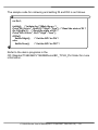
4.11 Using Digital Input and Digital output
The I-7188XB(D) provides one DI channel and one DO channel. The
SetDo1High() and SetDo1Low() functions can be used to control the
DO channel, and the GetDi1() function can be used to read the states of
the DI channel.
For DI and DO wiring information, please refer to Section 1.4.6 DI and
DO Wire Connection.
The wiring for a DO application is as follows:
DO
DI
D1+
D1CTS1
RTS1
GND
TXD1
RXD1
INIT*
D2+
D2Vs+
GND
I-7188XB Series User’s Manual(Ver.1.0, Apr/2007, 7MH-020-10 ) --- 68
The sample code for retrieving and setting DI and DO is as follows.
int Do1;
InitLib(); /* Initiate the 7188xb library */
Print("DI=%s\n\r", GetDi1()?"High":"Low"); /* Read the state of DI */
Do1=GetDo1(); /* Read the state of DO */
Print("DO=%s\n\r", Do1?"High":"Low");
if(!Do1)
SetDo1High();
/* Set the DO1 to ON */
else
SetDo1Low();
/* Set the DO1 to OFF */
Refer to the demo programs in the
CD:\Napdos\7188XABC\7188XB\Demo\BC_TC\IO_Pin folder for more
information.
I-7188XB Series User’s Manual(Ver.1.0, Apr/2007, 7MH-020-10 ) --- 69
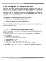
4.12 Using the I/O Expansion Bus
As there are many serial interface devices available today, the I/O
expansion bus includes both serial and parallel interfaces. The parallel
interface is very similar to an ISA bus, so the old ISA bus design can be
migrated to the I/O expansion bus with a minimum amount of alteration.
The I/O pins of the serial bus are programmable and can be
programmed as either D/I or D/O.
The features of these serial devices are as follows:
Smaller size compared to parallel devices
Lower cost compared to parallel devices
Easier to design for isolated applications
The serial interface of the I/O expansion bus makes connecting to these
serial devices very easy.
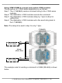
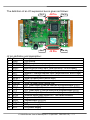
4.12.1 Definition of an I/O Expansion Bus
The I/O expansion bus of the I-7188XB(D) module can be divided into 3
groups as follows:
1. Power supply and reset signals: VCC, GND, RESET and /RESET
2. Parallel Bus:
System clock: CLOCKA
Asynchronous ready control: ARDY
Address bus: A0 ~ A7
Data bus: D0 ~ D7
Interrupt control: INT0, INT1 and INT4
Chip select and read/write strobe: /CS, /WR and /RD
3. Serial Bus: TO_0, TO_1, TI_0, TI_1, SCLK, DIO9, DIO4 and DIO14
I-7188XB Series User’s Manual(Ver.1.0, Apr/2007, 7MH-020-10 ) --- 70
The definition of an I/O expansion bus is given as follows:
Pin 2
J2 Pin
Pin 20
Pin 1
Pin 19
Pin 2
Pin 20
Pin 1
J3 Pin
Pin 19
J2 pin definition and description:
No
1
2
3
4
5
6
7
8
9
10
11
12
13
14
15
16
17
18
19
20
Name
GND
GND
CLOCKA
ARDY
INT0
INT1
VCC
RESET
GND
/RESET
TO_0
TO_1
TI_0
TI_1
SCLK
DIO9
DIO4
DIO14
VCC
VCC
Description
PCB ground
PCB ground
CPU synchronous clock output
Asynchronous ready input (level sensitive, OPEN=ready)
Channel 0 interrupt request input (asynchronous, active high)
Channel 1 interrupt request input (asynchronous, active high)
PCB power supply
Power-up reset pulse (active high)
PCB ground
Power up reset pulse (active low)
CPU Timer output 0(can be used as a programmable D/I/O)
CPU Timer output 1(can be used as a programmable D/I/O)
CPU Timer input 0 (can be used as a programmable D/I/O)
CPU Timer input 1 (can be used as a programmable D/I/O)
Common serial clock output for 7188 series modules
Programmable D/I/O bit
Programmable D/I/O bit
Programmable D/I/O bit
CPU power supply
CPU power supply
I-7188XB Series User’s Manual(Ver.1.0, Apr/2007, 7MH-020-10 ) --- 71
CLOCKA: 40M
ARDY: This pin is left OPEN for applications that do not require
the use of wait states
INT0 and INT1: These two pins are left OPEN for that do not
require an interrupt applications
TO_0 and TO_1: These pins can be used as the timer output of
the CPU or programmable DI/O
TI_0 and TI_1: These pins can be used as the timer input of the
CPU or programmable D/I/O
DIO4, DIO9 and DIO14: Programmable DI/O bit
SCLK: The I-7188XB(D) uses this signal as a CLOCK source to
drive all onboard serial devices so it is always programmed as DO.
Changing this signal to other configurations will cause serious
errors. This signal to drive external serial can be used devices
without any side effects.
J3 pin definition and description:
No
1
2
3
4
5
6
7
8
9
10
11
12
13
14
15
16
Name
A0
D0
A1
D1
A2
D2
A3
D3
A4
D4
A5
D5
A6
D6
A7
D7
17
INT4
18
19
20
/WR
/CS
/RD
Description
Address bus
Data bus
Address bus
Data bus
Address bus
Data bus
Address bus
Data bus
Address bus
Data bus
Address bus
Data bus
Address bus
Data bus
Address bus
Data bus
Interrupt request input for channel 4 (asynchronous, active
high)
Write strobe output (synchronous, active low)
Chip select output (synchronous, active low)
Read strobe output (synchronous, active low)
I-7188XB Series User’s Manual(Ver.1.0, Apr/2007, 7MH-020-10 ) --- 72
Address bus (output): A0 ~ A7
Data Bus (tri-state, bi-direction): D0 ~ D7
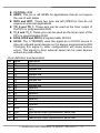
INT4: This pin is left OPEN for applications that do not require an
interrupt
/CS, /RD and /WR: These 3 signals will be synchronous to
CLOCKA (Pin3 of JP2) and asynchronous to ARDY (Pin4 of JP2)
The /CS will be active if the program needs to input/output data
from I/O address 0 to 0xff.
Note: Refer to “I/O Expansion Bus for 7188X/7188E User’s Manual”
for more information.
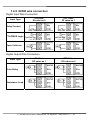
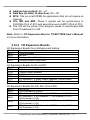
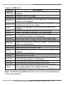
4.12.2 I/O Expansion Boards
I/O Expansion Boards for prototyping and testing:
Board
X002
X004
X005
X006
Description
Prototype Board
Self-test
Prototype Board (Small size)
Prototype Board (Large size)
I/O Expansion Boards for DI and DO:
Board
X107
X109
X110
X111
X116
X119
Description
6 DI channels + 7 DO channels
7 Relay Output channels
14 DI channels
13 DO channels
4 DI channels + 6 Relay Output channels (Without case)
7 DI channels + 7 DO channels (Without case)
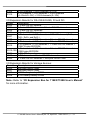
I/O Expansion Boards for A/D, D/A, DI and DO
Board
X202
X203
X303
X304
X305
Description
7 A/D channels (0~20mA)
2 DI channels + 6 DO channels + 2 A/D channels (0~20mA)
4 DI channels + 6 DO channels + 1 A/D channel (+/-5V) +
1 D/A channel (+/-5V)
4 DI channels + 4 DO channels + 3 A/D channels (+/-5V) +
1 D/A channel (+/-5V)
2 DI channels + 2 DO channels + 7 A/D channels (+/-5V) +
1 D/A channel (+/-5V)
I-7188XB Series User’s Manual(Ver.1.0, Apr/2007, 7MH-020-10 ) --- 73
X308
X310
6 DO channels + 4 A/D channels (0~10V)
3 DI channels + 3 DO channels + 2 A/D channels
(0~20mA/0~10V) + 2 D/A channels (0~10V)
I/O Expansion Boards for RS-232/422/485, DI and DO
Board
X503
X504
X505
X506
Description
1 5-wire RS-232 channel
1 5-wire RS-232 channel + 1 9-wire RS-232 channel
3 5-wire RS-232 channels
6 3-wire RS-232 channels
4 DI channels + 4 DO channels + 1 RS-422 channel (TxD+,
X507
TxD-, RxD+ and RxD-)
X508
4 DI channels + 4 DO channels + 1 5-wire RS-232 channel
X509
4 DI channels + 4 DO channels + 2 3-wire RS-232 channels
5 DI channels + 5 DO channels + 1 3-wire RS-232 channel +
X510
128K*2 bytes EEPROM
5 DI channels + 5 DO channels + 1 3-wire RS-232 channel +
X510-128
128K bytes EEPROM
X511
3 RS-485 channels
X518
8 DO channels + 1 5-wire RS-232 channels
X560
3 3-wire RS-232 channels + 8M bytes NAND Flash
I/O Expansion Boards for storage devices:
Board
X600
X601
X607
X608
Descriptions
4M bytes NAND Flash
8M bytes NAND Flash
128K battery backup SRAM
512K battery backup SRAM
Note: Refer to “I/O Expansion Bus for 7188X/7188E User’s Manual”
for more information.
I-7188XB Series User’s Manual(Ver.1.0, Apr/2007, 7MH-020-10 ) --- 74
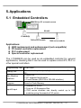
5. Applications
5.1 Embedded Controllers
MMICON (or PC or touch-screen)
RS-232
RS-485
I-7188XB(D)
7000 series module
7000 series module
Applications:
4500 replacement and enhancement (not compatible)
PC-based controller replacement
PLC replacement
Special controller replacement
The I-7188XB(D) can be used as an embedded controller for general
applications, meaning that it can be used to replace a Host PC, PLC or
other special controllers.
Programming Tool TC/BC/MSC
Debug Tool
Man Machine
Interface
Program
Via standard input/output (keyboard and monitor of a Host
PC)
• MMICON
• PC keyboard and monitor
• Touch Screen (RS-232 or RS-485 interface)
Stored in Flash Memory
Input/Output
• Onboard DI or DO
• From an I/O Expansion Bus
• 7000 series modules can directly control up to 256
modules giving thousands of I/O points
I-7188XB Series User’s Manual(Ver.1.0, Apr/2007, 7MH-020-10 ) --- 75
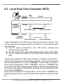
5.2 Local Real Time Controller (RTC)
RS-232
7520
RS-485
Host PC
RS-485
I-7188XB(D)
(address-1)
RS-485
7000 series module
RS-485
7000 series module
RS-485
I-7188XB(D)
(address-n)
7000 series module
7000 series module
In this configuration, the 7000 series modules act as slave devices. The
control programs are implemented in the Host PC. The operation steps
are as follows:
The PC sends commands to the 7000 series modules and
receives some input data.
The PC analyzes this input data and generates some output data
The PC sends commands to the 7000 series modules as output
data
If there are hundreds of 7000 series modules, it will take the Host PC a
long time to analyze and control these modules, so the control program
can be implemented in a local I-7188XB(D). The PC then only has to
send control arguments to the I-7188XB(D), and the I-7188XB(D) will
control the local 7000 series modules based on these control arguments.
In this way, thousands of 7000 series modules can be controlled by the
PC via the I-7188XB(D).
Some control functions are timing-critical, so the local I-7188XB(D) can
handle these functions in real time without the need for control by Host
PC.
I-7188XB Series User’s Manual(Ver.1.0, Apr/2007, 7MH-020-10 ) --- 76
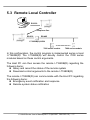
5.3 Remote Local Controller
RS-232
Host PC
Telephone line
RS-232
RS-485
I-7188XB(D)+X504
7000 series module
7000 series module
In this configuration, the control program is implemented series a local
I-7188XB(D). The I-7188XB(D) will directly control the 7000 series
modules based on these control arguments.
The Host PC can then access the remote I-7188XB(D) regarding the
following items:
Query and record the status of the remote system
Download control arguments to the remote I-7188XB(D)
The remote I-7188XB(D) can communicate with the Host PC regarding
the following items:
Emergency event notification and response
Remote system status notification
I-7188XB Series User’s Manual(Ver.1.0, Apr/2007, 7MH-020-10 ) --- 77
5.4 PLC I/O Expansion Application
PLC
COM1: RS-232
COM2: RS-485
I-7188XB(D)
7000 series modules
Most PLCs contain a Man Machine Interface that was originally
designed for MMI applications. The I-7188XB(D) can use this interface
to construct a bridge between a PLC and the 7000 series modules.
The I-7188XB(D) can directly read/write from/to the internal memory of
the PLC, meaning that the PLC can access the 7000 series input
modules as follows:
The I-7188XB(D) sends a command to the 7000 series input
modules
The I-7188XB(D) writes this data to the internal memory of the
PLC
The PLC accesses this data from its internal memory
The PLC can control the 7000 series output modules as follows:
The PLC writes data to its internal memory
The I-7188XB(D) reads the output data from the memory of the
PLC
The I-7188XB(D) sends a command to its 7000 output modules
I-7188XB Series User’s Manual(Ver.1.0, Apr/2007, 7MH-020-10 ) --- 78
In this way, the input data from the 7000 series modules can be
displayed on a touch screen. In addition the output from the 7000 series
modules can be controlled from a touch screen.
I-7188XB Series User’s Manual(Ver.1.0, Apr/2007, 7MH-020-10 ) --- 79
5.5 Radio Modem Application
Device A
Device B
Device C
Device D
SST-900/SST-2400 settings: (Device A)
RS-232
Half-duplex mode
Synchronous way
Slave state
Baud Rate=9600
Channel=3
Frequency=915.968MHz
SST-900/SST-2400 settings: (Device B/C/D)
RS-485 or RS-232
Half-duplex mode
Synchronous way
Slave state
I-7188XB Series User’s Manual(Ver.1.0, Apr/2007, 7MH-020-10 ) --- 80
Baud Rate=9600
Channel=3
Frequency=915.968MHz
As the I-7188XB(D) is an embedded controller, and is programmable, it
can be used as a bridge between the SST-900 and any external
devices, such as a PLC, a controller or other 7000 series modules.
I-7188XB Series User’s Manual(Ver.1.0, Apr/2007, 7MH-020-10 ) --- 81
5.6 An Application Using 4 COM Ports (1)
PC
PLC
COM4: RS-232
COM1: RS-232
COM3: RS-232
COM2: RS-485
I-7188XB(D)+X504
MMICON
7000 Series
SST-900/SST-2400
Radio Modem
SST-900/SST-2400
Radio Modem
7000 series modules
COM1: The PLC can access the I/O state of the 7000 series modules
COM2: Directly controls the 7000 series input/output modules
COM3: MMICON is used as the local MMI
COM4: The PC is used to monitor and record the system data.
I-7188XB Series User’s Manual(Ver.1.0, Apr/2007, 7MH-020-10 ) --- 82
5.7 An Application Using 4 COM Ports (2)
Card Reader
Modem
COM4: RS-232
COM1: RS-232
COM3: RS-232
COM2: RS-485
I-7188XB(D)+X504
TOUCH-200
Touch screen
7000 series modules
COM1: Links to the remote Host PC
COM2: Directly controls the 7000 series input/output modules
COM3: The TOUCH-200 is used as the local MMI
COM4: The Card reader is used as a standard input device.
I-7188XB Series User’s Manual(Ver.1.0, Apr/2007, 7MH-020-10 ) --- 83
Appendix A: What is MiniOS7
MiniOS7 is an embedded operating system developed by ICP DAS Co.,
Ltd. that is designed to replace ROM-DOS in 7188 series modules.
Various companies have created several brands of DOS. In all cases,
DOS (whether PC-DOS, MS-DOS or ROMDOS) is a set of commands
or code that tells the computer how to process information. DOS runs
programs, manages files, controls information processing, directs input
and output, and performs many other related functions.
MiniOS7 provides all equivalent functions of ROM-DOS while, in
addition, providing user specific functions for the I-7188XB(D).
Below is a comparison table between MiniOS7 and ROM-DOS as
follows:
Power-up time
More compact size
Support for I/O Expansion Bus
Support for ASIC Key
Flash ROM management
O.S. update (download)
Built-in hardware diagnostic functions
Direct control of 7000 series modules
Customer ODM functions
Free of charge
MiniOS7
0.1 sec
<64K bytes
Yes
Yes
Yes
Yes
Yes
Yes
Yes
Yes
ROM-DOS
4 ~ 5 sec
64K bytes
No
No
No
No
No
No
No
No
Note: ICP DAS reserves the right to change the specifications of
MiniOS7 without notice.
The typical command set for MiniOS7
Command
LED5 pos value
USE NVRAM
USE EEPROM
Description
Displays a HEX value in the specified position of 5-digit
LED
Accesses the service routine to read/write from/to the
NVRAM
Accesses the service routine to read/write from/to the
EEPROM
I-7188XB Series User’s Manual(Ver.1.0, Apr/2007, 7MH-020-10 ) --- 84
USE FLASH
USE COM2 /option
DATE [mm/dd/yyyy]
Time [hh:mm:ss]
MCB
UPLOAD
BIOS1
LOAD
DIR [/crc]
RUN fileno
Filename
DELETE or DEL
RESET
DIAG [option]
BAUD baudrate
TYPE filename [/b]
REP [/#] command
RESERVE [n]
LOADR
RUNR [option]
Accesses the service routine to read/write from/to the
Flash Memory
Accesses the service routine to send/receive to/from
COM2
Sets the date of the RTC
Sets the time of the RTC
Tests the current memory block
Stores the MiniOS7 image file in the SRAM of the
I-7188XB(D) (this command is only used to upgrade
MiniOS7)
Stores the MiniOS7 image file in the Flash memory of
the I-7188XB(D) (this command only used to upgrade
MiniOS7)
Downloads the user program file to the Flash Memory
of the I-7188XB(D)
Lists the information of all files stored in the Flash
Memory of the I-7188XB(D)
Executes the file with the prescribed file number
Executes the file with the prescribed file name
Deletes all files stored in the Flash Memory.
Resets the CPU
Performs hardware diagnostics
Sets a new value for the Baud Rate of COM1
Lists the contents of a file
Repeats the execution of the same command # times
Reserve n Flash Memory sectors for a program file
Downloads files to the SRAM
Runs the program stored in the SRAM of the
I-7188XB(D) (downloaded using the LOADR command)
Reads data from the hardware Port
I/INP/IW/INPW port
O/OUTP/OW/OUTPW
Outputs data to the hardware Port
port value
More ……
Note: For more detailed information regarding MiniOS7, please refer to
CD:\Napdos\MiniOS7\document\Lib_Manual_For_7188XABC\index.htm or
I-7188XB Series User’s Manual(Ver.1.0, Apr/2007, 7MH-020-10 ) --- 85
http://ftp.icpdas.com/pub/cd/8000cd/napdos/minios7/document/lib_man
ual_for_7188xabc/index.htm
I-7188XB Series User’s Manual(Ver.1.0, Apr/2007, 7MH-020-10 ) --- 86
Appendix B: MiniOS7 Utility and 7188XW
Both the MiniOS7 Utility and 7188xw.exe application will allow users to
easily upgrade to the latest version of MiniOS7. The MiniOS7 Utility and
7188xw.exe application can be used to perform essential configuration
functions and for downloading programs to the MiniOS7 embedded in
the I-7188XB(D) controller.
MiniOS7 Utility
The MiniOS7 Utility program provides three main functions:
Upgrade the MiniOS7 image
Download program files to the Flash Memory
Configure the COM port settings
MiniOS7 utility location
The MiniOS7 utility is located in the
CD:\NAPDOS\MINIOS7\UTILITY\MiniOS7_utility folder on the CD or at
http://ftp.icpdas.com/pub/cd/8000cd/napdos/minios7/utility/minios7_utility/
on the web
Installation procedure
Step 1: Locate and execute minios7_utility_v2000.exe from the
CD:\Napdos\MiniOS7\utility\MiniOS7_utility\ folder.
Step 2: After completing the installation, a new folder, 7188E, will be
added to the programs section of the start menu. Clicking on
this folder will allow access to the MiniOS7 Utility files. See the
diagram below for details.
I-7188XB Series User’s Manual(Ver.1.0, Apr/2007, 7MH-020-10 ) --- 87
I-7188XB Series User’s Manual(Ver.1.0, Apr/2007, 7MH-020-10 ) --- 88
7188XW
The 7188xw.exe application is the main utility for the I-7188XB(D), and
can be used to perform the following functions:
Download user program files from a Host PC into the memory
unit of the I-7188XB(D) module.
Download the MiniOS7 image file from a Host PC into the
Flash Memory of the I-7188XB(D) controller and upgrade the
MiniOS7.
Show a debug string on the monitor of a Host PC
Three standard output library functions, such as Putch function,
Print and Puts, will allow a main control unit to send an output
string to the monitor of a Host PC.
Enter data into I-7188XB(D) module using the Host PC
keyboard
Three standard input library functions, such as Getch, Scanf and
LineInput, will allow the main control unit to read keyboard input
from a Host PC.
7188xw.exe location
The 7188xw.exe is located in the CD:\Napdos\MiniOS7\utility\ folder or at
http://ftp.icpdas.com/pub/cd/8000cd/napdos/minios7/utility/ on the web.
7188xw.exe command line options for MiniOS7
Option
Description
/c#
/b#
/s#
Uses COM# of the Host PC
Sets the Baud Rate for the COM port on the Host PC (default is
115200)
Sets the number of display rows on the screen (default is 25,
max. is 50)
7188xw.exe Hot-key
Command Description
F1
Alt_F1
Ctrl_F1
Shows the 7188xw.exe help messages
Shows the 7188xw.exe help messages using the Chinese (Big5)
character set
Shows the 7188xw.exe help messages using the Chinese
(GB2312) character set
I-7188XB Series User’s Manual(Ver.1.0, Apr/2007, 7MH-020-10 ) --- 89
Alt_1
Alt_2
Alt_3
Alt_4
Alt_5
Alt_6
Alt_7
Alt_8
Alt_9
Alt_A
Alt_C
Alt_D
Alt_T
Alt_E
Alt_H
Alt_L
Alt_X
F2
F5
F6
Ctrl_F6
F8
F9
Alt_F9
Uses COM1 on the Host PC
Uses COM2 on the Host PC
Uses COM3 on the Host PC
Uses COM4 on the Host PC
Uses COM5 on the Host PC
Uses COM6 on the Host PC
Uses COM7 on the Host PC
Uses COM8 on the Host PC
Uses COM9 on the Host PC
Switches between normal mode and ANSI-Escape-code-support
mode
Switches to command mode. Supports commands:
b#: Sets a new Baud Rate for the COM ports on the Host PC
c#: Uses COM# on the Host PC
n/e/o: Sets the parity to none/even/odd
5/6/7/8: Sets the data bits to 5/6/7/8
p#: Sets working directory of the Host PC
q: Quits command mode
Sets the date of the RTC to the date on the Host PC
Set the time of the RTC to the time on the Host PC
Used to download a file to memory. Alt_E should be pressed only
after the “Press ALT_E to download file!” message is shown on
the screen.
Toggles between Hex/ASCII display mode
Toggles between normal/line mode. In line mode, all characters
pressed will not be sent to the COM Port until the ENTER key is
pressed, and it is designed for testing 7000 series modules
Quits the 7188xw.exe application
Sets the file name for downloading (without initiating a download
operation)
Runs the program specified by F2 and arguments set by F6
Sets the arguments of the execution file set by F2. (10 arguments
maximum. If set to less than 10 arguments, add ‘*’ to end)
Clears the screen
F8=F9+F5
Downloads the file specified by F2 to the FLASH memory
Downloads all files specified by ALT_F2 to the FLASH memory
I-7188XB Series User’s Manual(Ver.1.0, Apr/2007, 7MH-020-10 ) --- 90
F10
Alt_F10
Ctrl_B
Downloads the file specified by F2 to the SRAM and executes it
Downloads all files specified by ALT_F2 to the SRAM memory
Sends a BREAK signal to the COM port of the Host PC that is
currently being used by 7188xw.exe
More…
For more detailed information regarding the 7188xw.exe application,
please refer to the index.htm file in the
CD:\Napdos\MiniOS7\document\Lib_Manual_For_7188XABC\ folder or at
http://ftp.icpdas.com.tw/pub/cd/8000cd/napdos/minios7/document/lib_
manual_for_7188xabc/ on the web.
Downloading a file to the I-7188XB(D) controller using the
7188xw.exe application
Step 1: Power-off the I-7188XB(D). Connect the INIT* pin to the GND
pin and power-on the I-7188XB(D) at the same time.
Step 2: After the I-7188XB(D) has been switched on, disconnect the
INIT* pin from the GND pin.
Step 3: Open an MS-DOS command prompt window using the steps
shown bellow.
I-7188XB Series User’s Manual(Ver.1.0, Apr/2007, 7MH-020-10 ) --- 91
Step 4: Type “cd c:\7188XB\Demo\BC_TC\Hello\Hello_C\” then press
<Enter>. (Assume user copy the 7188XB folder to C drive letter.
Refer to Step2 in Sec.2.1)
Step 5: Execute the 7188xw.exe application as shown in the following
figure.
I-7188XB Series User’s Manual(Ver.1.0, Apr/2007, 7MH-020-10 ) --- 92
Step 6: Press <F2> and then type the filename “Hello.exe” and press
<Enter>.
Step 7: Press <F8> to download the Hello.exe file to the I-7188XB(D)
and execute the program.
I-7188XB Series User’s Manual(Ver.1.0, Apr/2007, 7MH-020-10 ) --- 93
Notes: A description of the Hotkey functions is as follows:
F8: Download a file to FLASH Memory, and then execute the program
F9: Download a file to FLASH Memory.
F10: Download a file to SRAM, and then execute the program.
Step 8: Type “dir” and press <Enter> to check that the files are stored in
the Flash Memory of the I-7188XB(D).
Step 9: Type “del /y” and press <Enter> to delete all files stored in the
Flash Memory of the I-7188XB(D).
I-7188XB Series User’s Manual(Ver.1.0, Apr/2007, 7MH-020-10 ) --- 94
Note: The MiniOS7 only supports the delete all command. Individual
files cannot be selected for deletion.
Step 10: Press <Alt + X> to quit the MiniOS7.
Upgrading MiniOS7 using the 7188xw.exe application
Step 1: Connect the I-7188XB(D) to the COM Port of the Host PC using
the CA0910 cable. Refer to the wiring diagram in Section 2.2 for
details.
Step 2: Determine the latest version of the MiniOS7 image file.
The format of the image file name is: TTYYMMDD.img
TT: TYPE of product.
YY: Year that this image was released
MM: Month that this image was released
DD: Day that this image was released
Note: The MiniOS7 image file can be found in the
CD:\NAPDOS\MiniO7\ directory on the companion CD. The latest
MiniOS7 version can be downloaded from:
http://ftp.icpdas.com/pub/cd/8000cd/napdos/7188xabc/7188xb/os_image/
Step 3: From the Host PC, go to the directory where the image file is
stored, then execute the 7188xw.exe application to connect the
Host PC to the I-7188XB(D) controller.
Step 4: Use the “UPLOAD” command, then press <ALT + E> after the
“Press ALT_E to download file!” message is shown on the
screen.
I-7188XB Series User’s Manual(Ver.1.0, Apr/2007, 7MH-020-10 ) --- 95
Step 5: Type the image filename (for example: xb050701.img) then
press <ENTER>.
Step 6: Wait for the upload to finish. (The image file will be stored in the
SRAM.)
Step 7: Type the “bios1” command in the I-7188XB(D) command line.
(The OS will check the image file stored in the SRAM, and then
display the version information. If the image file is correct, it will
be written to the Flash Memory.)
I-7188XB Series User’s Manual(Ver.1.0, Apr/2007, 7MH-020-10 ) --- 96
Step 8: It will take about 10 seconds to upgrade MiniOS7. After the
update has finished, the system will automatically reboot. If this
does not occur, the system must be rebooted manually.
Step 9: Type the “ver” command to check the MiniOS7 version number.
I-7188XB Series User’s Manual(Ver.1.0, Apr/2007, 7MH-020-10 ) --- 97
Appendix C: Comparison Table
Feature comparison table between the 7188 and the 7188X series:
I-7188XA(D)
I-7188XB(D)
I-7188XC(D)
CPU clock
80188, 40MHz
80188, 40MHz
SRAM
512K
256K(I-7188XB)
128K
512K(I-7188XB/512)
Flash Memory
512K
512K
RS-232 with
modem control or
RS-485 with
internal self-tuner
RS-485 with
internal self-tuner,
3000V isolation
COM1
COM2
80188, 20MHz
256K
(512K for ODM)
I-7188(D)
80188, 40MHz
256K
256K/512K
RS-232 or RS-485 RS-232 or RS-485 RS-232 with
with internal
with internal
modem control or
self-tuner
self-tuner
RS-485
RS-485 with
self-tuner inside
RS-485 with
self-tuner inside
RS-485
COM3
RS-232 (TxD, RxD) No COM
No COM
RS-232 (TxD, RxD)
COM4
RS-232 (Txd, Rxd) No COM
No COM
RS-232 (TxD, RxD)
User defined pins
0
14
3
0
Modem control
COM1
No
No
COM1
RTC
64-bit hardware
unique serial
number
EEPROM
Yes
Yes
No
Yes
Yes
Yes
No
No
2K bytes
2K bytes
2K bytes
2K bytes
D/I (3.5V~30V)
2 channels
1 channel
2 channels
0
D/O (100mA, 30V) 2 channels
1 channel
3 channels
0
I/O expansion bus
Support for ASIC
Key
Operating system
Programming
language
Program
download Port
Yes
Yes
Yes
No
Yes
Yes
Yes
No
MiniOS7
MiniOS7
MiniOS7
MiniOS7
TC/MSC/BC
TC/MSC/BC
TC/MSC/BC
TC/MSC/BC
COM4
COM1
COM1
COM4
I-7188XB Series User’s Manual(Ver.1.0, Apr/2007, 7MH-020-10 ) --- 98
Appendix D: Library Function List
The table below lists the most commonly used functions. For more
details of all functions, refer to the instructions in the
CD:\Napdos\MiniOS7\document\Lib_Manual_For_7188XABC\index_e.htm file or
http://ftp.icpdas.com/pub/cd/8000cd/napdos/minios7/document/lib_man
ual_for_7188xabc/index_e.htm on the web.
Type 1: Standard IO
Function
Description
Checks if any keyboard input data is currently available in the input
buffer of COM1.
Waits until a single character is received from keyboard input.
Getch
Returns a single character to the input buffer of COM1.
Ungetch
Sends a single character to COM1.
Putch
Sends a string to COM1.
Puts
Retrieves formatted data such as scanf in the C language (Cannot
Scanf
used on MSC/VC++, only TC/BC)
Prints formatted data such as printf in the C language.
Print
ReadInitPin Reads the status of the INIT* pin.
Inputs a single line from StdInput.
LineInput
There are more user functions for Standard IO. For more detailed
information, please refer to the 7188xb.h file and
…More…
Kbhit
CD:\Napdos\MiniOS7\document\Lib_Manual_For_7188XABC\index.htm
I-7188XB Series User’s Manual(Ver.1.0, Apr/2007, 7MH-020-10 ) --- 99
Note: The Print and printCom function cannot be used simultaneously
in the same program.
Kbhit()
Function:
Checks whether any keyboard input data is currently
available in the input buffer.
Syntax:
int Kbhit(void);
Header:
#include ”7188xb.h”
Description: Checks if any data is currently available in the input
buffer.
Return:
0: For no data input.
Other: There is data in the input buffer, and the return
value is the next data in the buffer. If the next data
is “\0”, the function will return -1 (0xFFFF).
Example:
#include “7188xb.h”
void main()
{
int quit=0, data;
InitLib();
Puts("\n\rPress any key to show ASCII ('Q' to quit):\n\r");
while(!quit){
if(Kbhit()){
data=Getch();
if(data=='Q') quit=1;
Putch(data);
Print(" ASCII is: %d\n\r", data);
Puts("\n\rPress any key to show ASCII ('Q' to quit):\n\r");
}
}
}
Getch()
Function: Waits until a character is received from keyboard input.
Syntax:
int Getch(void);
Header:
#include ”7188xb.h”
Description: Reads a single character from the input buffer. If there is
no input in the data buffer, the function will wait until the
input buffer receives some data.
Return Value: 0 to 255.
I-7188XB Series User’s Manual(Ver.1.0, Apr/2007, 7MH-020-10 ) --- 100
Example:
Please refer to “Kbhit()” for an example.
Ungetch()
Function: Put a single character to the input buffer.
Syntax:
int Ungetch(int data);
Header:
#include ”7188xb.h”
Description: If there is no data in the input buffer when Ungetch() is
called, next time the Getch() function is called, it will
return the data.
Data: 0 to 255. If the data is > 255, only the low byte will
be sent.
Return:
On success, returns NoError. On error (i.e. the buffer is
full) returns 1.
Example: Please refer to “Kbhit()” for an example of Getch().
Putch()
Function: Displays a single character on the screen.
Syntax:
void Putch(int data);
Header:
#include ”7188xb.h”
Description: Data: 0 to 255. If the data is > 255, only the low byte will
be sent.
Example: Please refer to “Kbhit()” for an example.
Puts()
Function: Displays a string on the screen.
Syntax:
void Puts(char *str);
Header:
#include ”7188xb.h”
Description: Puts will call Putch() to send the string.
str: The pointer to the string to be sent.
Example: Please refer to “Kbhit()” for an example.
Scanf()
Function:
Scans a character from the input and is similar to the
scanf() function. (This function cannot be used with MSC
/VC++)
Syntax:
int Scanf(char *fmt, ...);
Header:
#include ”7188xb.h”
Description: Returns the number of input fields successfully scanned,
I-7188XB Series User’s Manual(Ver.1.0, Apr/2007, 7MH-020-10 ) --- 101
Return:
Example:
converted, and stored. The return value does not include
any scanned fields that were not stored.
0: No fields were stored.
EOF: Attempts to read have reached the end of the
string.
See CD:\Napdos\7188XABC\7188XB\Demo\MSC\COM_
Ports\C_Style_IO\
Print()
Function:
Prints a formatted character to the screen, and is similar
to the printf() function in the C language.
Syntax:
int Print(char *fmt,...);
Header:
#include ”7188xb.h”
Description: This function is used instead of printf(), and the only
difference between Print() and printf() is that Print() does
not convert the characters “\n” to “\n” + “\r”. That is “\n”
only sends the code 0x0A, not 0x0A + 0x0D, so “\n\r”
has to be used for “new line and return”. The printed
message is sent to COM4. (Default parameters are
115200, N, 8, 1)
Input Parameters: Please refer to the standard function printf() in the
C language.
Return:
The character number to be sent out.
Example: Please refer to “Kbhit()” for an example.
I-7188XB Series User’s Manual(Ver.1.0, Apr/2007, 7MH-020-10 ) --- 102
Type 2: COM port
Function
Description
Installs the COM Port driver. The COM Port number is not
InstallCom
assigned
InstallCom1 Installs the driver for COM1
InstallCom2 Installs the driver for COM2
Uninstalls the drivers for the COM Port. The COM Port
RestallCom
number is not assigned
Uninstalls the driver for COM1. Assigned to COM1
RestallCom1
RestallCom2 and etc are similar
Check if Com has data. The COM Port number is not
IsCom
assigned
IsCom1
Checks if any data is waiting in the COM1 buffer
IsCom2… Checks if any data is waiting in the COM2 buffer
Clears all the data currently stored in the COM Port Buffer.
ClearCom
The COM Port number is not assigned
ClearCom1 Clears all the data currently stored in the COM1 buffer
ClearCom2 Clears all the data currently stored in the COM2 buffer
Reads the data from COM Port buffer. The COM Port
ReadCom
number is not assigned
ReadCom1 Reads data from the COM1 buffer
ReadCom2 Reads data from the COM2 buffer
Sends data to the COM Port. The COM Port number is not
ToCom
assigned
ToCom1
Sends data to the COM1
ToCom2
Sends data to the COM2
Prints any data currently stored in the COM Port buffer.
printCom
The COM Port number is not assigned
printCom1 Prints any data currently stored in the COM1
printCom2 Prints any data currently stored in the COM2
There are more functions available for use with COM
…More…
Ports. Please refer to the 7188xb.h file and
CD:\Napdos\MiniOS7\document\Lib_Manual_For_7188XABC\index.htm
Note: The Print and printCom function cannot be used simultaneously
in the same program.
I-7188XB Series User’s Manual(Ver.1.0, Apr/2007, 7MH-020-10 ) --- 103
InstallCom()
Function: Installs the driver for the COM Port.
Syntax:
int InstallCom(int port, unsigned long baud, int data,
int parity, int stop);
Header:
#include ”7188xb.h”
Description: Installs the driver for the COM Port. The COM Port
number is not assigned and can be modified using the
“port” parameter.
port: assigns the COM port number
baud: Baud Rate, the default Baud Rate for the
I-7188XB(D) is 115200
Example:
#include “7188xb.h”
void main()
{
int quit=0, data, i, port=1; /*port=1, uses COM1*/
InitLib();
InstallCom(port,115200,8,0,1); /*installs the COM port driver*/
for(i=0; i<10; i++)
printCom(port,"Test %d\n\r",i); /*prints data to the COM Port*/
while(!quit) {
if(IsCom(port)) { /*checks if any data is in the COM Port buffer*/
data=ReadCom(port); /*reads data from the COM Port buffer*/
ToCom(port,data); /*sends data to the COM Port buffer*/
ClearCom(port); /*clears all the data in the COM Port buffer*/
if(data=='Q') quit=1; /*if 'Q' is received, exit the program*/
}
}
RestoreCom(port); /*uninstalls the driver for COM Port */
}
InstallCom1()
Function: Installs the driver for COM1.
Syntax:
int InstallCom1(unsigned long baud, int data, int
parity, int stop);
Header:
#include ”7188xb.h”
Description: Installs the driver for COM1, and is assigned to COM1
baud: Baud Rate, the default Baud Rate for the
I-7188XB(D) is 115200
Example:
I-7188XB Series User’s Manual(Ver.1.0, Apr/2007, 7MH-020-10 ) --- 104
#include “7188xb.h”
void main()
{
int quit=0,data;
InitLib();
InstallCom1(115200,8,0,1); /*install the driver for COM1*/
while(!quit) {
if(IsCom1()) { /*checks if any data is in the COM1 buffer*/
data=ReadCom1(); /*reads data from COM1*/
ToCom1(data); /*sends data to COM1*/
if(data==’q’) quit=1; /*if ‘q’ is received, exit the program*/
}
}
RestoreCom1(); /*uninstalls the driver for COM1*/
}
RestoreCom()
Function: Uninstalls the driver for the COM Port. The COM Port
number is not assigned.
Syntax:
int RestoreCom(int port);
Header:
#include ”7188xb.h”
Description: Uninstalls the driver for the COM Port. The COM Port
number is not assigned and can be modified using the
“port” parameter.
port: assigns the COM Port number
Example: Please refer to “InstallCom()” for an example.
RestoreCom1()
Function: Uninstall the driver for COM1.
Syntax:
int RestoreCom1(void);
Header:
#include ”7188xb.h”
Description: Uninstall the driver for COM1 and is assigned to COM1
Example: Please refer to “InstallCom1()” for an example.
IsCom()
Function:
Syntax:
Header:
Checks whether there is any data stored in the COM Port
buffer. The COM Port number is not assigned.
int IsCom(int port);
#include ”7188xb.h”
I-7188XB Series User’s Manual(Ver.1.0, Apr/2007, 7MH-020-10 ) --- 105
Description: Checks whether there is any data stored in the COM
Port buffer. The COM Port number is not assigned and
can be modified using the “port” parameter.
port: assigns the COM port number
Example: Please refer to “InstallCom()” for an example.
IsCom1()
Function: Checks whether there is any data stored in the buffer of
COM1.
Syntax
int IsCom1(void);
Header:
#include ”7188xb.h”
Description: Checks whether there is any data stored in the buffer of
COM1
Example: Please refer to “InstallCom1()” for an example.
ReadCom()
Function: Reads data from the COM Port buffer. The COM Port
number is not assigned.
Syntax:
int ReadCom(int port);
Header:
#include ”7188xb.h”
Description: Reads data from the COM Port buffer. The COM Port
number is not assigned and can be modified using the
“port” parameter.
port: assigns the COM Port number
Example: Please refer to “InstallCom()” for an example.
ReadCom1()
Function: Reads data from the buffer of COM1.
Syntax:
int ReadCom1(void);
Header:
#include ”7188xb.h”
Description: Reads data from the buffer of COM1. Assigned to
COM1.
Example: Please refer to “InstallCom1()” for an example.
ClearCom()
Function: Clears the data currently stored in the COM Port buffer.
The COM Port number is not assigned.
Syntax:
int ClearCom(int port);
I-7188XB Series User’s Manual(Ver.1.0, Apr/2007, 7MH-020-10 ) --- 106
Header:
#include ”7188xb.h”
Description: Clears the data currently stores in the COM Port buffer.
The COM Port number is not assigned and can be
modified using the “port” parameter.
port: assigns the COM Port number
Example: Please refer to “InstallCom()” for an example.
ClearCom1()
Function: Clears the data currently stored in the buffer of COM1.
Syntax:
int ClearCom1(void);
Header:
#include ”7188xb.h”
Description: Clears the data currently stored in buffer of COM1.
Assigned to COM1.
Example: Please refer to “InstallCom1()” for an example.
ToCom()
Function:
Sends data to the COM Port. The COM Port number is
not assigned.
Syntax:
int ToCom(int port);
Header:
#include ”7188xb.h”
Description: Sends data to the COM Port. The COM Port number is
not assigned and can be modified using the “port”
parameter.
port: assigns the COM Port number
Example: Please refer to “InstallCom()” for an example.
ToCom1()
Function: Sends data to COM1.
Syntax:
int ToCom1(void);
Header:
#include ”7188xb.h”
Description: Sends data to COM1. Assigned to COM1.
Example: Please refer to “InstallCom1()” for an example.
printCom()
Function: Prints data to COM and PC. The COM Port number is not
assigned.
Syntax:
int printCom(int port,char *fmt,...);
I-7188XB Series User’s Manual(Ver.1.0, Apr/2007, 7MH-020-10 ) --- 107
Header:
#include ”7188xb.h”
Description: Prints data from the COM Port buffer. The COM Port
number is not assigned and can be modified using the
“port” parameter. Produces a formatted output, similar to
printf() from the standard C library.
Example: Please refer to “InstallCom()” for an example.
printCom1()
Function: Prints data from the buffer of COM1.
Syntax:
int printCom_1(char *fmt,...);
Header:
#include ”7188xb.h”
Description: Prints data from the buffer of COM1. Produces a
formatted output, similar to printf() from standard C
library.
Example: This function is similar to printCom(). Please refer to
“InstallCom()” for an example.
I-7188XB Series User’s Manual(Ver.1.0, Apr/2007, 7MH-020-10 ) --- 108
Type 3: EEPROM
Function
EE_WriteEnable
EE_MultiWrite
EE_WriteProtect
EE_MultiRead
…More…
Description
Sets the EEPROM to write-enable mode
Writes data to the EEPROM
Sets the EEPROM to write-protect mode
Reads data from the EEPROM
There are many other user functions related to
EEPROM. Please refer to the 7188xb.h header file
and the user manual on the enclosed CD, which can
be found at
CD:\Napdos\MiniOS7\document\Lib_Manual_For_7188XABC\ind
ex.htm for more detailed information.
EE_WriteEnable ()
Function: Sets the EEPROM to write-enable mode.
Syntax:
void EE_WriteEnable (void);
Header:
#include ”7188xb.h”
Description: Sets the EEPROM to write-enable mode. The EEPROM
is in write-protect mode by default. EE_WriteEnable()
must be called before writing data to the EEPROM.
Example:
#include <7188xb.h>
void main()
{
Int data=55, data2;
InitLib();
EE_WriteEnable ();
EE_MultiWrite(1,10,1,&data);
EE_WriteProtect();
EE_MultiRead(1,10,1,&data2);
Print("data=%d, Data2=%d", data,data2);
}
EE_MultiWrite ()
Function: Writes data to the EEPROM
Syntax:
int EE_MultiWrite(int Block,unsigned Addr,int
no,char *Data);
Header:
#include ”7188xb.h”
Description: Writes multi-byte of data to the EEPROM.
I-7188XB Series User’s Manual(Ver.1.0, Apr/2007, 7MH-020-10 ) --- 109
Block: 0 to 7 (a total of 8 blocks).
Addr: 0 to 255 (each block can contain 256 bytes).
no: 1 to 16
Data: The start address of buffer that the data is stored.
Return Value: On success, returns NoError.
On error, returns -1. It is say EEPROM is busy, Block is
invalid or Addr is invalid.
Example: Please refer to “EE_WriteEnable()” for an example.
EE_WriteProtect ()
Function: Sets the EEPROM to write-protect mode
Syntax:
void EE_WriteProtect(void);
Header:
#include ”7188xb.h”
Description: Sets the EEPROM to write-protect mode. The EEPROM
is in write-protect mode by default. EE_WriteEnable()
must be called before writing data to the EEPROM. After
writing the data, it is recommended that EE_WriteProtect
() be called to return the EEPROM to write-protect mode.
Example: Please refer to “EE_WriteEnable()” for an example.
EE_MultiRead ()
Function: Reads data from the EEPROM
Syntax:
int EE_MultiRead(int StartBlock,unsigned
StartAddr,int no,char *databuf);
Header:
#include ”7188xb.h”
Description: Reads multi-byte data from the EEPROM.
StartBlock: 0 to 7 (a total of 8 blocks).
StartAddr: 0 to 255 (each block can contain 256 bytes).
no: 1 to 2048
databuf: The address to store data
Return Value: On success, returns NoError.
On error, returns -1. It is say EEPROM is busy, Block is
invalid or Addr is invalid.
Example: Please refer to “EE_WriteEnable()” for an example.
I-7188XB Series User’s Manual(Ver.1.0, Apr/2007, 7MH-020-10 ) --- 110
Type 4: NVRAM and RTC
Function
Description
ReadNVRAM Reads data from the NVRAM.
WriteNVRAM Writes data to the NVRAM.
GetTime
Gets the system time from the RTC.
SetTime
Sets the system time for the RTC
GetDate
Gets the system date from the RTC
SetDate
Sets the system date for the RTC
GetWeekDay Gets the day of the week from the RTC.
There are many other functions related to the NVRAM and
the RTC. Please refer to the 7188xb.h header file and the
…More…
user manual on the enclosed CD, which can be found at
CD:\Napdos\minios7\document\lib_manual_for_7188xabc\index.htm
for more detailed information.
ReadNVRAM()
Function: Reads data from the NVRAM.
Syntax:
int ReadNVRAM(int addr);
Header:
#include ”7188xb.h”
Description: Reads one byte of data from the NVRAM.
addr: 0 to 30, a total of 31 bytes.
Return Value: On success, returns the data (0-255) stored at the
specified address.
On error, returns the AddrError (-9).
Example:
#include “7188xb.h”
void main()
{
int data=55, data2;
InitLib();
WriteNVRAM(0,data);
data2=ReadNVRAM(0); /* now data2=data=55 */
Print("data=%d, data2=%d",data,data2);
}
WriteNVRAM()
Function: Writes data to the NVRAM.
Syntax:
int WriteNVRAM(int addr, int data);
I-7188XB Series User’s Manual(Ver.1.0, Apr/2007, 7MH-020-10 ) --- 111
Header:
#include ”7188xb.h”
Description: Writes one byte of data to the NVRAM.
addr: 0-30.
data: One byte of data (0-255).
If the data>255, only the low byte will be written to the
NVRAM.
Return Value: On success, returns NoError.
On error, returns the AddrError (-9).
Example: Please refer to “ReadNVRAM()” for more detailed
information.
GetTime()
Function: Retrieves the system time from the RTC.
Syntax:
void GetTime(int *hour, int *minute, int *sec);
Header:
#include ”7188xb.h”
Description: hour: The address used to save the hour (0-23) data.
minute: The address used to save the minute (0-59)
data.
sec: The address used to save the second (0-59) data.
Example:
#include “7188xb.h”
void main()
{
int year, month, day, hour, min, sec, wday;
InitLib();
SetDate(2006,1,12); /*sets the system date for the RTC*/
SetTime(15,35,50); /*sets the system time for the RTC*/
SetWeekDay(4); /*sets the system day of the week for the RTC*/
GetDate(&year,&month,&day); /*reads the system date from the RTC*/
GetTime(&hour,&min,&sec); /*reads the system time from the RTC*/
wday=GetWeekDay();
Print("Date=%02d/%02d/%04d(%d) Time=%02d:%02d:%02d\n\r",
month,day,year,wday,hour,min,sec);
}
SetTime()
Function: Sets the system time to the RTC
Syntax:
int SetTime(int hour,int minute,int sec);
Header:
#include ”7188xb.h”
I-7188XB Series User’s Manual(Ver.1.0, Apr/2007, 7MH-020-10 ) --- 112
Description: hour: 0-23.
minute: 0-59.
sec: 0-59.
Return Value: On success, returns NoError.
On error, returns the TimeError (-19).
Example: Please refer to “GetTime()” for more detailed information.
GetDate()
Function: Reads the system date from the RTC
Syntax:
void GetDate(int *year,int *month,int *day);
Header:
#include ”7188xb.h”
Description: year: 2000-2080
month: 1-12
day: 1-31
Example: Please refer to “GetTime()” for more detailed information.
SetDate()
Function: Sets the system date to the RTC
Syntax:
int SetDate(int year,int month,int day);
Header:
#include ”7188xb.h”
Description: year: 2000-2080
month: 1-12
day: 1-31
Return Value: On success, returns NoError.
On error, returns DateError (-18).
Example: Please refer to “GetTime()” for more detailed information.
GetWeekDay()
Function: Reads the weekday from the RTC.
Syntax:
int GetWeekDay(void);
Header:
#include ”7188xb.h”
Description: Reads the weekday from the RTC.
Return Value: 0=>Sunday
1-6=>Monday to Saturday.
Example: Please refer to “GetTime()” for more detailed information.
Note: GetWeekDay() does not check whether the weekday is correct
or not, only reads the value from the RTC. When using the MiniOS7
I-7188XB Series User’s Manual(Ver.1.0, Apr/2007, 7MH-020-10 ) --- 113
“date” command to set the date, the MiniOS7 will calculate the correct
weekday and set the RTC. If SetDate() is called, it will also calculate
the correct weekday and set the RTC. However, if SetWeekDay() is
called, the function must calculate the correct weekday itself.
I-7188XB Series User’s Manual(Ver.1.0, Apr/2007, 7MH-020-10 ) --- 114
Type 5: Flash Memory
Function
Description
FlashReadId Retrieces the information about Flash.
FlashErase Erases a single sector of the Flash memory.
FlashWrite Writes one byte of data to the Flash memory.
FlashRead Reads one byte of data from the Flash memory.
There are many other functions related to the Flash
memory. Please refer to the 7188xb.h header file and the
…More…
user manual on the enclosed CD, which can be found at
CD:\Napdos\minios7\document\lib_manual_for_7188xabc\index.htm
for more detailed information.
The Flash memory used in I-7188XB(D) series modules has a capacity
of 512K bytes. The MiniOS7 will use the last 64K bytes, and the
remaining space can be used to store custom programs or data.
Application developers can use these functions to write data to the
Flash memory. When writing data to the Flash memory, data only be
written from “1” to “0”, and cannot be written from “0” to “1”. So, before
writing data to the Flash memory, must be erased first. The erase
process will cause all data to revert to 0xFF, that is all data bits will be
“1”. Only then can data be written. The FlashErase() function is used to
erase one sector (64K bytes) each time.
FlashReadId()
Function: Retrieves the information about Flash.
Syntax:
int FlashReadId(void);
Header:
#include ”7188xb.h”
Description: Reads the Flash memory device code (high byte) and
manufacturer code (low byte).
Return Value: 0xA4C2 (MXIC 29f040), 0xA401 (AMD 29f040)
Example: See CD:\Napdos\7188XABC\7188XB\Demo\BC_TC\
Memory\
FlashErase()
Function: Erases a single sector of the Flash memory.
Syntax:
int FlashErase(unsigned seg);
I-7188XB Series User’s Manual(Ver.1.0, Apr/2007, 7MH-020-10 ) --- 115
Header:
#include ”7188xb.h”
Description: Erases a single sector (64K bytes) of the Flash memory.
The value of all data on that sector will revert to 0xFF.
seg: 0x8000, 0x9000, 0xA000, 0xB000, 0xC000,
0xD000 or 0xE000.
Return Value: On success, returns NoError (0).
On error, returns TimeOut (-5).
Example: Please refer to “\Demo\BC_TC\Memory\Flash\ FLASH.C”
for more detailed information.
Note: Segment 0xF000 is used to store the MiniOS7, if attempting to
erase segment 0xF000, FlashErase() will do nothing.
FlashWrite()
Function: Writes one byte of data to Flash memory.
Syntax:
int FlashWrite(unsigned int seg, unsigned int offset,
char data);
Header:
#include ”7188xb.h”
Description: seg: 0x8000, 0x9000, 0xA000, 0xB000, 0xC000,
0xD000 or 0xE000.
offset: 0 to 65535 (0xffff).
data: 0 to 255 (8-bit data).
Return Value: On success, returns NoError(0).
On error, returns TimeOut(-5) or SegmentError(-12).
Example:
#include “7188xb.h”
void main()
{
int data=0xAA55, data2;
char *dataptr;
InitLib();
dataptr=(char *)&data;
FlashWrite(0xd000,0x1234, *dataptr++);
/*writes data to the Flash
memory*/
FlashWrite(0xd000,0x1235, *dataptr);
dataptr=(char *)&data2;
/*reads data from the Flash memory*/
*dataptr=FlashRead(0xd000, 0x1234);
*(dataptr+1)=FlashRead(0xd000, 0x1235);
}
I-7188XB Series User’s Manual(Ver.1.0, Apr/2007, 7MH-020-10 ) --- 116
Note: When writing data to the Flash memory, the data bit only can
be changed from 1 to 0 and cannot be written from “0” to “1”.
FlashWrite() does not check the status, and just writes the data. If an
attempt is made to change the data from 0 to 1, a TimeoutError will
occur. After calling FlashErase() data can be written again.
FlashRead()
Function: Reads one byte of data from the Flash memory.
Syntax:
int FlashRead(unsigned int seg, unsigned int offset);
Header:
#include ”7188xb.h”
Description: seg: 0-65535(0xffff).
offset: 0 to 65535(0xffff).
Return Value: FlashRead() only returns the value of the address.
seg: offset. The address can be from the SRAM, the
Flash memory or another address (generally returns
0xff).
Example: Please refer to “FlashWrite()” function for more detailed
information.
I-7188XB Series User’s Manual(Ver.1.0, Apr/2007, 7MH-020-10 ) --- 117
Type 6: Timer and Watchdog Timer
Function
TimerOpen
TimerClose
TimerResetValue
TimerReadValue
Description
Opens the timer function for use.
Stops the timer function.
Resets the timer to 0.
Reads the main time ticks.
Inserts a delay for a specific time interval.
The time unit is ms, and uses system time
DelayMs
ticks.
Inserts a delay for a specific time interval.
The time unit is ms, and uses the Timer 1
Delay
feature of the CPU.
Inserts a delay for a specific time interval.
Delay_1
The time unit is 0.1 ms, and uses the
Timer 1 feature of the CPU.
Inserts a delay for a specific time interval.
Delay_2
The time unit is 0.01 ms, and uses the
Timer 1 feature of the CPU.
StopWatchStart
Starts using a StopWatch channel.
StopWatchReset
Resets the StopWatch value to 0.
StopWatchStop
Disables the StopWatch channel.
StopWatchPause
Pauses the StopWatch.
StopWatchContinue
Restarts the StopWatch.
StopWatchReadValue
Reads the current StopWatch value.
CountDownTimerStart
Starts using CountDownTimer.
CountDownTimerReadValue Reads the current CountDownTimer value
Installs a user timer function, which will be
InstallUserTimer
called at intervals of 1 ms.
Installs a user timer function on interrupt
InstallUserTimer1C
0x1c. System timer will call int 0x1c at
intervals of 55 ms.
EnableWDT
Enables the Watchdog timer
DisableWDT
Disables the Watchdog timer
RefreshWDT
Refreshes the Watchdog timer
There are many other custom timer and
…More…
Watchdog Timer functions available.
Please refer to the 7188xb.h header file
I-7188XB Series User’s Manual(Ver.1.0, Apr/2007, 7MH-020-10 ) --- 118
and the user manual on the enclosed CD,
which can be found at
CD:\Napdos\minios7\document\lib_manual_for_
7188xabc\index.htm for more detailed
information.
TimerOpen()
Function: Opens the timer function for use.
Syntax:
int TimerOpen(void);
Header:
#include ”7188xb.h”
Description: Before any of the timer functions can be used the
TimerOpen() function must be called.
Return Value: On success, returns NoError. If the Timer is already
open, returns 1.
Example:
#include “7188xb.h”
void main()
{
unsigned long time;
int quit=0;
InitLib();
Print("\n\rPress any key to start the timer");
Print("\n\rthen Press '0' to Reset the timer, ’1’~’4’ to insert a delay, 'q' to
quit\n\r");
Getch();
TimerOpen(); /*open the timer function*/
while(!quit){ /*sets the key function*/
if(Kbhit()){
switch(Getch()){
case '0':
TimerResetValue(); /*reset the timer*/
break;
case '1':
DelayMs(1000); /*delay unit is ms, uses system timeticks. */
break;
case '2':
Delay(1000); /*delay unit is ms, uses the Timer 1 feature of the
CPU. */
break;
case '3':
Delay_1(1000); /*delay unit is 0.1 ms, uses the Timer 1 feature
I-7188XB Series User’s Manual(Ver.1.0, Apr/2007, 7MH-020-10 ) --- 119
of the CPU.*/
break;
case '4':
Delay_2(1000);
/*delay unit is 0.01 ms, uses the Timer 1
feature of the CPU .*/
break;
case 'q':
quit=1;
break;
}
}
time=TimerReadValue(); /*reads the timer*/
Print("\r\nTime=%8.3f sec", 0.001*time);
}
TimerClose();
/*closes the timer function*/
}
TimerClose()
Function: Stops the timer function.
Syntax:
int TimerClose(void);
Header:
#include ”7188xb.h”
Description: If the program has called the OpenTimer() function, it
must call TimerClose() before exiting.
Return Value: Always returns NoError.
Example: Please refer to “TimerOpen()” function for more detailed
information.
TimerResetValue()
Function: Resets the timer to 0.
Syntax:
void TimerResetValue(void);
Header:
#include ”7188xb.h”
Description: Resets the main time ticks to 0.
Example: Please refer to “TimerOpen()” function for more detailed
information.
TimerReadValue()
Function: Reads the main time ticks.
Syntax:
unsigned long TimerReadValue(void);
Header:
#include ”7188xb.h”
Description: Reads the main time ticks. The time unit is ms. When
I-7188XB Series User’s Manual(Ver.1.0, Apr/2007, 7MH-020-10 ) --- 120
Example:
TimerOpen or TimerReset are called, the time ticks will
be reverted to 0.
Please refer to “TimerOpen()” function for more detailed
information.
DelayMs()
Function: Inserts a delay for a specific time interval. The time unit is
ms and uses system time ticks.
Syntax:
void DelayMs(unsigned t);
Header:
#include ”7188xb.h”
Description: Delay time unit is ms.
t: the delay time.
Example: Please refer to “TimerOpen()” function for more detailed
information.
Delay()
Function:
Inserts a delay for a specific time interval. The time unit is
ms and uses Timer 1 feature of the CPU.
Syntax:
void Delay(unsigned ms);
Header:
#include ”7188xb.h”
Description: Inserts a delay for a specific time interval. The time unit
is ms and uses the Timer 1 feature of the CPU.
ms: the delay time.
Example: Please refer to “TimerOpen()” function for more detailed
information.
Delay_1()
Function: Inserts a delay for a specific time interval. The time unit is
0.1 ms and uses the Timer 1 feature of the CPU.
Syntax:
void Delay_1(unsigned ms);
Header:
#include ”7188xb.h”
Description: Inserts a delay for a specific time interval. The time unit
is 0.01 ms and uses the Timer 1 feature of the CPU.
ms: the delay time.
Example: Please refer to “TimerOpen()” function for more detailed
information.
Delay_2()
I-7188XB Series User’s Manual(Ver.1.0, Apr/2007, 7MH-020-10 ) --- 121
Function:
Inserts a delay for a specific time interval. The time unit is
0.01 ms and uses the Timer 1 of the CPU.
Syntax:
void Delay_2(unsigned ms);
Header:
#include ”7188xb.h”
Description: Inserts a delay for a specific time interval. The time unit
is 0.01 ms and uses the Timer 1 feature of the CPU.
ms: the delay time.
Example: Please refer to “TimerOpen()” function for more detailed
information.
StopWatchStart()
Function: Starts using a StopWatch channel, and resets the
StopWatch value to 0.
Syntax:
int StopWatchStart(int channel);
Header:
#include ”7188xb.h”
Description: The system timer ISR will increment the StopWatch
value by 1 in 1 ms intervals.
channel: 0-7, a total of 8 channels.
Return Value: On success, returns NoError.
If the channel is out of range, returns ChannelError
(-15).
Example:
#include “7188xb.h”
void main(void)
{
unsigned long value;
int quit=0; InitLib();
Print("\n\rTest the StopWatch ... Press 'q' to quit\n\r ");
TimerOpen();
StopWatchStart(0); /*start using the StopWatchStart function*/
while(!quit){
if(Kbhit()){ switch(Getch()){ case 'q': quit=1; break; } }
StopWatchReadValue(0,&value);
Print("SWatch=%d \r",value);
if(value==2000){
StopWatchPause(0);
DelayMs(2000);
StopWatchContinue(0); }
if(value==4000){
StopWatchStop(0);
I-7188XB Series User’s Manual(Ver.1.0, Apr/2007, 7MH-020-10 ) --- 122
DelayMs(2000);
StopWatchReset(0);
StopWatchStart(0);
}
}
TimerClose();
}
StopWatchReset()
Function: Resets the StopWatch value to 0.
Syntax:
int StopWatchReset(int channel);
Header:
#include ”7188xb.h”
Description: channel: 0-7, a total of 8 channels.
Return Value: On success, returns NoError.
If the channel is out of range, returns ChannelError
(-15).
Example: Please refer to “StopWatchStart()” function for more
detailed information.
StopWatchStop()
Function: Disables the StopWatch channel.
Syntax:
int StopWatchStop(int channel);
Header:
#include ”7188xb.h”
Description: The system timer ISR will stop to increment the
StopWatch value.
channel: 0-7, a total of 8 channels.
Return Value: On success, returns NoError.
If the channel is out of range, returns ChannelError
(-15).
Example: Please refer to “StopWatchStart ()” function for more
detailed information.
StopWatchPause()
Function: Pauses the StopWatch.
Syntax:
int StopWatchPause(int channel);
Header:
#include ”7188xb.h”
Description: After calling StopWatchPause(), StopWatchContinue()
must be called to restart the time counter.
I-7188XB Series User’s Manual(Ver.1.0, Apr/2007, 7MH-020-10 ) --- 123
channel:0-7, a total of 8 channels.
Return Value: On success, returns NoError.
If the channel is out of range, returns ChannelError
(-15).
Example: Please refer to “StopWatchStart ()” function for more
detailed information.
StopWatchContinue()
Function: Restarts the StopWatch.
Syntax:
int StopWatchContinue(int channel);
Header:
#include ”7188xb.h”
Description: channel:0-7, a total of 8 channels.
Return Value: On success, returns NoError.
If the channel is out of range, returns ChannelError
(-15).
Example: Please refer to “StopWatchStart ()” for more detailed
information.
StopWatchReadValue()
Function: Reads the current StopWatch value.
Syntax:
int StopWatchReadValue(int channel,unsigned long
*value);
Header:
#include ”7188xb.h”
Description: The value represents the time that has elapsed since
either a StopWatchStart() or StopWatchReset() was last
called.
channel: 0-7, a total of 8 channels.
Return Value: On success, returns NoError().
If the channel is out of range, returns ChannelError
(-15).
Example: Please refer to “StopWatchStart ()” for detailed more
information.
CountDownTimerStart()
Function: Starts using the CountDownTimer.
Syntax:
int CountDownTimerStart(int channel,unsigned long
count);
Header:
#include ”7188xb.h”
I-7188XB Series User’s Manual(Ver.1.0, Apr/2007, 7MH-020-10 ) --- 124
Description: channel: 0-7, a total of 8 channels.
count: the amount of time to be counted.
Return Value: On success, returns NoError().
If the channel is out of range, returns ChannelError
(-15).
Example:
#include “7188xb.h”
void main(void)
{
unsigned long value;
int quit=0;
InitLib();
Print("\n\rTest the CountDownTimer...");
Print("\n\rPress 'q' to quit\n\r");
TimerOpen();
CountDownTimerStart(0,1000); /*use the CountDownTimer*/
while(!quit){
if(Kbhit()&&(Getch()=='q')) quit=1;
CountDownTimerReadValue(0,&value); /*reads the
CountDownTimer*/
Print("Test CountDown=%d\r",value);
if(value==0)
CountDownTimerStart(0,1000); /*restarts the CountDownTimer*/
}
TimerClose();
}
CountDownTimerReadValue()
Function: Reads the current value of the CountDownTimer(count).
Syntax:
int CountDownTimerReadValue(int channel,unsigned
long *value);
Header:
#include ”7188xb.h”
Description: If the return value is 0, it means that the time has
expired.
channel: 0-7, a total of 8 channels.
value: a pointer to the location where the value is to be
stored.
Return Value: On success, returns NoError().
If the channel is out of range, returns ChannelError
I-7188XB Series User’s Manual(Ver.1.0, Apr/2007, 7MH-020-10 ) --- 125
Example:
(-15).
Please refer to “CountDownTimerStart ()” function for
more detailed information.
InstallUserTimer()
Function: Installs a custom timer function, which will be called at
intervals of 1ms.
Syntax:
void InstallUserTimer(void (*fun)(void));
Header:
#include ”7188xb.h”
Description: fun: A pointer to the custom function. The function
cannot use an input argument and cannot return a value.
Example:
#include “7188xb.h”
int Data[3]={0,0,0};
void MyTimerFun(void) /*custom timer function*/
{
static int count[3]={0,0,0};
int i;
for(i=0;i<3;i++){
Print("count[%d]=%d\r",i,count[i]);
count[i]++;
}
if(count[0]>=200){ /*LCD lamp1 blinks each 200 units*/
count[0]=0;
if (Data[0]==0) Data[0]=1;
else Data[0]=0;
lamp(1,1,Data[0]);
}
if(count[1]>=500){ /*LCD lamp2 blinks each 500 units*/
count[1]=0;
if (Data[1]==0) Data[1]=1;
else Data[1]=0;
lamp(2,1,Data[1]);
}
if(count[2]>=1000){ /*LCD lamp3 blinks each 1000 units*/
count[2]=0;
if (Data[2]==0) Data[2]=1;
else Data[2]=0;
lamp(3,1,Data[2]);
}
}
I-7188XB Series User’s Manual(Ver.1.0, Apr/2007, 7MH-020-10 ) --- 126
void main(void)
{
int quit=0;
Print("\n\rTest the LCD lamp blink using user timer ");
Print("\n\rPress 'q' to quit\n\r");
InitLib(); InitLCD(); /*initial Lib & LCD*/
ClrScrn(); /*clear the LCD screen*/
TimerOpen(); /*open timer function*/
InstallUserTimer(MyTimerFun); /*install and call user timer */
while(!quit){
if(Kbhit() && Getch()=='q') quit=1;
}
TimerClose();
}
InstallUserTimer1C()
Function: Installs a custom timer function on interrupt 0x1c. The
system timer will call int 0x1c at intervals of 55 ms.
Syntax:
void InstallUserTimer1C(void (*fun)(void));
Header:
#include ”7188xb.h”
Description: fun: A pointer to the custom function. The function
cannot use an input argument and cannot return a value.
Example: Please refer to “InstallUserTimer()” function for a similar
example.
EnableWDT()
Function: Enables the WatchDog timer.
Syntax:
void EnableWDT(void);
Header:
#include ”7188xb.h”
Description: The WatchDog Timer (WDT) is always enabled and will
be continually refreshed by the system Timer ISR. When
a custom program calls EnableWDT(), the system timer
ISR will stop refreshing the WDT, which must then be
performed by calling RefreshWDT() from within the
program, otherwise, the system will be reset by the WDT.
The WDT timeout period is 0.8 seconds for MiniOS7 2.0.
Example:
#include ”7188xb.h”
void main(void)
{
I-7188XB Series User’s Manual(Ver.1.0, Apr/2007, 7MH-020-10 ) --- 127
int quit=0,k;
InitLib();
if(IsResetByWatchDogTimer())
/*test whether the system has been
reset by the WDT*/
Print("reset by WatchDog timer\n\r");
EnableWDT(); /*after callng EnableWDT, Refresh WDT must be called
within 0.8s*/
while(!quit){
if(Kbhit()) {
k=Getch();
if(k=='q') {
Print("quit the program\r\n");
quit=1; /*quit the program*/
}
else {
Print("more than 0.8s has elapsed reset the system\r\n");
Delay(1000); /*There has been a delay for more than 0.8s. Reset
the system*/
}
}
RefreshWDT(); /*Refresh WDT must be called within 0.8s*/
Print("call Refresh WDT\n\r");
}
DisableWDT(); /*Disable the WDT. The system will refresh the WDT*/
Print("Call DisableWDT\n\r");
}
DisableWDT()
Function: Disables the WatchDog timer.
Syntax:
void DisableWDT(void);
Header:
#include ”7188xb.h”
Description: See the description for EnableSDT().
Example: Please refer to “EnableWDT()” function for more detailed
information.
RefreshWDT()
Function: Refreshes the WatchDog timer.
Syntax:
void RefreshWDT(void);
Header:
#include ”7188xb.h”
Description: See the description for EnableSDT().
Example: Please refer to “EnableWDT()” function for more detailed
I-7188XB Series User’s Manual(Ver.1.0, Apr/2007, 7MH-020-10 ) --- 128
information.
IsResetByWatchDogTime()
Function: Checks if system has been reset by the WatchDog Timer.
Syntax:
int IsResetByWatchDogTime(void);
Header:
#include ”7188xb.h”
Description: Returns 0 when true.
Example: Please refer to “EnableWDT()” function for more detailed
information.
I-7188XB Series User’s Manual(Ver.1.0, Apr/2007, 7MH-020-10 ) --- 129
Type 7: Files
Function
Description
Retrieves total number of files stored in the Flash
GetFileNo
memory.
GetFileName
Uses the file index to retrieve the file name.
GetFilePositionByNo Uses the file number to retrieve the file position.
Uses the file number to retrieve the file
GetFileInfoByNo
information.
GetFileInfoByName Uses the file name to retrieve the file information.
There are many other custom file functions
available. Please refer to the 7188xb.h header file
and the user manual on the enclosed CD, which
…More…
can be found at CD:\Napdos\minios7\document\lib_
manual_for_7188xabc\index.htm for more
detailed for more detailed information.
Note: The file system for MiniOS7 supports custom programs for
reading files, but does not support custom programs for writing files.
GetFileNo()
Function: Gets the total number of files stored in the Flash memory.
Syntax:
int GetFileNo(void);
Header:
#include ”7188xb.h”
Description: Returns the number of files.
Example: Please refer to “GetFilePositionByNo()” for more detailed
information.
GetFileName()
Function: Uses the file index to get the file name.
Syntax:
int GetFileName(int no,char *fname);
Header:
#include ”7188xb.h”
Description: no: The file index (The first file is index 0).
fname: Buffer to store file name.
Return Value: On success, returns NoError, and stores the filename
to the fname.
On error, returns -1, and does not save any data to the
fname.
I-7188XB Series User’s Manual(Ver.1.0, Apr/2007, 7MH-020-10 ) --- 130
Example:
Please refer to “GetFilePositionByNo()” for more detailed
information.
GetFilePositionByNo()
Function: Uses the file number to read the file position.
Syntax:
char far *GetFilePositionByNo(int no);
Header:
#include ”7188xb.h”
Description: The address can be used to get the file data.
no: The file index (The first file is index 0).
Return Value: On success, returns the starting address of the file.
On error, returns NULL.
Note: If the file size is > 64K-16, a huge pointer (char huge *) data
type must be used to retrieve the file data for the offset.
Example:
#include ”7188xb.h”
static FILE_DATA far *fdata;
/*file_data structure, please see the file.c
for details*/
char far *fp_no;
void main()
{
int fileno,i;
char fname[13];
InitLib(); /*Initialize the Library*/
fileno=GetFileNo(); /*get file number*/
Print("Total file number=%d\n\r",fileno);
fname[12]=0;
for(i=0;i<fileno;i++){
fdata=GetFileInfoByNo(i); /*get file information using the file
number*/
if(fdata) {
GetFileName(i,fname); /*get file name*/
Print("[%02d]:%-12s start at %Fp "
"%02d/%02d/%04d %02d:%02d:%02d size=%lu\n\r", i,fname,
fdata->addr,fdata->month,fdata->day,(fdata->year)+1980,
fdata->hour,fdata->minute,fdata->sec*2,fdata->size);
}
}
for(i=0;i<fileno;i++){
fp_no=(char far *)GetFilePositionByNo(i); /*get file position*/
I-7188XB Series User’s Manual(Ver.1.0, Apr/2007, 7MH-020-10 ) --- 131
if(fp_no){
GetFileName(i,fname);
Print("file %d [%-12s] position: [ %Fp ]\r\n",i,fname,fp_no);
}
}
}
GetFileInfoByNo()
Function: Uses the file number index to retrieve file information.
Syntax:
FILE_DATA far *GetFileInfoByNo(int no);
Header:
#include ”7188xb.h”
Description: no: The file index (The first file is index 0).
Return Value: On success, returns the starting address of the file
information.
On error, returns NULL.
Example: Please refer to “GetFilePositionByNo()” for more detailed
information.
GetFileInfoByName()
Function: Uses the file name to retrieve the file information.
Syntax:
char far *GetFileInfoByName(char *fname);
Header:
#include ”7188xb.h”
Description: fname: The file name.
Return Value: On success, returns the starting address of the file
information.
On error, returns NULL.
Example: Please refer to “GetFilePositionByNo()” for more detailed
information.
I-7188XB Series User’s Manual(Ver.1.0, Apr/2007, 7MH-020-10 ) --- 132
Type 8: Connecting to I-7000/I-87K series module
Function
SendCmdTo7000
ReceiveResponseFrom7000_ms
ascii_to_hex
hex_to_ascii
…More…
Description
Sends a command to an I-7000/I-87K series
module.
Receives a response from an I-7000/I-87K
series module
Converts the ASCII code to a hexadecimal
value.
Converts a hexadecimal value to ASCII code.
There are many other functions related to
connecting to I-7000/I-87K series module.
Please refer to the 7188xb.h header file and
the user manual on the enclosed CD, which
can be found at CD:\Napdos\minios7\document
\lib_manual_for_7188xabc\index.htm for more
detailed information.
SendCmdTo7000()
Function: Sends a command to an I-7000 series module.
Syntax:
int SendCmdTo7000(int iPort, unsigned char *cCmd,
int iChksum);
Header:
#include ”7188xb.h”
Description: If the checksum is enabled, the function will add 2 bytes
checksum to the end of the command.
iPort: 0/1/2/3/4 for COM0/1/2/3/4.
cCmd: The command to be sent (DO NOT add “\r” at the
end of the cCmd as SendCmdTo7000() will add a
checksum (if needed) and “\r” after the cCmd).
iChecksum: 1 for checksum enabled, 0 for checksum
disabled.
Return Value: On success, returns NoError.
On error, returns an Error code. Refer to the user
manuals for I-7000 series modules for more details.
Example:
#include “7188xb.h”
void main()
{
int port=2,quit=0,x;
I-7188XB Series User’s Manual(Ver.1.0, Apr/2007, 7MH-020-10 ) --- 133
char k;
InitLib();
InstallCom(port,115200L,8,0,1); /*install a COM Port for the I-7065D*/
ClearCom(port);
SendCmdTo7000(port, "@0100", 0); /*send a command to DO to off*/
if(ReceiveResponseFrom7000_ms(port,"@0100",20,0))
Print("I-7065D is not available\r\n");
while(!quit){ /*control Do*/
Print("\n\r Enter 1~5 to set [Do] on...'9' to quit\n\r");
k=Getch();
x=ascii_to_hex(k); /*convert ASCII code to hex*/
ClearCom(port);
switch(x){ /*send a command to set the I-7065D Do1~5 light to on*/
case 1: /*for command details, refer to the “I-7000 DIO manual”*/
SendCmdTo7000(port, "@0101", 0);Print("[%x]=ON",x);break;
case 2:
SendCmdTo7000(port, "@0102", 0); Print("[%x]=ON",x);break;
case 3:
SendCmdTo7000(port, "@0104", 0); Print("[%x]=ON",x);break;
case 4:
SendCmdTo7000(port, "@0108", 0); Print("[%x]=ON",x);break;
case 5:
SendCmdTo7000(port, "@0110", 0); Print("[%x]=ON",x);break;
case 9:
quit=1; Print("*quit*");break;
} /*end of switch*/
} /*end of while loop*/
}
ReceiveResponseFrom7000_ms()
Function: Receives a response from the I-7000 module.
Syntax:
int ReceiveResponseFrom7000_ms(int iPort,
unsigned char *cCmd, long lTimeout, int iChksum);
Header:
#include ”7188xb.h”
Description: After calling the SendCmdTo7000() function, the
ReceiveResponseFrom7000_ms() function must be
called except for commands that do not require a
response.
iPort: 1 for COM1, 2 for COM2, etc.
cCmd: The response received from the I-7000 module. If
checksum is enabled, the function will check and
I-7188XB Series User’s Manual(Ver.1.0, Apr/2007, 7MH-020-10 ) --- 134
remove the checksum. The CR is also removed.
lTimeout: Sets the timeout. The unit is ms.
iChecksum: 1 for checksum enabled, 0 for checksum
disabled.
Return Value: On success, returns NoError.
On error, returns an Error code. Refer to the use
manuals for I-7000 series modules for more details.
Example: Please refer to SendCmdTo7000() for more detailed
information.
ascii_to_hex()
Function: Converts ASCII code to a hexadecimal value.
Syntax:
int ascii_to_hex(char ascii);
Header:
#include ”7188xb.h”
Description: Returns an integer representing the Hex value.
ascii: The ASCII code char
Example: Please refer to SendCmdTo7000() for more detailed
information.
I-7188XB Series User’s Manual(Ver.1.0, Apr/2007, 7MH-020-10 ) --- 135
Appendix E: Compiling and linking
Using the TC Compiler
There are two procedures for using the TC compiler, TC 2.01, which are
described as follows:
Method 1: Using a command line (For more information, please refer to
CD:\8000\NAPDOS\7188XABC\7188XB\Demo\BC_TC\Hello_C\gotc.bat)
tcc -Ic:\tc\include -Lc:\tc\lib hello1.c ..\lib\7188xbs.lib
Method 2: Using the TC Integrated Environment
Step 1: Execute TC.EXE to run the TC 2.01 Integrated Environment.
Step 2: Edit the Project file (Add the necessary library and files to the
project).
Step 3: Save the project as a Project file by selecting “save” from the
File menu and entering a name, such as LED.prj.
I-7188XB Series User’s Manual(Ver.1.0, Apr/2007, 7MH-020-10 ) --- 136
Step 4: Load the Project by selecting the project name from the Project
menu.
Step 5: On the compiler options menu, change the Memory model
(Small for 7188xbs.lib, large for 7188xbl.lib) and set the Code
Generation to 80186/80286 as shown in the diagram below.
Step 6: Select “Build all” from the compile menu to build the project.
I-7188XB Series User’s Manual(Ver.1.0, Apr/2007, 7MH-020-10 ) --- 137
I-7188XB Series User’s Manual(Ver.1.0, Apr/2007, 7MH-020-10 ) --- 138
Using the BC++ Compiler
The procedures for using the BC++ compiler is as follows:
Step 1: Execute the Borland C++ 3.1.
Step 2: Create a new project file (*.prj).
I-7188XB Series User’s Manual(Ver.1.0, Apr/2007, 7MH-020-10 ) --- 139
Step 3: Add all the necessary files to the project.
Step 3.1: Select the source file.
Step 3.2: Select the function library and then click the Done button.
I-7188XB Series User’s Manual(Ver.1.0, Apr/2007, 7MH-020-10 ) --- 140
Step 4: Set the Code generation options.
Step 4.1: Change the Memory model (Small for 7188xbs.lib, large for
7188xbl.lib).
Step 5: Set the Advanced code generation options.
I-7188XB Series User’s Manual(Ver.1.0, Apr/2007, 7MH-020-10 ) --- 141
Step 5.1: Set the Floating Point to Emulation and the Instruction Set
to 80186.
Step 6: Set the Entry/Exit Code Generation option.
I-7188XB Series User’s Manual(Ver.1.0, Apr/2007, 7MH-020-10 ) --- 142
Step 6.1: Set the DOS standard.
Step 7: Set the Debugger Options.
7.1 Set Source Debugging to None.
I-7188XB Series User’s Manual(Ver.1.0, Apr/2007, 7MH-020-10 ) --- 143
Step 8: Make the project
I-7188XB Series User’s Manual(Ver.1.0, Apr/2007, 7MH-020-10 ) --- 144
Using MSC Compiler
The working steps to use MSC 6.00 Compiler are given as
following:
Step 1: In the source file folder, create a batch file called Gomsc.bat
using the text editor.
The source code
The path for the function library
The object file name
NOTE: /C: don't strip comments
/Gs: no stack checking
/Fpa: calls with altmath
/Fm: [map file]
/G1: 186 instructions
/AL: large model
Step 2: Run the Gomsc.bat file.
I-7188XB Series User’s Manual(Ver.1.0, Apr/2007, 7MH-020-10 ) --- 145
Step 3: A new executable file will be created if it is successfully
compiled.
I-7188XB Series User’s Manual(Ver.1.0, Apr/2007, 7MH-020-10 ) --- 146
Using MSVC++ Compiler
The working steps to use MSVC 1.50 compiler are given as
following:
Step 1: Run MSVC.exe
Step 2: Create a new project (*.mak) by entering the name of the project
in the Project Name field and then select MS-DOS application
(EXE) as the Project type.
I-7188XB Series User’s Manual(Ver.1.0, Apr/2007, 7MH-020-10 ) --- 147
Step 3: Add the user's program and the necessary library files to the
project.
Step 4: Set the Code Generation on the Compiler.
I-7188XB Series User’s Manual(Ver.1.0, Apr/2007, 7MH-020-10 ) --- 148
Step 5: Change the Memory model (Small for 7188xbs.lib, large for
7188xbl.lib).
Step 6: Remove the xcr, afxcr library from the Input Category.
I-7188XB Series User’s Manual(Ver.1.0, Apr/2007, 7MH-020-10 ) --- 149
Step 7: Remove the OLOGO option from the miscellancous Category.
I-7188XB Series User’s Manual(Ver.1.0, Apr/2007, 7MH-020-10 ) --- 150
Step 8: Rebuild the project.
I-7188XB Series User’s Manual(Ver.1.0, Apr/2007, 7MH-020-10 ) --- 151
Appendix F: Glossary
1. The 64-bit hardware unique serial number:
The I-7188XB(D) is equipped with a 64-bit hardware unique onboard
serial number. This number is unique and cannot be shared by any
two I-7188XB(D) controllers. The application software can use this
number to check the valuably of the controller and th proe the use of
illegal copies. It is the most low cost protection mechanism the
I-7188XB(D) currently has.
2. AsicKey:
The I/O expansion bus supports AsicKey. The AsicKey equips a
complex machine for validation checking. Included in this are 128
bytes of private data for the same purpose. It provides very strong
protection against illegal copies. Every legal user has a unique
AsicKey and unique software library, the user can self check this key,
or the software library will check the key automatically. In this main, it
is nearly impossible to remove the AsicKey protection.
I-7188XB Series User’s Manual(Ver.1.0, Apr/2007, 7MH-020-10 ) --- 152