1
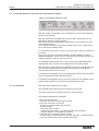
DP-WIN (Version 3.1)
Test and demonstration
software for PROFIBUS DP
actuators
Manual
AUMA DP-WIN Version 3.1
AUMA MATIC/ AUMA VARIOMATIC PROFIBUS DP
Scope of these instructions:
Manual
These instructions are valid for AUMA actuators with controls AUMA
MATIC/ AUMA VARIOMATIC PROFIBUS DP.
Table of Contents
1. Introduction. . . . . . . . . . . . . . . . . . . . . . . . . . . . . . . . . . . . . . . . . . . . . . . . . 3
1.1 Summary of functions . . . . . . . . . . . . . . . . . . . . . . . . . . . . . . . . . . . . . . . . . . . 3
2. Installation . . . . . . . . . . . . . . . . . . . . . . . . . . . . . . . . . . . .
2.1 Hardware and software requirements. . . . . . . . . . . . . . . . . . . . . .
2.1.1 Hardware . . . . . . . . . . . . . . . . . . . . . . . . . . . . . . . . . . . .
2.1.2 Software. . . . . . . . . . . . . . . . . . . . . . . . . . . . . . . . . . . . .
2.2 Installation. . . . . . . . . . . . . . . . . . . . . . . . . . . . . . . . . . . .
2.2.1 Installation of the Master card and the Profibus Application Program Interface
2.2.2 Installation of the program DP-WIN . . . . . . . . . . . . . . . . . . . . . . .
2.2.3 Starting the program . . . . . . . . . . . . . . . . . . . . . . . . . . . . . .
.
.
.
.
.
.
.
.
.
.
.
.
.
.
.
.
.
.
.
.
.
.
.
.
.
.
.
.
.
.
.
.
.
.
.
.
.
.
.
.
.
.
.
.
.
.
.
.
.
.
.
.
.
.
.
.
.
.
.
.
.
.
.
.
.
.
.
.
.
.
.
.
.
.
.
.
.
.
.
.
.
.
.
.
.
.
.
.
.
.
.
.
.
.
.
.
.
.
.
.
.
.
.
.
3
3
3
3
3
3
4
4
3. User interface. . . . . . . . . . . . . . . . . . . . . . . . . .
3.1 The menu bar . . . . . . . . . . . . . . . . . . . . . . . . .
3.1.1 File . . . . . . . . . . . . . . . . . . . . . . . . . . . . . .
3.1.2 Bus parameters . . . . . . . . . . . . . . . . . . . . . . . .
3.1.3 Master-Mode . . . . . . . . . . . . . . . . . . . . . . . . .
3.1.4 Tests . . . . . . . . . . . . . . . . . . . . . . . . . . . . .
3.1.5 Options . . . . . . . . . . . . . . . . . . . . . . . . . . . .
3.1.6 DPV1 . . . . . . . . . . . . . . . . . . . . . . . . . . . . .
3.1.7 The menu item ”?” . . . . . . . . . . . . . . . . . . . . . .
3.2 The tool bar . . . . . . . . . . . . . . . . . . . . . . . . . .
3.2.1 Info . . . . . . . . . . . . . . . . . . . . . . . . . . . . . .
3.2.2 Master Stop . . . . . . . . . . . . . . . . . . . . . . . . . .
3.2.3 Master Clear . . . . . . . . . . . . . . . . . . . . . . . . .
3.2.4 Master Operate . . . . . . . . . . . . . . . . . . . . . . . .
3.2.5 Save parameters . . . . . . . . . . . . . . . . . . . . . . .
3.2.6 Load parameters . . . . . . . . . . . . . . . . . . . . . . .
3.2.7 Operating test . . . . . . . . . . . . . . . . . . . . . . . . .
3.2.8 Torque monitoring. . . . . . . . . . . . . . . . . . . . . . .
3.3 The window Profibus stations (live list) . . . . . . . . . . . .
3.4 The window Actuator status (process representation input) .
3.5 The window Actuator control (process representation output)
3.6 The status bar. . . . . . . . . . . . . . . . . . . . . . . . .
.
.
.
.
.
.
.
.
.
.
.
.
.
.
.
.
.
.
.
.
.
.
.
.
.
.
.
.
.
.
.
.
.
.
.
.
.
.
.
.
.
.
.
.
.
.
.
.
.
.
.
.
.
.
.
.
.
.
.
.
.
.
.
.
.
.
.
.
.
.
.
.
.
.
.
.
.
.
.
.
.
.
.
.
.
.
.
.
.
.
.
.
.
.
.
.
.
.
.
.
.
.
.
.
.
.
.
.
.
.
.
.
.
.
.
.
.
.
.
.
.
.
.
.
.
.
.
.
.
.
.
.
.
.
.
.
.
.
.
.
.
.
.
.
.
.
.
.
.
.
.
.
.
.
.
.
.
.
.
.
.
.
.
.
.
.
.
.
.
.
.
.
.
.
.
.
.
.
.
.
.
.
.
.
.
.
.
.
.
.
.
.
.
.
.
.
.
.
.
.
.
.
.
.
.
.
.
.
.
.
.
.
.
.
.
.
.
.
.
.
.
.
.
.
.
.
.
.
.
.
.
.
.
.
.
.
.
.
.
.
.
.
.
.
.
.
.
.
.
.
.
.
.
.
.
.
.
.
.
.
.
.
.
.
.
.
.
.
.
.
.
.
.
.
.
.
.
.
.
.
.
.
.
.
.
.
5
5
5
5
5
5
6
6
6
6
6
6
6
6
6
6
7
7
7
8
9
9
.
.
.
.
.
.
.
.
.
.
.
.
.
.
.
.
.
.
.
.
.
.
.
.
.
.
.
.
.
.
.
.
.
.
.
.
.
.
.
.
.
.
.
.
.
.
.
.
.
.
.
.
.
.
.
.
.
.
.
.
.
.
.
.
.
.
.
.
.
.
.
.
.
.
.
.
.
.
.
.
.
.
.
.
.
.
.
.
.
.
.
.
.
.
.
.
.
.
.
.
.
.
.
.
.
.
.
.
.
.
.
.
.
.
.
.
.
.
.
.
.
.
.
.
.
.
.
.
.
.
.
.
.
.
.
.
.
.
.
.
.
.
.
.
.
.
.
.
.
.
.
.
.
.
.
.
.
.
.
.
.
.
.
.
.
.
.
.
.
.
.
.
.
.
.
.
.
.
.
.
.
.
.
.
.
.
.
.
.
.
.
.
.
.
.
.
.
.
4. Operating test . . . . . . . . . . . . . . . . . . . . . . . . . . . . . . . . . . . . . . . . . . . . . . . 10
5. Trouble shooting and corrective actions . . . . . . . . . . . . . . . . . . . . . . . . . . . . . . . . 11
2
AUMA DP-WIN Version 3.1
AUMA MATIC/ AUMA VARIOMATIC PROFIBUS DP
Manual
1.
Introduction
1.1 Summary of functions
2.
DP-WIN is the Profibus DP test- and demonstration software for AUMA
actuators.
AUMA actuators with Profibus DP interface can be tested on site with this
program. It can also be used as a demonstration software to show the
characteristics of the AUMA Profibus DP actuators.
..
..
..
.
Display of all stations on the Profibus (live list).
All information supplied by the actuator via Profibus DP is displayed.
Control of AUMA actuators.
Automatic operating test for AUMA actuators.
The AUMA parameters can be set.
Parameter sets can be saved.
Read-out of operational data and electronic name plate (if available in
actuator, software version in actuator: Z027.988A).
Installation
..
..
..
2.1 Hardware and software requirements
2.1.1 Hardware
2.1.2 Software
2.2 Installation
PC or PC compatible laptop (Pentium class or higher)
min. 32 MB RAM.
min. 5 MB memory on hard drive
Softing PROFIcard (PCMCIA) or Softing PROFIBoard (ISA) Profibus
Master card
Operating system Windows 95, 98, NT 4.0, or Windows 2000
Softing Windows NT PROFIBUS Application Program Interface Version
5.24 (included on the CD)
Installation is done in two steps.
2.2.1 Installation of the Master card and the Profibus Application Program Interface
Please perform the installation according to the instructions of the
”PROFIcard Installation and Hardware User Manual” and the ”PROFI
BOARD User Manual”.
.
.
To be able to install the ”Profibus Application Program
Interface” the user must be logged in with the
administrator password.
The automatic setting of the interrupt does not always
function when the Proficard is installed under
Windows NT.
We recommend to individually select a free interrupt.
After correct installation of the card the following program symbol should
appear in the system control:
3
AUMA DP-WIN Version 3.1
AUMA MATIC/ AUMA VARIOMATIC PROFIBUS DP
Manual
After a double-click on the symbol, the following window should open
(Node0 checked):
Figure 1: PROFIBUS Control Panel, example: Toshiba CDT4010 CDT laptop
If a red cross instead of a green check mark is displayed, the settings of
either the IO Port, the DP RAM address or the interrupt are not correct. In
this case, please check the free resources of the computer with the program
Windows NT diagnosis which can be started via ”Start -> Programs ->
Administration (general)”.
2.2.2 Installation of the program DP-WIN
Insert the CD labelled DP-WIN Version 3.0 into the CD-ROM drive of the
computer and start the program:
Afterwards please follow the instructions of the program
2.2.3 Starting the program
After installation, start the program DP-WIN by double-clicking on
under ”Start -> Programs”.
4
AUMA DP-WIN Version 3.0
AUMA MATIC/ AUMA VARIOMATIC PROFIBUS DP
Handbuch
3.
User interface
3.1 The menu bar
3.1.1 File
3.1.2 Bus parameters
Figure 2: The user interface of DP-WIN
..
.
.
The menu bar offers the following options:
.
.
3.1.3 Master-Mode
3.1.4 Tests
.
.
.
.
.
German: Selects the German texts for indication.
English: Selects the English texts for indication.
After having changed the language, DP-WIN must be re-started.
Exit:
Closes the program.
Master-Bus parameters:
The other menu points can only be selected if the check box ”Send GSD
parameters” in this window is activated.
No GSD parameters are sent automatically to the actuator upon starting
DP-Win Version 3.0.
This prevents the possible overwriting of a programming that was done
via the acyclic services (e.g. with the PDM program).
Parameter save:
All parameters set under the menu Bus parameters are saved.
Parameter load:
The parameters are loaded and activated.
With this menu it is possible to change the operation mode of the master.
The following operation modes are possible:
Stop: Master does only process level 2. Live list still works. Process
representation is not transmitted.
Clear: Master reads process representation input, but does not control
actuator.
Operate: Master reads process representation input and controls
actuator. (normal operation mode)
Operating test: Automatically conducts an operating test. Detailed
description see clause 4.
Torque measurement: For actuators with the option ”Analogue torque
value transmitted via Profibus” the torque can be monitored for the travel.
5
AUMA DP-WIN Version 3.1
AUMA MATIC/ AUMA VARIOMATIC PROFIBUS DP
Manual
3.1.5 Options
Function second analogue input:
In this menu it is determined whether the second analogue input is used for
measuring the torque (for actuators type AS) or as an external sensor.
3.1.6 DPV1
In this menu, acyclic communication services can be executed. They work
together with the Software Z027.988A.
..
.
.
..
Read/ write: grants access to different slots and indexes.
Electronic name plate: grants access to the electronic name plate stored
in the actuator
Operating data: grants access to the operating data stored in the
actuator
AUMA special: grants access to some of the internal memory cells of the
actuator
GSD data: grants access to the GSD data stored in the actuator
Database: for saving and loading of acyclic data. Requires an additional
component.
3.1.7 The menu item ”?”
Information on the program DP-Win can be found here.
3.2 The tool bar
Figure 3: Tool bar
Load parameters
Save parameters
Info
Torque monitoring
Operating test
Master Stop
Master Operate
Master Clear
3.2.1 Info
Here a short information about the DP-WIN program and the current version
is displayed.
3.2.2 Master Stop
Puts the master in STOP-state.
In STOP-state, there is no communication between master and actuator, i.e.
the master can neither control the actuator nor read data from the actuator.
3.2.3 Master Clear
Puts the master in CLEAR-state.
In CLEAR-state, the master only reads the data from the slave. But it can no
longer control the slave. In this state, the actuator will perform a safety
operation when it has been programmed accordingly.
3.2.4 Master Operate
Puts the master in OPERATE-state. It can then control the actuator again.
3.2.5 Save parameters
All parameters set under the menu Bus parameters are saved.
3.2.6 Load parameters
The parameters are loaded and activated.
6
AUMA DP-WIN Version 3.1
AUMA MATIC/ AUMA VARIOMATIC PROFIBUS DP
Manual
3.2.7 Operating test
Clicking this button opens the window Operating test.
Functionality of the actuator can be checked with the operating test. The
operating test is described in detail in chapter 4.
3.2.8 Torque monitoring
For actuators with the option ”Analogue torque value transmitted via
Profibus” this tool makes it possibleto monitor the torque for the travel.
3.3 The window Profibus stations (live list)
Figure 4: The window Profibus stations (live list)
This window shows the addresses of all stations connected to the Profibus.
Furthermore, it is indicated whether the station is a master (control, e. g.
PLC or PC) or a slave (e. g. AUMA actuator).
Clicking a slave number will mark it. The program then controls the marked
slave.
The main live list shows the total of all stations (including the master) of the
bus. With this overview it is easy to check which stations are available
within the bus.
If no slave is selected by the user after switching on, the slave with the
smallest address will automatically be selected after 7 seconds.
If no stations are shown in the live list this may point to a short-circuit in the
Profibus.
The program should then be started again without connection to the bus.
If the master is now shown as the only station, either the Profibus has a
short-circuit or the bus termination is faulty (no voltage at bus termination).
7
AUMA DP-WIN Version 3.1
AUMA MATIC/ AUMA VARIOMATIC PROFIBUS DP
Manual
3.4 The window Actuator status (process representation input)
This window displays the actuator’s status sent by the actuator to the
master.
If communication fails this window is not opened.
Figure 5: The window Actuator status (Process representation input)
..
..
The individual Bits in the process representation input are shown in different
colours.
light green: the Bit is not active (0)
dark green: the Bit is active (1)
red: the Bit is active (1). A fault or warning has occurred.
light gray: with the present configuration the Bit is not transmitted.
In the field ”Input Bytes hex.” the individual input bytes are shown as
hexadecimal figures.
The analogue values from the positioner and from the customer’s analogue
inputs are shown as decimal values and graphically as bars or sliding
scales.
Setting for the code of measurement values (percent or per mil) of the
AUMA parameters is automatically accounted for when displaying bars or
sliding scales.
The meaning of the individual information is explained in the operation
instructions for Profibus-DP actuators.
8
AUMA DP-WIN Version 3.1
AUMA MATIC/ AUMA VARIOMATIC PROFIBUS DP
Manual
3.5 The window Actuator control (process representation output)
Figure 6: The window ”Actuator control”
With this window, the actuator can be controlled. If communication fails this
window is not opened.
With the buttons remote OPEN and remote CLOSE, the actuator can be
operated in opening or closing direction.
With 'Set point' the modulating duty is switched on. The actuator now runs
to the defined position.
The set point can either be set with the sliding scale or as a number in the
box to the left of the sliding scale.
If a command is active this is shown by a check mark in the box to the left of
the button.
Only one of the three commands REMOTE OPEN, REMOTE CLOSE or
REMOTE NOMINAL can be active. If more than one command is active, the
actuator signals the fault ”incorrect command”.
For adjustable speed actuators (e.g. AS or SARV with VARIOMATIC) the
output speed of the actuator can be determined by the speed setting .
With the button ”trigger fail safe” the fail safe function can be triggered in the
ALS actuator equipped with mechanical fail safe function. With all other
actuators this button has no function.
In actuators pre-equipped for this, the tripping device for the PTC thermistor
can be reset with the button TMS Reset (PTC).
In actuators pre-equipped for this, the local controls can be released via the
Profibus with the button Local Control Unit (Vandalism security).
3.6 The status bar
The status bar is divided into four fields.
The first field shows help texts for the buttons in the tool bar.
The second field shows the status of the bus communication.
.
.
The following indications are possible:
.
Bus communication OK
No fault in the communication has occurred
Fault: No connection to the slave
There is no communication with the slave.
Possible causes:
- Bus cable open circuited.
- Faults on the bus cable, e. g. due to incorrect bus termination.
- Supply voltage is not available for the slave
Fault: Slave is occupied by another master
Another master communicates in cycles with the slave. The other master
has to be switched off in order to elimitate this fault.
9
AUMA DP-WIN Version 3.1
AUMA MATIC/ AUMA VARIOMATIC PROFIBUS DP
.
.
.
Manual
Fault: Faulty parameters
The parameters under the menu items
Bus parameters: Slave AUMA parameters / Slave Profibus parameters
are set incorrectly or contradictory.
Fault: Incorrect configuration
The configuration set under the menu item Bus parameters: slave
configuration is not allowed (the version K10000x.DX.000 does not allow
all configurations).
Error: no AUMA slave, Ident No. xxxx.
The selected slave is not an AUMA slave.
The DP-WIN program version 3.0 can only control and show the status of
AUMA slaves with the ident no. 0732 hex.
The third field shows the number of connection faults. This may be useful
for long-time tests and fault finding.
..
.
The fourth field shows the status of the master:
If the master is in STOP-state, it does not communicate with the slave.
If the master is in CLEAR-state, the actuator cannot be controlled, but the
feedback of the actuator is read.
If the master is in OPERATE-state, it is totally operative.
4.
Operating test
Correct operation of the actuator can be checked with the operating test.
The button Operating test can only be clicked if the communication to the
selected actuator is active.
On clicking the button Operating test, the following dialogue appears:
Figure 7: The dialogue operating test
The operating test is started after the button Start/Stop has been clicked. It
can be stopped by pressing the button Start/Stop again.
When starting the operating test the actuator first runs to completely closed.
The actuator then runs in direction OPEN until the end position CLOSED is
exited. If after 10 seconds the end position has not been exited, the
operating test will be stopped with a fault signal.
The actuator will then be operated from CLOSED to OPEN. In addition, the
operating time is determined.
Similar to the end position CLOSED, functionality of the signalisation of the
end positions (normally the microswitches) is tested for the end position
OPEN.
The actuator will then run to its original position.
After the operating test was performed without fault, the indication
‘operating test successful’ will be shown. If a fault occurs, the operating test
is interrupted and the cause of the fault is shown.
The field Operating time shows the operating time which was determined
during the last operating test.
10
AUMA DP-WIN Version 3.1
AUMA MATIC/ AUMA VARIOMATIC PROFIBUS DP
Manual
If the box 'Repeating operating test cyclic' is selected, the actuator will on
completion of the test not run to the original position. Instead the operating
test will be repeated.
With the box ‘pause time between two operating tests in sec’ the time
between the end of a operating test cycle and the start of the next cycle can
be set.
5.
Trouble shooting and corrective actions
When the program is started the following message can appear:
Figure 8: Start fault
.
Then the check the following points:
.
Has the program DP-Win been started twice simultaneously?
If yes,
- exit the DP-WIN program,
- end the process dp_win.exe in the task manager
- start DP-WIN again
or restart your computer.
Is there a fault in the Profibus cable?
- Pull out the Profibus plug from the master,
- exit the DP-WIN program,
- end the process dp_win.exe in the task manager
- start DP-WIN again
or restart your computer.
If the error message has now disappeard and the green LED on the
Profibus Master card is illuminated, a fault has occurred (e.g. a short-circuit
or no power at the termination resistances).
.
Does the driver work:
- Start the computer again without starting DP-WIN.
- After correct installation of the card the following program symbol should
appear in the system control:
After a double-click on the symbol, the following window should open
(Node0 checked):
11
AUMA DP-WIN Version 3.1
AUMA MATIC/ AUMA VARIOMATIC PROFIBUS DP
Manual
Figure 9: PROFIBUS Control Panel when ProfiCard was incorrectly installed
Program DP-WIN must not be running!
If a red cross instead of a green check mark is displayed, the settings of the
IO Port, the DP RAM address or the interrupt are probably not correct. In
this case, please check the free resources of the computer with the program
Windows NT diagnosis which can be started via ”Start -> Programs ->
Administration (general)” and change the settings of the ProfiCard with the
button ”Edit”. For this you must be logged in as administrator.
12
Manual
AUMA DP-WIN Version 3.1
AUMA MATIC/ AUMA VARIOMATIC PROFIBUS DP
13
AUMA DP-WIN Version 3.1
AUMA MATIC/ AUMA VARIOMATIC PROFIBUS DP
Manual
Index
A
Actuator status
Addresses
Analogue input
AUMA special
8
7
6
6
B
Bus parameters
5
C
Clear
5
D
Database
6
E
Electronic name plate
6
F
Functions
3
14
G
GSD data
6
H
Hardware
3
I
Info
Installation
Introduction
6
3
3
L
Load parameters
6
M
Master-Bus parameters
Master Clear
Master-Mode
Master Operate
Master Stop
5
6
5
6
6
O
Operate
Operating data
Operating test
5
6
7,10
R
Read/write
6
S
Save parameters
Software
Status bar
Stop
6
3
9
5
T
Tool bar
Torque monitoring
Trouble shooting
6
5,7
11
AUMA DP-WIN Version 3.1
AUMA MATIC/ AUMA VARIOMATIC PROFIBUS DP
Manual
Deutschland / Germany
DE
DE
DE
Werner Riester GmbH & Co. KG
Werk Müllheim
Postfach 1362
79373 Müllheim
Tel
+49 7631 809 0
Fax
+49 7631 809 250
E-Mail [email protected]
Werner Riester GmbH & Co. KG
Werk Ostfildern-Nellingen
Postfach 1151
73747 Ostfildern
Tel
+49 7113 4803 - 0
Fax
+49 7113 4803 - 34
E-Mail [email protected]
Werner Riester GmbH & Co. KG
Service-Center Magdeburg
Am Stadtberg 1
39167 Niederndodeleben
Tel
+49 39204 759 - 0
Fax
+49 39204 759 - 19
E-Mail [email protected]
DE
Werner Riester GmbH & Co. KG
Service-Center Köln
Toyota-Allee 44
50858 Köln
Tel
+49 2234 20379 - 00
Fax
+49 2234 20379 - 99
E-Mail [email protected]
DE
Werner Riester GmbH & Co. KG
Service-Center Bayern
Robert-Bosch-Strasse 14
85748 Garching-Hochbrück
Tel
+49 89 329885 - 0
Fax
+49 89 329885 - 18
E-Mail [email protected]
DE
Werner Riester GmbH & Co. KG
Büro Nord, Bereich Schiffbau
Tempowerkring 1
21079 Hamburg
Tel
+49 40 791 40285
Fax
+49 40 791 40286
E-Mail [email protected]
DE
Werner Riester GmbH & Co. KG
Büro Nord, Bereich Industrie
Krelingen 150
29664 Walsrode
Tel
+49 5167 504
Fax
+49 5167 565
E-Mail [email protected]
DE
Werner Riester GmbH & Co. KG
Büro Ost
Am Stadtberg 1
39167 Niederndodeleben
Tel
+49 39204 75980
Fax
+49 39204 75989
E-Mail [email protected]
DE
DE
DE
DE
Werner Riester GmbH & Co. KG
Büro West
Rathausplatz 7
45549 Sprockhövel
Tel
+49 2339 9212 - 0
Fax
+49 2339 9212 - 15
E-Mail [email protected]
Werner Riester GmbH & Co. KG
Büro Süd-West
Mozartstraße 4
69488 Birkenau
Tel
+49 6201 373149
Fax
+49 6201 373150
E-Mail [email protected]
Werner Riester GmbH & Co. KG
Büro Württemberg
Postfach 1151
73747 Ostfildern
Tel
+49 711 34803 80
Fax
+49 711 34803 81
E-Mail [email protected]
Werner Riester GmbH & Co. KG
Büro Baden
Postfach 1362
79373 Müllheim
Tel
+49 7631 809-193
Fax
+49 7631 809-294
E-Mail [email protected]
DE
Werner Riester GmbH & Co. KG
Büro Kraftwerke
Postfach 1362
79373 Müllheim
Tel
+49 7631 809 - 192
Fax
+49 7631 809 - 294
E-Mail [email protected]
DE
Werner Riester GmbH & Co. KG
Büro Bayern
Kagerberg 12
93356 Teugn/Niederbayern
Tel
+49 9405 9410 24
Fax
+49 9405 9410 25
E-Mail [email protected]
Europa / Europe
AT
CH
CZ
FI
FR
GB
IT
NL
PL
RU
DK
ES
GR
NO
PT
AUMA Armaturenantriebe GmbH
Handelsstraße 14
2512 Tribuswinkel
Tel
+43 2252 82540
Fax
+43 2252 8254050
E-Mail [email protected]
AUMA (Schweiz) AG
Chörrenmattstrasse 43
8965 Berlikon
Tel
+41 566 400945
Fax
+41 566 400948
E-Mail [email protected]
SE
TR
AUMA Servopohony spol. s.r.o.
Kazanská 121
10200 Praha 10
Tel
+420 272 700056
Fax
+420 272 704125
E-Mail [email protected]
US
OY AUMATOR AB
PI 21 / Hyljekuja 5
02271 Espoo 27
Tel
+35 895 84022
Fax
+35 895 8402300
E-Mail [email protected]
CA
AUMA ITALIANA S.r.l.
Via Don Luigi Sturzo, 29
20020 Lainate Milano
Tel
+39 0 2 9317911
Fax
+39 0 2 9374387
E-Mail [email protected]
AUMA BENELUX B.V.
Le Pooleweg 9
2314 XT Leiden
Tel
+31 71 581 40 40
Fax
+31 71 581 40 49
E-Mail [email protected]
AUMA Polska Sp. zo. o.
UI. Pukowca
40-816 Katowice
Tel
+48 32 2509518
Fax
+48 32 2505412
E-Mail [email protected]
AUMA Priwody OOO
12, 3-y Pavlovsky Pereulok
113093 Moscow
Tel
+7 095 236 55 04
Fax
+7 095 236 55 04
E-Mail [email protected]
GRØNBECH & SØNNER A/S
Scandiagade 25
2450 Copenhagen SV
Tel
+45 3326 6300
Fax
+45 3326 6301
E-Mail [email protected]
IBEROPLAN S.A.
Marques de Hoyos, 10
28027 Madrid
Tel
+34 91 3717130
Fax
+34 91 7427126
E-Mail [email protected]
D. G. Bellos & Co. O.E.
86, Konstantinoupoleos St.
13671 Acharnai Athens
Tel
+30 10 2409485
Fax
+30 10 2409486
E-Mail [email protected]
SIGURD SØRUM A. S.
Postboks 85
Jongsasveien 3
1301 Sandvika
Tel
+47 67572600
Fax
+47 67572610
E-Mail [email protected]
INDUSTRA
5° Centro Empresarial Sintra-Estoril
Bloco A3, Estrada de Albarraque Linhó
2710-297 Sintra
Tel
+351 2 1910 95 00
Fax
+351 2 1910 95 99
E-Mail [email protected]
MEGA Endüstri Kontrol Sistemieri
Tic. Ltd. Sti.
Cetin Emec Bulvari 6.CAD 78.SK.
17/18
06460 Övecler Ankara
Tel
+90 312 4780813
Fax
+90 312 4780831
E-Mail [email protected]
Asien / Asia
IN
JP
Nordamerika / North America
AUMA France
Z.A.C. Les Châtaigniers III
95157 Taverny Cédex
Tel
+33 1 39327272
Fax
+33 1 39321755
E-Mail [email protected]
AUMA ACTUATORS Ltd.
Britannia Way
Clevedon North Somerset BS21 6QH
Tel
+44 1275 871141
Fax
+44 1275 875492
E-Mail [email protected]
ERICHS ARMATUR AB
Box 9144
Travbanegatan 8
20039 Malmö
Tel
+46 40 311550
Fax
+46 40 945515
E-Mail [email protected]
MX
AUMA ACTUATORS INC.
4 Zesta Drive
PA 15 205 Pittsburgh
Tel
+1 412 7871340
Fax
+1 412 7871223
E-Mail [email protected]
TROY-ONTOR Inc.
230 Bayview Drive, Unit 1 A
L4N 5E9 Barrie Ontario
Tel
+1 705 721-8246
Fax
+1 705 721-5851
E-Mail [email protected]
IESS DE MEXICO S. A. de C. V.
Av. cuitlahuac 1422, Col. Aguilera,
Delegacion Atzco.
C.P. 02900 Mexico D.F.
Tel
+52 555 61 701
Fax
+52 535 63 337
E-Mail [email protected]
SG
AE
CN
Südamerika / South America
CL
AR
BR
CO
PE
PR
VE
AUMA Chile Respresentative
Office
Avenida Larrin 6642, Of. 304
La Reina Santiago de Chile
Tel
+56 22 77 71 51
Fax
+56 22 77 84 78
E-Mail [email protected]
HK
LOOP S. A.
Chacabuco 580
1069 Buenos Aires
Tel
+54 11 43 31 32 06
Fax
+54 11 43 31 32 06
E-Mail [email protected]
Asvotec Termoindustrial Ltda.
Rod. Cônego Cyriaco S. Pires, km 01
13190-000 Monte Mor/ SP.
Tel
+55 19 3879 8735
Fax
+55 19 3879 8738
E-Mail [email protected]
Ferrostaal de Colombia Ltda.
Apartado Aereo 7384
Avenida Eldorado No. 97-03
Bogotá D.C.
Tel
+57 1 4 011 300
Fax
+57 1 4 131 806
E-Mail
[email protected]
KR
KW
Suplibarca
Centro Comercial Carmen, Avenia La
Limpia Local 1-2 # 85-39
Maracaibo Edo, Zulia
Tel
+58 261 7 555 667
Fax
+58 261 7 532 259
E-Mail [email protected]
ZA
EG
AUMA ACTUATORS (Singapore)
Pte Ltd.
32, Ang Mo Kio Industrial Park 2 #01
- 02, Sing Industrial Complex
569510 Singapore
Tel
+65 6 4818750
Fax
+65 6 4818269
E-Mail [email protected]
AUMA Middle East Representative
Office
P.O. Box 26675
Sharjah
Tel
+971 6 5746250
Fax
+971 6 5746251
E-Mail [email protected]
AUMA Beijing Representative
Office
Room 602, Yuanchenxin Building, 12
Yumin Road, Madian Chaoyang
District
100029 Beijing
Tel
+86 10 62022491
Fax
+86 10 62022497
E-Mail [email protected]
PERFECT CONTROLS Ltd.
Suite 202, Block 1, Hofai Commercial
Centre 218 Sai Lau Kok Road
Tsuen Wan, Kowloon
Tel
+852 24163726
Fax
+852 24163763
E-Mail [email protected]
DONG WOO Valve Control Co.,
Ltd.
P.O. Box 4
24-2, Youi Do-Dong, Yeong Deung
Po-Ku
150-010 Seoul Korea
Tel
+82 27 61 62 33
Fax
+82 27 61 12 78
E-Mail [email protected]
AL-ARFAJ Eng. Company W. L. L.
P.O. Box 391
22004 Salmiyah
Tel
+965 4817448
Fax
+965 4817442
E-Mail [email protected]
QA
TH
Sunny Valves and Intertrade Corp.
Ltd.
232/13 Yen-A-Kart Soi 2
10120 Yannawa Bangkok
Tel
+66 2 2401656
Fax
+66 2 2401095
E-Mail [email protected]
TW
Top Advance Enterprises Ltd.
2nd Fl., No. 32, Lane 308, Section 3,
Ho-Ping East Road
Taipei
Tel
+886 2 27333530
Fax
+886 2 27365526
E-Mail [email protected]
Australien / Australia
Afrika / Africa
AUMA South Africa (Pty) Ltd.
P.O. Box 1283
1560 Springs
Tel
+27 11 3632880
Fax
+27 11 8185248
E-Mail [email protected]
AUMA JAPAN Co., Ltd.
596-4 Futago-Cho
273-0034 Funabashi Chiba
Tel
+81 47 3029551
Fax
+81 47 3029555
E-Mail [email protected]
BEHZAD Trading
P.O. Box 1123
Rayyan Road
Doha
Tel
+974 4433 236
Fax
+974 4433 237
E-Mail [email protected]
Multi-Valve Latin America S. A.
Amador Merino Reyna 496, OF 301
San Isidro Lima 27
Tel
+511 222 1313
Fax
+511 222 1880
E-Mail [email protected]
PASSCO Inc.
P.O. Box 36 41 53
00936-4153 San Juan
Tel
+18 09 78 77 20 87 85
Fax
+18 09 78 77 31 72 77
E-Mail [email protected]
AUMA (India) Ltd.
Plot No. 39-B, II Phase Peenya
Industrial Area
560 058 Bangalore
Tel
+91 80 8394655
Fax
+91 80 8392809
E-Mail [email protected]
AU
BARRON GJM Pty. Ltd.
P.O. Box 792
78 Dickson Avenue
NSW 1570 Artarmon
Tel
+61 294361088
Fax
+61 294393413
E-Mail [email protected]
A.T.E.C.
5, Road No. 101 Maadi
Cairo
Tel
+20 2 35899680
Fax
+20 2 3586621
E-Mail [email protected]
15
Multi-turn actuators
SA 07.1 – SA 16.1 / SA 25.1 – SA 48.1
Torques from 10 to 32 000 Nm
Output speeds from 4 to 180 min-1
Multi-turn actuators SA/ SAR
with controls AUMATIC
Torques from 10 to 1 000 Nm
Speeds from 4 to 180 min-1
Part-turn actuators
SG 05.1 – SG 12.1
Torques from 100 to 1 200 Nm
Operating times for 90° from 4 to 180 s
Multi-turn actuators SA/ SAR
with linear thrust units LE
Thrusts from 4 kN to 217 kN
Strokes up to 500 mm
Linear speeds
from 20 to 360 mm/min
Part-turn actuators
AS 6 – AS 50
Torques from 25 to 500 Nm
Operating times for 90° from 4 to 90 s
Bevel gearboxes
GK 10.2 – GK 40.2
Torques up to 16 000 Nm
Spur gearboxes
GST 10.1 – GST 40.1
Torques up to 16 000 Nm
Worm gearboxes with base and lever
GF 50.3 – GF 125.3
GF 160 – GF 250
Torques up to 32 000 Nm
WERNER RIESTER GmbH & Co. KG
Armaturen- und Maschinenantriebe
Postfach 1362
D - 79373 Müllheim
Tel 07631/809-0 Fax 07631/809-250
e-mail [email protected]
http://www.auma.com
Worm gearboxes
GS 40.3 – GS 125.3
GS 315 – GS 500
Torques up to 360 000 Nm
WERNER RIESTER GmbH & Co. KG
Armaturen- und Maschinenantriebe
P.O. Box 1151 D - 73747 Ostfildern
Tel +49 711/34803-0
Fax +49 711/34803-34
Y001.328/003/en/1.02