1
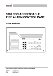
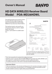
English Français Deutsch Nederlands Svenska 997-493-001, Issue 1.0 November 2003 Islenska EN54 2- 8 Zone Conventional Fire Control Panel User Manual English Panel Functions & Indicators - Key to Icons General & Zone Fire LEDs ACCEPT SOUNDERS START/ STOP RESET BUZZER MUTE KEYSWITCH DELAY ON/OFF ITEM SELECT Zone FAULT/ DISABLE/ TEST LEDs System LEDs LAMP TEST DISABLE/ TEST/ NORMAL Contents 1 Introduction ................................................................. 1 2 Panel Indicators & Controls ......................................... 1 2.1 Indicators ....................................................................... 1 2.2 Controls ......................................................................... 2 3 4 5 6 FIRE - What do you do? .............................................. Sounders - How to Stop/Start ...................................... FAULT - What do you do? ........................................... TEST /DISABLEMENT Functions (Access Level 2) ....... 3 3 4 4 6.1 Lamp Test ...................................................................... 4 6.2 Test/ Disable Options .................................................... 5 6.3 Delay On/Off .................................................................. 6 7 Maintenance ................................................................ 6 EN54 2-8 Zone Conventional Fire Panel - User Manual Introduction Only authorised and suitably-trained personnel must carry out procedures in response to fire alarm events or perform scheduled test and maintenance activities. This manual contains operating instructions for the EN54, 2 - 8 zone conventional fire control panel. All the control and operation functions described in this manual can be carried out using the pushbuttons on the front of the panel. Users of this manual are assumed to be working with a panel that has already been installed and configured appropriately for the area under its supervision. 2 Panel Indicators and Controls The panels indicators display the panel status and the controls are used to operate the overall system. The panel has up to eight zonal LED indicators, a FIRE indicator, thirteen system status LED indicators and eight function pushbuttons. 2.1 Indicators The location of the panels indicators is shown below: FIRE - The following red status indicators are provided: General Fire and 8 Zone Fire LEDs FAULT - The following yellow status indicators are provided: Fault /Disabled /Test and 8 Zone Fault /Disable /Test LEDs SYSTEM - The following 13 status LEDs are provided: Power available - mains and/or battery ................................................... G General Fault; General Disablement; General Test; Delay On (active); System Fault; Earth Fault; Power Supply Fault; Sounder Fault /Disabled; Fire Routing Fault /Disabled; Fault Routing Fault /Disabled; Auxiliary Fault ........................ Y Fire Brigade Called /Fire Routing Output Active ...................................... R Note: Yellow LEDs: Red LEDs: Flashing - Fault; Steady - Disablement. Flashing - New alarm; Steady - Accepted alarm. 1 997-493-001, Issue 1 English 1 EN54 2-8 Zone Conventional Fire Panel - User Manual English Buzzer This activates with panel status change, i.e. through FIRE or FAULT condition. When active the buzzer indicates the highest priority condition, e.g. FIRE over FAULT. Push-button operation is confirmed by a brief audible buzzer action. 2.2 Controls The position of the panels controls and keyswitch is shown below: The access Level of the panels controls is indicated. 1, 2 1, 2 2 2 1 1 2 2 1, 2 Keyswitch A keyswitch provides access to the Level 2 control functions. Insert the key and turn clockwise through 90°. Access Level 1 and 2 control functions are described below. Other Controls: ..... Access Level 2 - changes any flashing indications of new zones in fire to steady indications of confirmed zones in fire, mutes the buzzer and extends any delay. ..... Access Level 1 - changes (mutes) operation of internal buzzer; changes flashing indications of new zones in fire to steady indications of confirmed zones in fire. ..... Access Level 1 - ends an active delay and activates any configured outputs. ..... Access Level 2 - with no delays active - toggles the delay mode. ..... Access Level 2 - with panel in a quiescent state - activates all sounders for EVACUATE . ..... Access Level 2 - returns panel to its normal quiescent condition; test and disablement modes are not affected and remain active after this selection. Existing fire conditions are re-indicated within 3 secs and/or any fault conditions within 100 secs. ..... Access Level 2 - used with to select disablement and test mode selections. See Section 6 TEST/DISABLEMENT Functions. ..... Access Level 2 - used with to cycle though normal, disablement or test states of selections. See Section 6 TEST/DISABLEMENT Functions. ..... Access Level 2 - illuminates all LEDs and operates internal buzzer. 997-493-001, Issue 1 2 EN54 2-8 Zone Conventional Fire Panel - User Manual FIRE - Red LED Indication - What do you do? No delays configured: Status: English 3 - Flashing - Steady tone - Operating Action/Result: Press to silence the buzzer and change LED to steady. With configured delay: Status: - Flashing - Flashing:1st stage - Steady tone Action/Result: L1 - Press to silence the buzzer and change the LED to steady - the LED flashes; press to end delay. L2 - Press to extend delay. 4 Sounders - How to Stop/Start To stop/start sounders: Status: - Flashing - Operating - Steady tone Action/Result and turn 1 Insert key 90° clockwise. 2 Press . Sounders stop operating. 1,2,3 3 Press again to re- sound sounders 3 . 997-493-001, Issue 1 EN54 2-8 Zone Conventional Fire Panel - User Manual 5 FAULT - Flashing Yellow LED Indication - What do you do? Status: English - Flashing - Intermittent tone Action/Result: Press to mute buzzer ; LED continues flashing. Investigate cause of fault - contact service engineer. 6 TEST/DISABLEMENT Functions (Access Level 2) Steady Yellow LED Indication Caution: If the System Fault LED is lit steadily your building may not have fire protection - contact service engineer immediately! Insert key and turn 90° clockwise for Level 2 access. 6.1 Lamp Test 1 Insert and turn key 90° clockwise to enable access Level 2 controls. 2 Press and hold : the following LEDs illuminate: 1 , 2, 3 and buzzer 3 Release . The activates. to extinguish LEDs , and and silence the buzzer . 4 Turn key 90°anticlockwise: returns you to access Level 1. 997-493-001, Issue 1 4 EN54 2-8 Zone Conventional Fire Panel - User Manual Test/ Disable Options The test and disablement options available are tabulated below. TEST or DISABLE status change method for single zones is described. Follow the same procedure to change status of other setup options. 1 Insert and turn key 90° clockwise to enable access Level 2 controls. 2 To step through setup options 1-6 , press to illuminate LEDs. Flashing LED indicates current selection, e.g. Zone 1. 1 3 Press to select NORMAL, TEST or DISABLEMENT status 2 - confirmed by LED indication change. 3 4 Repeat steps 2 & 3 as required to make other changes. 90°anti5 Turn key clockwise: returns you to access Level 1 and saves all changes. The LED is lit steadily. 3 6 To cancel status change, repeat steps 1 to 5 to extinguish the 4 LEDs. able ALL zon 4 5 997-493-001, Issue 1 English 6.2 EN54 2-8 Zone Conventional Fire Panel - User Manual 6.3 Delay On/Off English Delay countdown pattern of flashing follows buzzer - unaffected by MUTE BUZZER. Last 5 secs of delay, pulsing of buzzer doubles to warn of imminent delay end. 1 Insert and turn key 90° clockwise to enable access Level 2 controls. 1 2 Press . The DELAY ON LED lights. 2 3 Turn the key 90° anticlockwise: retuns you to access Level 1 and saves selection. steady. LED is lit 4 To cancel, repeat procedure to extinguish LED. 7 Maintenance Create a log book with reference data (see below) and event data (refer to page layout at back of this manual). Use this log book to record all maintenance test results and details of any faults or problems that arise. Enter details of the maintaining company. The responsible person should ensure that functional tests are performed daily, weekly, quarterly and annually: daily - check for normal operation; weekly testing of at least one sensor/MCP/zone to check panel and audible alarms; quarterly checks - log book entries/actions, battery state/charger voltage, remote manned centre links plus perform weekly tests; annually - test all devices and perform visual inspection of cable fittings and equipment. Reference Data Name & Address .................................................................................... Responsible person ................................................................................ .................................................................................. Date ................... .................................................................................. Date ................... .................................................................................. Date ................... .................................................................................. Date ................... The system was installed by ................................................................... and maintained by ......................................... Tele. No. ......................... Cleaning The panel case may be cleaned periodically by wiping with a soft, damp lint-free cloth. Do not use solvents. 997-493-001, Issue 1 6