1
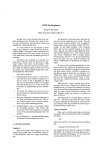
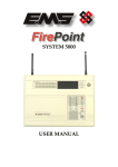
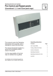
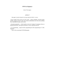
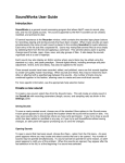
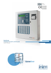
Zones 1 17 2 18 3 19 4 20 5 21 6 22 7 23 8 24 9 25 10 26 11 27 12 28 13 29 14 30 15 30 Operating instructions 16 32 SENTRI2 Control panel based Fire detection and alarm system two EN54 Parts 2 & 4 0XXXX Contents Preface ..................................................................................................... 3 Associated Documents .............................................................................. 3 Conventions............................................................................................... 3 Symbol Keys.............................................................................................. 3 Abbreviations ............................................................................................. 3 User responsibility ..................................................................................... 4 Daily........................................................................................................... 4 Weekly ....................................................................................................... 4 Limitation of false alarm............................................................................. 5 Control and indicating equipment .............................................................. 5 Control panel ............................................................................................. 5 Compact Network Node ............................................................................ 6 Repeat panels ........................................................................................... 6 Zonal Mimic panels.................................................................................... 6 Description of controls and indications ...................................................... 7 Normal condition.......................................................................................11 How to operate a ‘U’ button ......................................................................11 Weekly tests ............................................................................................ 12 How to manually raise an alarm of FIRE ................................................. 13 Automatic detection of FIRE .................................................................... 14 Fault conditions ....................................................................................... 16 Typical fault messages ............................................................................ 17 Disablement conditions ........................................................................... 18 Typical Disablement Messages ............................................................... 19 Menu controls .......................................................................................... 20 To carry out a display test ........................................................................ 21 How to change your PIN code ................................................................ 21 How to view the historic events ............................................................... 22 Cards inside the control panel ................................................................. 22 How to save changes to memory ............................................................ 23 How to view active events ....................................................................... 23 2 How to set the system clock .................................................................... 24 How to use the external printer................................................................ 25 To Switch On / Off the Printer ................................................................. 25 To action a Paper Feed ........................................................................... 25 To conduct a Printer Test ......................................................................... 25 How to enable/disable Sensing ............................................................... 25 How to enable/disable a zone ................................................................. 26 How to enable/disable an IO line ............................................................. 26 How to enable/disable aux relay.............................................................. 27 Other enable/disable options ................................................................... 27 How to view a device label ...................................................................... 27 How to view a zone label ......................................................................... 28 How to view a I/O line label ..................................................................... 28 How to view the local panel label ............................................................ 29 To view or print a map ............................................................................. 29 Editing labels ........................................................................................... 30 How to edit a device label........................................................................ 30 How to edit an Input/output line label ...................................................... 30 How to edit a zone label .......................................................................... 31 How to edit a local panel label ................................................................. 32 How to edit custom label ......................................................................... 32 Maintenance ............................................................................................ 33 Replacing the glass on a Manual Call Point ............................................ 33 Resetting the resettable element on a Manual Call Point........................ 33 Battery replacement ................................................................................ 34 Repair function ........................................................................................ 34 SenTRI2 fire system Preface Symbol Keys This is the first issue of the operating instructions for the SenTRI2 fire detection and alarm system for Sentri2 panel having enhanced loop capabilities. What you will see. Associated Documents SenTRI2 panel based system - Installation instructions - Log Book What you will hear. Conventions This is a note to highlight important text that is normally hidden in the main text. This is either a caution to prevent damage to the equipment or a warning to inform of dangerous conditions that may result in injury or death. A fire condition. LED illuminated - On. LED illuminated - Flashing. NA Not applicable Abbreviations LED - Light emitting diode (light) MCP - Manual call point NVM - Non Volatile Memory OC or O/C - Open circuit IO or I/O Input or Output SC or S/C - Short circuit [Text] - Denotes menu option that appears on display Text - Denotes physical keys on keypad 3 User responsibility User responsibility Your fire alarm system should have been designed, installed and commissioned to your site specific requirements and in accordance with the requirements of BS5839 Part 1. You should have received instructions about your system during the handover stage and must make arrangements to ensure the system is regularly tested and maintained. It is recommended that the person responsible for the fire alarm system should ensure the system is tested and maintained in accordance with the requirements of BS5839:Part 1 and become familiar with: the operation of controls and be able to interpret the indications given at the control panel keep up to date all documentation associated with the system. Any servicing work on the SenTRI2 system must be carried out by a suitably trained person, please refer to your servicing organisation. Daily BS 5839:Part 1, states that the system should be inspected daily to ensure: That a normal indication is given at the control and indicating equipment. That any previously indicated fault conditions have received appropriate attention. All system events are entered into the Log Book for future reference. That the use of the ‘area(s) that are inspected’ has not changed since the system was designed. That no unsafe practices that could lead to fire are being undertaken. Weekly When testing the system there may be a need to isolate ancillary outputs and it is important to contact the alarm receiving centre before and after the weekly test. A different manual call point of the system should be tested to ensure the system is capable of operating under alarm conditions. The operation of the alarm sounders should be checked, which also reminds the occupants that there is a fire alarm system which gives a particular sound output. The test should be performed at a regular time to avoid confusion between a test and a genuine fire alarm. The alarm receiving centre must be contacted before and after the test to check alarms are received and also to avoid unwanted alarms. 4 SenTRI2 fire system Quarterly At quarterly intervals the system should be inspected and any work necessary should be performed by a trained maintenance engineer. For help with service and maintenance please refer to your servicing organisation, see contact details entered in the log book. Control and indicating equipment On occurrence of a fire, fault or disablement event in the protect premises, the event is quickly indicated at a control and indicating equipment. The control and indicating equipments are installed in accessible location and can be operated by the person responsible for the fire system. Control panel Limitation of false alarm It is recommended that the person responsible for the fire alarm system should arrange for suitable investigation and appropriate action on occasion of every false alarm. For a system having less than 40 automatic fire detectors installed, an in-depth investigation should be instigated on occurrence of two false alarms in any rolling 12 months. For a system having more than 40 automatic fire detectors an investigation should be instigated if there has been: one false alarm for every 20 installed detectors in the system in any rolling 12 months, or two or more false alarm occurrences from a single device. The control panel is the heart of the system. It is normally located near to the main entry or exit point of the protected premises. The control panel continuously monitor devices that are connected to each device loop. The device loop cable is routed through the protected premises to cover all areas with both ends of the loop terminating at the control panel. On the loop cable are installed devices such as fire sensors, that constantly monitor the environment for fire. Alarm devices on the loop provide alert and evacuation alarm to warn occupants in the protected premises in the event of a fire. Zones 1 17 2 18 3 19 4 20 5 21 6 22 7 23 8 24 9 25 10 26 11 27 12 28 13 29 14 30 15 30 16 32 two EN54 Parts 2 & 4 Zone indicators (to locate the area(s) in a building where fire(s) are detected) 0XXXX 5 Control and indicating equipment Repeat panels Zonal Mimic panels There may be one or more repeat panels installed in the protected premises to provide secondary indications of the system condition. The larger repeat panel additionally provide system controls. The repeat panels are usually located near to secondary entry and exit points of the protected premises. There may also be a number of mimic and zonal mimic panels installed in the protected premises, to provide visual indications in a graphical and zonal format. Normally one is installed next to the main control panel. There may be additional panels installed in other areas of the protected premises to cover sub division of the premises. Zones 1 2 3 4 17 18 19 20 5 21 6 22 7 23 8 24 9 25 10 26 11 27 12 28 13 29 14 30 15 30 16 32 Repeat indicator panel (provides system indications) Repeat panel (provides system indications and controls) 6 A3 Zonal panel (Provides zonal indication of events) SenTRI2 fire system Description of controls and indications Open the front door to reveal the controls. 1 17 Zones Fault Message Display 2 18 3 19 4 20 5 21 6 22 7 23 8 24 9 25 10 26 11 27 Panel healthy 12 28 13 29 15:45 15 30 16 32 Fire Verify Power Fault SenTRI 2 Fire System Designed to EN54 Pt 2 & 4 System Fault Access level 1 Controls to scroll fire events Sounder Delay CB253 Test CB254 Disablement Power two Previous EN54 Parts 2 & 4 Next Menu On/Off Cancel Buzzer F1 Key lock to open the outer door Outer door 14 30 Indications F2 F3 F4 Inner door Sound Alarms Verify Enter Silence Alarms ABC DEF 1 2 3 GHI JKL MNO U1 U2 4 5 6 PQRS TUV WXYZ 7 8 THRU Operating instructions and Log Book Access level 2 Controls INS Reset 9 BKSP 0 DEL 7 Description of controls and indications Indicators Description Display The Display provides messages of the system status / events by means of 8 lines by 40 characters per line display. Zones Power 1 (red) Secret-until-lit fire zone indicators. When the “Zones” text and number(s) are illuminated it indicates that a FIRE has been detected in the indicated zone(s). When illuminated it indicates that a supply to the panel is present. (green) When illuminated it indicates that a FIRE has been detected in the protected premises. Fire (red) Verify (amber) When illuminated it indicates that the Verify button has been pressed and the alarm sounders in the system are delayed from sounding. When illuminated it indicates that a FAULT has been detected in the fire detection and alarm system. Fault (amber) System Fault (amber) When illuminated it indicates that a fault has occurred with the system processor. It is important to investigate this fault because the fire system may not be able to detect fires. When illuminated it indicates that a part of the system has been disabled. Disablement (amber) CB253 or CB254 When illuminated it indicates command builds 253 or 254 has been activated. (amber) Power Fault Sounder Delay Test 8 When illuminated it indicates the battery or mains supply to the panel has failed. (amber) (amber) When illuminated (always with either the FAULT light or the DISABLEMENT light) it indicates that there is a sounder fault (flashing indication) or sounder disablement (steady indication). When illuminated it indicates that one or more delay blocks are setup on the panel. (amber) When illuminated it indicates one or more zones are in Test mode. (amber) SenTRI2 fire system Controls Description Menu On/Off Pressing the Menu On/Off will enable/disable the on screen menu facility, which gives access to the system menus. F1 to F4 The ‘Fn’ buttons are used to select a function and sub functions at the panel menus that appear on the display. Each option in the menus corresponds to one of the function buttons and pressing a button will select the option which appears above it on the display. Cancel Buzzer The Cancel Buzzer button when pressed will stop the internal panel buzzer from sounding. Sound Alarms Pressing the Sound Alarms button will sound all the system alarms. This button is only pressed in an emergency or at other agreed times, for example when conducting a sounder test or practice evacuation. Silence Alarms Pressing the Silence Alarms button will silence the system alarms. Reset Pressing the Reset button will clear any fires and return the panel to its normal condition. If a fire condition occurs immediately after reset then the indicated device should be investigated. Verify If the Verify facility has been set up, then pressing the Verify button in the event of a fire condition, increases the time delay before the sounders are activated. This gives the user time to investigate the cause of the alarm and the option of cancelling the alarm within the delay time period. U1 U2 These buttons can be configured during commissioning to action user-defined tasks, such as the disablement of devices in areas where smoke may be generated due to maintenance work or where plant shutdown is required. 9 Description of controls and indications Controls These four buttons are used to scroll the displayed text. ABC DEF 1 2 3 GHI JKL MNO 4 5 6 PQRS TUV WXYZ 7 8 9 THRU INS BKSP 00 When entering a label each press of a key will scroll the character string, for example: key 2 will scroll A B C 2 a b c. key 1 will scroll 1 ? , . ; & * / The bottom row of text keys explained: The U button is used to enter a SPACE between characters The INS key allows text to be moved one position to the right The DEL key allows a character to be deleted The BKSP button will delete previous character. When entering a data range, such as a range of devices the key THRU ( - ) is used, for example 1 - 5. DEL This button is pressed to acknowledge an entry of data such as a label. Enter 10 SenTRI2 fire system Normal condition How to operate a ‘U’ button When a system is operating normally with no fault or disablement present then the panel’s display shows: ‘Panel healthy’ message and ‘Network Healthy’ message and only the ‘Power’ green indicator is lit. The U1 and U2 buttons may have been configured during commissioning to action user-defined tasks, such as the disablement of devices in areas where smoke may be generated due to temporary maintenance work or to action a plant shutdown if required. The function of these ‘U’ buttons should be written on the label that is fitted on the back of the panel’s outer door. With the panel door open: two On EN54 Parts 2 & 4 Flashing Fault Fire Panel healthy 15:45 Verify Power Fault System Fault SenTRI 2 Fire System Designed to EN54 Pt 2 & 4 You can activate the predefined task by operating the ‘U’ button. Un Press: n - can be 1 or 2. Sounder Delay CB253 Test CB254 Disablement Power Previous To activate a ‘U’ button. Next 11 Weekly tests Weekly tests Every week during normal working hours the fire detection and alarm system should be tested. It is important to inform the alarm receiving centre of the fire test. The weekly fire test can be carried out at a manual call point without breaking the call point glass. Turn the test key anticlockwise one quarter of a turn and remove it from the call point. With the panel door open: To cancel buzzer Cancel Buzzer Insert the test key into the keyhole located on the bottom-centre front face of the call point and turn the key one quarter of a turn clockwise. Manual Call point Press: Display reads: ‘Buzzer cancelled’ To silence alarms Test Key On To reset system Fire 15:45 1stFIRE:MCP:Zone 1 Verify Power Fault System Fault First Fire occurred at: Time: 13:43.10 Sun 17 To return the system to normal condition clear any residual smoke or heat from sensors and replace the glass in any manual call points where the glass was broken. Reset Sounder March 2013 Delay CB253 Test CB254 Disablement Power Previous Next At this point the test key is retained in the call point. Check the alarms are sounding in the building and an indication is given of the fire event. 12 Press: Display reads: ‘Alarms silenced’ Flashing 1 Fault When the test is complete, the alarm sounders can be silenced. Silence Alarms Panel buzzer Zones You can stop the panel buzzer from sounding. Press: Display reads ‘System being Reset please wait....’ Record the event Make an entry in the log book of the event for future reference. SenTRI2 fire system With the panel door open: How to manually raise an alarm of FIRE If you see a fire in the protected premises and want to raise a fire alarm to warn occupants in the building, you can do this manually by: Going to the nearest manual call point that is located away from the fire hazard. Press hard with a thumb onto the centre of the glass until it breaks. Manual Call point To cancel buzzer You can stop the panel buzzer from sounding. Cancel Buzzer Press: Display reads: ‘Buzzer cancelled’ To silence alarms When the emergency is over the alarm sounders can be silenced. Silence Alarms Press: Display reads: ‘Alarms silenced’ Panel buzzer To reset system On Zones Flashing 1 Fault Fire 15:45 1stFIRE:MCP:Zone 1 Verify Power Fault System Fault To return the system to normal condition clear any residual smoke or heat from sensors and replace the glass in any manual call points where the glass was broken. Ensure the fire system is checked by your servicing organisation if there has been fire damage in the protected area. First Fire occurred at: Time: 11:43.10 Sun 17 Sounder Reset March 2013 Delay CB253 Test CB254 Disablement Press: Display reads ‘System being Reset please wait....’ Power Previous Next Record the event Make an entry in the log book of the event for future reference. 13 Automatic detection of FIRE With the panel door open: Automatic detection of FIRE A fire in your protected premises is automatically sensed at any one of the fire detection devices installed in the building, such as a sensor or a fire input from an interface. The control panel actions the alarm sounders in the system and at the same time gives the details of the fire event. The event indication is repeated at all repeat indicator panels in the system. To cancel buzzer Cancel Buzzer Press: Display reads: ‘Buzzer cancelled’ To silence alarms On Flashing Press: Display reads: ‘Alarms silenced’ 1 Fault To reset system Fire 15:45 1stFIRE:MCP:Zone 1 Verify Power Fault System Fault When the emergency is over the alarm sounders can be silenced. Silence Alarms Panel buzzer Zones You can stop the panel buzzer from sounding. First Fire occurred at: Time: 08:43.10 Sun 17 Sounder March 2013 Delay CB253 Test CB254 Disablement Power Previous To return the system to normal condition clear any residual smoke or heat from sensors and replace the glass in any manual call points where the glass was broken. Ensure the fire system is checked by your servicing organisation if there has been fire damage in the protected area. Reset Next Press: Display reads ‘System being Reset please wait....’ Record the event 14 Make an entry in the log book of the event for future reference. SenTRI2 fire system Multiple fires Previous Next F2 F3 Use the [Previous] or [Next] buttons to scroll the fire events. The 1st Fire will always appear at top of display. All subsequent fires appear beneath the 1st Fire. Zones 1 The zonal indicators show zones in fire condition. If the panel is configured, the first zone to go into a fire condition may be indicated by a flashing zone number, all other zones in fire give a steady indication. Each fire is logged in the Historic Events log, which can be recalled using the menus. See How to view the Historic Events. To verify an alarm (If required by site procedures) Upon receipt of a fire condition the alarm sounders in the system can be delayed from sounding by using the Verify button. This allows time to investigate the cause of the alarm. Note the delayed sounders will operate after the verify period has timed-out. Verify Press: Verify 15 Fault conditions With the panel door open: Fault conditions A fault in the system, such as failure of mains power to the panel or removal of any monitoring device will cause a Fault condition to appear at the control panel. The control panel will provide details of the event, this event indication is repeated at all repeat panels and may also be displayed at zonal and mimic panels in the system. Panel buzzer Fault Power Fault On Flashing Fire Fault 1 Time:13:45.44 Sun 17 March 2013 Monitored input O/C 15:45 Verify Sounder System Fault Delay CB253 Test CB254 Disablement Power Previous Next Only the trained engineer who is responsible for the fire alarm system must attempt any fault rectification work. For advice please call your servicing organisation, see contact details in the Log book. 16 To cancel buzzer You can stop the panel buzzer from sounding. Cancel Buzzer Press: Display reads: ‘Buzzer cancelled’ What must be done? You need to ensure the panel is returned to normal condition. All fault repairs must be undertaken by engineers responsible for the system. Refer to the contact details in the log book. Record the event Make an entry in the log book of the event for future reference. Multiple faults The number ‘n’ following the word ‘Fault’ located top left on the display denotes the number of faults present in the system. Each fault is logged in the Historic Events log, which can be recalled using the menus. See How to view the Historic Events. SenTRI2 fire system Typical fault messages The table below shows some of the more typical fault messages and indications that may appear at the panel if there are faults in the system. It also gives the meaning and possible rectification action for each fault. On Flashing Message Indication Meaning Action Mains failed Fault Power Fault The mains supply to the Control panel has failed. Restore the mains supply to the control panel. Battery discharged n Fault Power Fault The battery supply to the Control Panel has been fully discharged. Check the battery and replace if necessary. Battery disconnected Fault Power Fault The battery supply to the Control Panel has been disconnected. Reconnect the battery. Monitored line input OC or SC Fault The monitored line input has an open or short circuit fault. Check the wiring and ensure the end-ofline device is connected in the circuit. Master Alarm(s) OC or SC n Fault Sounder There is an open or short circuit fault on the master alarm wiring. Check the wiring. Ensure the end-of-line device is connected in the circuit. Lost Device Fault Sounder The Device is not communicating with the Control Panel via the Loop. Additional indication given if it is a Sounder device. Check the connections to the device. Sensor out of specification Fault The device indicated is not functioning correctly. Device needs replacing. Wiring changed SC at card n Fault There is a short circuit on the loop n wiring. Identify the device where a cable fault has occurred and remove the fault. Interface input OC /SC Fault There is an open or short circuit on the input line of an interface. Locate and remove the wiring fault. Ensure the end-of-line device is connected in the circuit. Device Mains failed Fault There is a mains supply failure at an interface unit, repeat panel or mimic panel Check the fuse and mains supply to the equipment. Device Battery fault Fault The battery supply at an interface unit, repeat panel or mimic panel has failed the load test. Check the battery and replace if necessary. 17 Disablement conditions Disablement conditions A disablement condition is the manual or automatic disablement of a part of the fire detection system. An automatic disablement may be pre-configured for your premises to disable smoke sensors during the normal working hours in areas where smoke or dust may be present. A manual disablement may be necessary where building work is being undertaken that could result in a false alarm. On Fault Power Fault Disable: 1 Time:13:45.44 Sun 17 March 2013 Device Disabled at card 1 15:45 Flashing Fire Verify Sounder System Fault Delay CB253 Test CB254 Disablement Power Previous Next This indication is only given if a sector, sounder device or master alarms in the system are disabled. What must be done? Investigate the reason for the disablement and re-instate the devices if appropriate. Record the event Where necessary make an entry in the log book of the event for future reference. Multiple Disablements The number ‘n’ following the word ‘Disable’ located top left on the display denotes the number of disablements present in the system. Each disablement is logged in the Historic Events log which can be recalled using the menus, see How to view the Historic Events. 18 SenTRI2 fire system Typical Disablement Messages The following table shows some typical disablement messages and indications that may appear at the panel. Flashing On Message Indication Meaning Action Zone Disabled at card n Disablement The zone specified has been manually or automatically disabled. If manually disabled then investigate and if necessary re-enable the zone. Device disabled at card n Disablement A device connected to the loop circuit has been manually or automatically disabled. Additional indication is given if it is a sounder device. If manually disabled then investigate and if appropriate re-enable the device. The fire alarm sector on loop n has been manually or automatically disabled. If manually disabled then investigate and if appropriate, re-enable the sector. Sounder Sector disabled at card n Disablement Sounder Disabled Aux Relay n Disablement The auxiliary relay n in the control panel has been manually or automatically disabled. If manually disabled then investigate and if appropriate, re-enable the aux relay. Master alarm(s) disabled Disablement The master alarms have been manually or automatically disabled. If manually disabled then investigate and if appropriate, re-enable the master alarms. Sounder Any changes to the setting of an automatic disablement must only be attempted by a trained engineer who is responsible for the fire alarm system, see contact details in the Log book. 19 Menu controls Menu controls Panel beeps on button press On Fault Flashing Fire 15:45 Power Fault Sounder SenTRI 2 Fire System Designed to EN54 pt 2 & 4 System Fault Delay ] [ Info ] [ Test/Eng] Disablement CB254 Power Menu On/Off F1 Previous Next F2 F3 Cancel Buzzer F4 The MENU ON/OFF button activates the function keys F1 to F4 for the selection of menu prompts that appear above the function keys on the display. At any level in a menu, single press of the MENU ON/OFF key aborts an operation. However as an alternative the [Quit] option can be selected to exit the function mode. If the time taken between key presses exceeds five minutes, then the control panel will automatically remove the menu options from the display and give a system status indications. The [Params] option is a Help function to provide information to the user regarding the type of input data required. 20 An open access to controls under User code is undesirable, so it is recommended that a customer password is setup. CB253 Test [Control] [ Set Up Verify Most of the functions in the [Control], [Setup] and [TestEng] menu options are protected with password entry. The password is programmed during the commissioning of the system and is passed on to the site person responsible for the fire alarm system. Where a password code is not set up, there is an open entry to operate the controls under [User Code]. Where this is true the instructions for entering the access code, password (or PIN) in the following instructions should be ignored. SenTRI2 fire system To carry out a display test How to change your PIN code You can test the message display and the indicators on the control panel. The following terms: Password, PIN, Usercode and Access code mean the same and are used interchangeably. A Customer user PIN code (password) is normally set up by the servicing organisation during commissioning of the fire alarm system. The customer PIN code is set up for the end user. The person responsible for the fire alarm system should be aware of this PIN code. For security the PIN should be changed on a regular basis. a. Press the MENU ON/OFF key and then the F4 key to select [Test/Eng]. b. Press the F1 key to select [Disp Test]. Check that the following things happen: The display clears, the indicators illuminate, the buzzer sounds two distinct tones and then the display shows the system status message. The display test lasts for about 4 seconds. A previously created PIN can be changed: a. Press the MENU ON/OFF button. b. Press the F4 button to select [Test/Eng]. c. Press the F4 button to select [UserCode]. Use the keypad to input your existing access code and then press the Enter button. d. Press the F1 button to select [NewPass]. At the flashing cursor using the keypad input the PIN code and press the Enter button. Notice ‘New access code set up’ appears on the display. Any changes made to the PIN code must be backed-up to the panel memory. If this is not done then the previous PIN is restored on resetting the panel, see section on ‘How to save changes to memory’. It is not necessary to backup the password at a repeat panel. 21 How to view the historic events How to view the historic events Cards inside the control panel Up to 255 events are stored in the Historic log of the panel. To view the Historic log. The control panel uses the following card reference numbers. a. Press MENU ON/OFF. Card 0 is always the Main controller board (MCB), also referred to as a local controller. b. Press the F3 button to select [Info]. Ignore step c. if an external printer is not fitted or is switched off. c. To display the event(s): Press the F1 button to select [Display]. Notice ‘Display’ appears on the display. To print the event(s): Press the F2 button to select [Print]. Notice ‘Print’ appears on the display. d. Press the F2 button to select [Historic]. Notice ‘Historic’ followed by a flashing cursor appears on the display. e. Use the keypad to input an event number 1 to 255. If you want to view events at another node in a networked system, then you will need the node number. Select [Node] and enter the node number. The event number ‘1’ is always the most recent event. f. 22 Press the F2 button to select [Enter]. Notice the required event(s) are displayed or printed depending on your selection. Card 1 and Card 2 are always the Loop processor cards that monitor and control the devices on a loop circuit within the protected premises. Card 14 is always the memory that resides on the Main controller board. SenTRI2 fire system How to save changes to memory How to view active events If you make any changes to a Labels or Password then you must save these to the NVM (Non Volatile Memory) or Memory of the panel. An active event is an event that is still present and has not cleared. You can view all active Fire, Fault or Disablement events. Changes made to labels and password can be saved to the panel memory (NVM), this can only be done when there are no disablements present on the system. The following procedures assume a customer password (PIN) is setup at the panel. a. Press the MENU ON/OFF button. b. Press the F2 button to select [Set Up]. c. Press the F4 button to select [UserCode]. At the flashing cursor using the keypad input your PIN code and then press the Enter button. d. Press the F4 button to select <etc> and then press the F3 button to select [Save]. The ‘Save’ option is only available if Access level 2 PIN is set up. e. Press the F2 button to select [Enter]. Observe confirmation of data backed up. a. Press MENU ON/OFF. b. Press the F3 button to select [Info]. Ignore step c. if an external printer is not fitted or is switched off. c. To display the event(s): Press the F1 button to select [Display]. Notice ‘Display’ appears on the display. To print the event(s): Press the F2 button to select [Print]. Notice ‘Print’ appears on the display. d. Press the F1 button to select [Active]. Notice ‘Active’ appears on the display. To view events on the local panel and on a card by card basis then press the F3 button to select [Card], notice ‘on card’ appears on the display. Enter the card number. To view events at another node in a networked system, then you will need to know the node number. Press the F4 button to select [Node] and enter a node number from a range 1 to 255. e. Press the F2 button to select [Enter]. Notice all of the active Fire, Fault and Disablement events are displayed in turn. Press the F2 [Previous] and F3 [Next] button to scroll through the displayed events. f. Press the F4 button to select [Quit], when viewing of events is complete. 23 How to set the system clock How to set the system clock An incorrect setting of the system clock will affect any time related sensor configuration and consequently results in incorrect event time information. a. Press the MENU ON/OFF key and then the F2 key to select [Set Up]. b. Press the F4 key to select [User Code]. At the flashing cursor using the keypad input the PIN code and press the Enter button. c. Press the F1 key to select [Set Clock]. The system clock is displayed on the screen. Check the hour digits are flashing. d. Press the F2 or F3 key to [Retard] or [Advance] to the desired setting. e. Press the F1 key to select [Next]. Check that the Minute digits are now flashing. f. Press the F2 or F3 key to [Retard] or [Advance] to the desired setting. g. Press the F1 key to select [Next]. Check that the Date digits are now flashing. h. Press the F2 or F3 key to [Retard] or [Advance] to the desired setting. i. 24 Press the F1 key to select [Next]. Check that the Month digits are now flashing. j. Press the F2 or F3 key to [Retard] or [Advance] to the desired setting. k. Press the F1 key to select [Next]. Check that the Year is now flashing. l. Press the F2 or F3 key to [Retard] or [Advance] to the desired setting. m. Press the F4 key to select [Enter]. Check that the display now shows the new time and date. Any changes made to the time and date will be automatically sent to the repeat panels in the system. The system clock adjusts automatically for Day light saving, if set up during commissioning. Now ‘Save’ the changes made to the clock settings. SenTRI2 fire system How to use the external printer How to enable/disable Sensing Assuming an external printer is connected to the panel: It is only possible to disable a Manual Call Point (MCP) individually, not as part of a range. DISABLING A MCP IS NOT RECOMMENDED. To Switch On / Off the Printer a. Press the MENU ON/OFF key. b. Press the F1 key to select [Control]. c. Press the F3 key to select [Printer]. Check that ‘Printer’ appears on the screen. d. Press the F3 key to select [On] / [Off] and then press the F2 key to select [Enter]. ‘Printer is on/off’ is displayed. A sensing device such as a sensor or MCP in the system can be disabled/enabled. You will need the device and loop numbers, this information can be found in the site specific documents held by the person responsible for the fire system. a. Press the MENU ON/OFF key. To action a Paper Feed b. Press the F1 button to select [Control]. a. Press the MENU ON/OFF key. c. Press the F4 button to select [UserCode]. At the flashing cursor using and the keypad input your PIN code and then press the Enter button. b. Press the F1 key to select [Control]. c. Press the F3 key to select [Printer]. Check that ‘Printer’ appears on the screen. d. Press the F2 key to select [Paper Fd]. Note the display and menu prompts are cleared. Printer performs 8 line feeds. d. To disable a device: Press the F2 button to select [Disable]. To enable a device: Press the F1 button to select [Enable]. The display shows either ‘Enable’ or ‘Disable’. a. Press the MENU ON/OFF key. e. Press the F1 button to select [Sensing]. Notice ‘Device’ followed by a flashing cursor appears on the display. Use the keypad to input a device number or range (1-200). b. Press the F1 key to select [Control]. f. To conduct a Printer Test c. Press the F3 key to select [Printer]. Check that ‘Printer’ appears on the screen. d. Press the F1 key to select [Test]. Note the display and menu prompts are cleared. Press the F2 button to select [Loop]. Notice ‘Loop’ followed by a flashing cursor on the display. Use the keypad to input a loop number or range (1-2). g. Press the F2 button to select [Enter]. This is confirmed by: ‘Device(s) enabled’ or ‘Device(s) disabled’. The Disablement light is lit upon disablement of the divice. e. Check that the printer provides a listing of all the characters it is capable of printing. 25 How to enable/disable a zone How to enable/disable a zone How to enable/disable an IO line A zone is a subdivision of your premises that is protected by the fire alarm system. There can be up to 128 zones configured in a system. Any zone operation can be disabled or enabled. You will need to know the zone number, this can be found in the site specific documentation held by the person responsible for the fire alarm system. An interface input/output line can be disabled or enabled. You will need to know the IO line, device and loop numbers, these numbers can be found in the site specific documents held by the person responsible for the fire system. An output line of an interface unit may be assigned to a sector and can only be disabled by disabling that sector. This has the effect of also disabling all other devices in the sector. a. Press the MENU ON/OFF key. b. Press the F1 button to select [Control]. a. Press the MENU ON/OFF key. c. Press the F4 button to select [UserCode]. At the flashing cursor using the keypad input your PIN code and then press the Enter button. b. Press the F1 button to select [Control]. d. To disable a zone: Press the F2 button to select [Disable] or press the F1 button to select [Enable]. e. Press the F4 button to select <etc> and then press the F2 button to select [Zone]. At the flashing cursor using the keypad input a zone number or range (1-128). f. 26 Press the F2 button to select [Enter]. Notice the action has been processed and a message appears on the display ‘Zone n enabled’ or ‘Zone n disabled’. The Disablement light will be illuminated upon disablement of any zone. c. Press the F4 button to select [UserCode]. At the flashing cursor using the keypad input your PIN code and then press the Enter button. d. To disable an IO line press the F2 button to select [Disable] or press the F1 button to select [Enable], the display reads ‘Enable’ or ‘Disable’. e. Press the F2 button to select [IO Line]. At the flashing cursor using the keypad input an IO line number. f. Press the F2 button to select [Device]. At the flashing cursor using the keypad input a device number from a range 1 to 200. g. Press the F2 button to select [Loop]. At the flashing cursor using the keypad input a loop number from a range 1 to 2. h. Press the F2 button to select [Enter]. Notice the action has been processed and a message appears on the display: ‘IO line disabled/ enabled at Card n’. The disablement light will illuminate upon disablement of an IO line. SenTRI2 fire system How to enable/disable aux relay How to view a device label The control panel has two auxiliary relays that provides voltage free contacts to control external equipment in the event of a fire or fault condition. The operation of the relays can be disabled or enabled. Each device in the sytem is given a location label at the time the system is commissioned to identify its installation position. To view a device label you will need to know the device address and the loop on which it resides, which can be found in the site specific documentation held by the person responsible for the fire alarm system. a. Press the MENU ON/OFF key. b. Press the F1 button to select [Control]. a. Press the MENU ON/OFF button. c. Press the F4 button to select [UserCode]. At the flashing cursor using the keypad input your PIN code and then press the Enter button. b. Press the F3 button to select [Info]. Ignore step c. if an external printer is not fitted or is switched off. d. To disable the auxiliary relay press the F2 button to select [Disable] or press the F1 button to select [Enable]. This puts ‘Disable’ or ‘Enable’ on the display. c. To display a device label press the F1 button to select [Display] or to print a device label press the F2 button to select [Print]. Notice ‘Display’ or ‘Print’ appears on the screen. e. Press the F4 button three times selecting <etc> on each occasion and then press the F2 button to select [Aux Rly]. At the flashing cursor using the keypad input an auxiliary relay number or range (1-2). f. Press the F2 button to select [Enter]. Notice the action has been processed and a message appears on the display: ‘Aux Rly n disabled/enabled’. The Disablement light will illuminate upon disablement of an auxiliary relay. Other enable/disable options There are other options such as Sounders, Command Build, Group, and Communication that are accessible for enablement and disablement, for further advice contact your servicing organisation, see the Log book for contact details. d. Press the F4 button to select <etc>. e. Press the F2 button to select [Label]. Notice ‘Label’ appears on the display. f. Press the F3 button to select [Device]. Notice ‘Device’ followed by a flashing cursor appears on the display. Use the keypad to input a Device number or range (1-200). g. Press the F2 button to select [Loop]. Notice ‘Loop’ followed by a flashing cursor appears on the display. Use the keypad to input a loop number (1 or 2). h. Press the F2 button to select [Enter]. Notice the selected label information is either displayed or printed. 27 How to view a zone label How to view a zone label How to view a I/O line label A zone is a subdivision of a building used for fire detection. To view a zone label you will need to know the zone number. You can find this information in the site specific documentation, held by the person responsible for the fire alarm system. An interface unit can have up to four input/output (IO) lines. Each line may have been given a label for display during an event. To view an IO line label you will need to know the interface device address, the IO line number and the loop number, which can found in the site specific documentation held by the person responsible for the fire alarm system. a. Press the MENU ON/OFF button. b. Press the F3 button to select [Info]. Ignore step c. if an external printer is not fitted or is switched off. c. To display a zone label press the F1 button to select [Display] or to print a zone label press the F2 button to select [Print]. Notice ‘Display’ or ‘Print’ appears on the screen. d. Press the F4 button to select <etc>. e. Press the F2 button to select [Label]. Notice ‘Label’ appears on the display. f. Press the F4 button once to select <etc>. g. Press the F1 key to select [Zone]. Notice ‘Zone’ followed by a flashing cursor appears on the display. Use the keypad to input a Zone number from a range 1-128. h. Press the F2 key to select [Enter]. Notice the selected label information is either displayed or printed. 28 a. Press the MENU ON/OFF button. b. Press the F3 button to select [Info]. Ignore step c. if an external printer is not fitted or is switched off. c. To display an I/O line label press the F1 button to select [Display] or to print an I/O line label press the F2 button to select [Print]. Notice ‘Display’ or ‘Print’ appears on the screen. d. Press the F4 button to select <etc>. e. Press the F2 button to select [Label]. Notice ‘Label’ appears on the display. f. Press the F2 button to select [IO Line]. Notice ‘IO Line’ followed by a flashing cursor appears on the display. Use the keypad to enter an input/ output line number from a range 1 to 4. g. Press the F2 button to select [Device]. Notice ‘Device’ followed by a flashing cursor on the display. Use the keypad to enter a Device number (1-200). h. Press the F2 button to select [Loop]. Notice ‘Loop’ followed by a flashing cursor appears on the display. Use the keypad to input a loop number (1 or 2). i. Press the F2 button to select [Enter]. Notice the selected label information is either displayed or printed. SenTRI2 fire system How to view the local panel label To view or print a map When there is a network of control panels connected together in a system then each panel is usually given an identification label, also referred to as the Local panel label. A map provides information on devices that are connected to a loop off a control panel in a fire alarm network. a. Press the MENU ON/OFF button. b. Press the F3 button to select [Info]. Ignore step c. if an external printer is not fitted or is switched off. c. To display a local panel label press the F1 button to select [Display] or to print a local panel label press the F2 button to select [Print]. Notice ‘Display’ or ‘Print’ appears on the screen. d. Press the F4 button to select <etc>. e. Press the F2 button to select [Label]. Notice ‘Label’ appears on the display. f. Press the F4 button once to select <etc>. g. Press the F2 key to select [Local]. Notice ‘Local’ appears on the display. h. Press the F2 key to select [Enter]. Notice the selected label information is either displayed or printed. a. Press the MENU ON/OFF button. b. Press the F3 button to select [Info]. Ignore step c. if an external printer is not fitted or is switched off. c. To display a loop map press the F1 button to select [Display] or to print a loop map press the F2 button to select [Print]. Notice ‘Display’ or ‘Print’ appears on the screen. d. Press the F4 button to select <etc>. e. Press the F4 button to select [UserCode]. Notice a message on the display ‘Enter access code’, followed by a flashing cursor. Use the keypad to input your PIN and then press Enter button. f. Press the F3 button to select [Loop Map] or [Map]. g. On selecting [Map] you have a choice of either [Loop Map] or [Net Map]. h. On selecting [Loop Map] notice ‘Loop Map’ followed by a flashing cursor appear on the display. i. On selecting [Net Map] notice ‘Node’ followed by a flashing cursor appear on the display. j. Use the keypad to enter the loop number or node number and then press F3 to select [Enter]. Notice the map is either printed or displayed. 29 Editing labels followed by a flashing cursor appears on the display. Editing labels Any changes to labels must be backed up to the Memory, see the section ‘How to save changes to the memory’. How to edit a device label There can be up to 200 devices connected to a loop, devices like fire sensors and manual call points. Each device can be given a label to identify its location in the system. Devices in your system may have already been given labels and these labels can be changed. To edit a device label you will need to know the device number and the loop on which it resides. You can find this information in the site specific documentation, held by the person responsible for the fire system. a. Press the MENU ON/OFF button b. Press the F2 button to select [Set Up]. c. Press the F4 button to select [UserCode]. A message is displayed: ‘Enter access code’ followed by a flashing cursor. Use the keypad to input your PIN and then press the Enter button. d. Press the F4 button once to select <etc>. e. Press the F1 button to select [Modify]. Notice ‘Modify’ appears on the display. f. Press the F1 button to select [Label]. Notice ‘Label’ appears on the display. g. Press the F3 button to select [Device]. Notice ‘Device’ 30 h. Use the keypad to input a Device number. i. Press the F2 button to select [Loop]. Notice ‘Loop’ followed by a flashing cursor on the display. Use the keypad to input a loop number either 1 or 2. j. Press the F2 button to select [Enter]. Notice the previous label appears on the display with a flashing first character to prompt the modification, if there is no label the line is blank. k. Use the keypad to enter a label of up to 32 characters in length (28 for MCP) and then press the Enter button. How to edit an Input/output line label Each input / output (IO) line of an interface unit can be given a label and a previously entered label can be modified. To edit an IO line label you will need to know the IO line number, interface device number and the loop number it is connected to. You can find this information in the site specific documentation, held by the person responsible for the fire alarm system. a. Press the MENU ON/OFF button. b. Press the F2 button to select [Set Up]. c. Press the F4 button to select [UserCode]. Notice a message on the display ‘Enter access code’, followed by a flashing cursor. Use the keypad to input your PIN and then press Enter button. d. Press the F4 button once to select <etc>. e. Press the F1 button to select [Modify]. Notice ‘Modify’ appears on the display. SenTRI2 fire system f. Press the F1 button to select [Label]. Notice ‘Label’ appears on the display. g. Press the F2 button to select [IO Line]. Notice ‘IO Line’ followed by a flashing cursor on the display. Using the keypad enter an input/output number from a range 1 to 4. h. Press the F3 button to select [Device]. Notice ‘Device’ followed by a flashing cursor appears on the display. Use the keypad to input a Device number from the range 1 to 200. i. j. Press the F2 button to select [Loop]. Notice ‘Loop’ followed by a flashing cursor on the display. Use the keypad to input a loop number 1 or 2. Press the F2 button to select [Enter]. Notice the previous label appears on the display with a flashing first character to prompt you to edit a label. If there is no label then the line is blank. k. Using the keypad enter a label of up to 32 characters in length and then press the Enter button. How to edit a zone label Each zone can be given a label and an entered label can be modified. To edit a zone label you will need to know the zone number. You can find this information in the site specific documentation, held by the person responsible for the fire alarm system. a. Press the MENU ON/OFF button. b. Press the F2 button to select [Set Up]. c. Press the F4 button to select [UserCode]. Notice a message on the display ‘Enter access code’, followed by a flashing cursor. Use the keypad to input your PIN and then press Enter button. d. Press the F4 button once to select <etc>. e. Press the F1 button to select [Modify]. Notice ‘Modify’ appears on the display. f. Press the F1 button to select [Label]. Notice ‘Label’ appears on the display. g. Press the F4 button once to select <etc>. h. Press the F1 button to select [Zone]. Notice ‘Zone’ followed by a flashing cursor appears on the display. Using the keypad enter a number from a range 1 to128. i. Press the F2 button to select [Enter]. Notice the previous label appears on the display with a flashing first character to prompt you to edit the label. If there is no label then the line is blank. j. Using the keypad to enter a label of up to 32 characters in length and then press the Enter button. 31 How to edit a local panel label How to edit a local panel label How to edit custom label A label is normally given to the control panel to identify its location in a network. A previously entered label can be modified. A custom message or label is displayed beneath the Designed to EN54 Pt 2 & 4 line on the panel. The message or label can be up to 40 characters in length and it can be contact information of the person responsible for the fire alarm system or it can have contact phone number of the servicing organisation. Example: “For service call: phone number”. a. Press the MENU ON/OFF button. b. Press the F2 button to select [Set Up]. c. Press the F4 button to select [UserCode]. Notice a message on the display ‘Enter access code’, followed by a flashing cursor. Use the keypad to input the PIN and then press Enter button. d. Press the F4 button once to select <etc>. A previously entered label can be modified. a. Press the MENU ON/OFF button. b. Press the F2 button to select [Set Up]. e. Press the F1 button to select [Modify]. Notice ‘Modify’ appears on the display. c. Press the F4 button to select [UserCode]. Notice a message on the display ‘Enter access code’, followed by a flashing cursor. Use the keypad to input the PIN and then press Enter button. f. d. Press the F4 button once to select <etc>. Press the F1 button to select [Label]. Notice ‘Label’ appears on the display. g. Press the F4 button once to select <etc>. e. Press the F1 button to select [Modify]. Notice ‘Modify’ appears on the display. h. Press the F2 button to select [Local]. Notice ‘local’ appears on the display. f. i. g. Press the F4 button once to select <etc>. j. 32 Press the F2 button to select [Enter]. Notice the previous label appears on the display with a flashing first character to prompt you to edit the label. If there is no label then the line is blank. Using the keypad to enter a label of up to 40 characters in length and then press the Enter button. Press the F1 button to select [Label]. Notice ‘Label’ appears on the display. h. Press the F3 button to select [Custom]. Notice ‘Custom’ appears on the display. i. Press the F2 button to select [Enter]. Notice the previous label appears on the display with a flashing first character to prompt you to edit a label. If there is no label then the line is blank. j. Using the keypad enter a label of up to 40 characters in length and press the Enter button. SenTRI2 fire system Maintenance Replacing the glass on a Manual Call Point a. Disengage the front cover from the call point assembly using the end of the test key. Insert the key into the slots ‘E’ on the underside of the call point to compress the retaining tabs and the from the bottom edge lift out the cover. b. Carefully remove broken glass from the call point. E YELLOW ARM Take appropriate precautions when clearing the broken glass to prevent injury. c. Insert the key in the keyhole and turn the key such that the tab is at position ‘F’ and then insert a new glass as shown. Ensure the glass has engaged into the yellow arm. d. Hook the front cover onto the top edge of the call point assembly and then push the bottom edge down until a click is heard and the cover shuts onto the main assembly. Check both hooks on the top of the front cover are locked onto the call point assembly. GLASS F e. Turn the test key anticlockwise one quarter of a turn such that the glass is held under the yellow arm. The call point is now ready for normal operation. SEN-891 Spare MCP glass (Pack of 10) Resetting the resetable element on a Manual Call Point Slide the keyhole cover upwards to expose the keyhole. Insert the test key in the keyhole and turn it clockwise by one quarter of a turn. Then turn the test key anticlockwise by one quarter of a turn to reset the call point element. Cover Test Key 33 Maintenance Battery replacement It is recommended where batteries are installed they must be replaced at 4 Yearly intervals from the date the system is first commissioned. Any servicing work on the system must be carried out by a suitably trained person, such as an engineer from the servicing organisation. Repair function Any wiring fault on the system must be rectified by an engineer from the servicing organisation, for contact details see the log book. A wiring fault will require correction to the wiring before running a [Repair] command at the main panel. The repair function is accessible using customer (level 2) password, however under normal circumstances it is unnecessary to use this function. a. Press the MENU ON/OFF key. b. Press the F1 button to select [Test/Eng]. c. Press the F4 button to select [UserCode]. Notice a flashing cursor and a message on the display ‘Enter access code’. Use the keyboard to input your password and then press the Enter button. d. Press the F1 button to select [Loop] and F1 button to select [Repair] notice ‘Loop’ followed by a flashing cursor on the display. Use the keypad to input a loop number 1 or 2 and then press the F2 button to select [Enter]. 34 SenTRI2 fire system Notes 35 0832 SMS by Honeywell (Novar Systems Limited) Manufactured by: Honeywell Life Safety Systems, 140 Waterside Road, Hamilton Industrial Park, Leicester, LE5 1TN, United Kingdom 13 DoP 030-CPR-2013 030-CPR-2013 030-CPR-2013 Product No. SENTRI2 SENTRI2-PO SENTRI2-SP EN54-2: 1997 + A1:2006, EN54-4: 1997 + A1: 2002 + A2: 2006 SENTRI2 SENTRI2-PO SENTRI2-SP (EN54-2 & 4) (EN54-2 & 4) (EN54-2 & 4) WEEE Directive: At the end of their useful life, the packaging, product and batteries should be disposed of via a suitable recycling centre. Do not dispose of with your normal household waste. Do not burn. At the end of their useful life, the packaging, product and batteries should be disposed of via a suitable recycling centre and in accordance with national or local legislation. Intended for use in fire detection and fire alarm systems in and around buildings Refer to 030-CPR-2013 for level or class of performance declared, for details see website www.smsfire.co.uk Gent by Honeywell reserves the right to revise this publication from time to time and make changes to the content hereof without obligation to notify any person of such revisions of changes. 36 Hamilton Industrial Park, Waterside Road, Leicester LE5 1TN Website: www.smsfire.co.uk Telephone: +44 (0) 116 246 2100 Fax (UK): 44 (0) 116 246 2016 Technical support: www.smstoolbox.co.uk 4188-1038 issue 1_08-14 Sentri2 ops