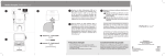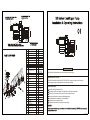
1
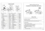
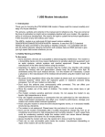
Description
Key NO.
29
28
1
27
Qty
1
Lid lock ring
1
CP-01-02
2
Lid
1
CP-01-03
3
O'ring
1
CP-01W-01
4
Stop back valve
1
CP-01-12
5
Basket
1
CP-01-04
6
Hair with lint pot
1
CP-01-05
7
O'ring bulkhead
4
CP-01W-04
8
Bulkhead fitting
2
MPV-02-005
9
Adaptor bulkhead
2
MPV-02-007
10
Nut bulkhead
2
11
Drain plug with o'ring
1
MPV-02-006
CP-01-013
CP-01W-05
12
Gasket
1
13
Nut
2
CP-02W-03-2
14
Screw
4
CP-01W-08
15
1HP,1.5HP
Base
2HP,3HP
1
CP-01-06-2
CP-01-06-1
16
Pump body
1
CP-01-07
26
2
22
3
4
18
19
20
23
24
25
21
17
30
5
16
6
7
8
9
31
10
14
11
12
13
15
Part No
CP-01W-06
17
O'ring
1
CP-01W-10
18
Diffuser
1
CP-01-08
19
Screw with o'ring
1
CP-01-10
CP-01W-05
20
Impeller
1
CP-01-09
21
Shaft seal
1
CP-01W-13
22
O'ring
1
CP-01W-14
CP-01-11
23
Flange
1
24
Screw
4
CP-01W-16
25
Screw
16
CP-01W-17
27
1HP,1.5HP O'ring
2HP,3HP
Over load switch
28
Irdome
26
30
1HP,1.5HP
Cover
2HP, 3HP
Motor
31
Opening key
29
1
1
1
1
1
CP-01W-18-1
CP-01W-18-2
CP-01W-19
CP-01-14
CP-01-13-2
CP-01-13-1
CP-01W-31
CP-01-00
INSTALLATION
Only qualified, licensed personnel should install pump and wiring.
IMPORTANT ELECTRICAL
Electrical Contractors Please Note: All 220 volt 50 Hz pumps must be wired to the main
power supply through an approved and correctly rated contactor.
Pump Mount Must:
Be solid Level Rigid Vibration Free.
Allow pump suction inlet height to be as close to water level as possible.
Allow use of short, direct suction pipe (To reduce friction losses.)
Allow for gate valves in suction and discharge piping.
Have adequate floor drainage to prevent flooding.
Be protected from excess moisture.
All adequate access for servicing pump and piping.
NOTICE:
Pump suction and discharge connections have moulded in thread stops, DO NOT try to screw pipe
in beyond these stops.
EMPU05080302
OPERATION
!
!
!
!
Hazardous suction.
Can trap hair or
body part, causing
severe injury or
death.
Do not block
suction.
NEVER run pump dry! Running pump dry may damage seals,
causing leakage and flooding! Fill pump with water before
starting motor.
Before removing lid:
STOP PUMP before proceeding.
CLOSE GATE VALVES in suction and discharge pipes.
RELEASE ALL PRESSURE from pump and piping system.
NEVER tighten or loosen screws while pump is operation.
Do not block pump suction! To do so with body may cause severe or fatal
injury. Children using pool must ALWAYS have close adult
Supervision!
Priming Pump:
Release all air from filter and piping system: see filter owner
manual.
In a flooded suction system (water source higher than pump),
pump will prime itself when suction and discharge valves are
opened.
If pump is not in a flooded suction system, unscrew and remove
trap cover; fill trap and pump with water.
Clean and inspect Ring; re-install on trap cover.
Replace trap cover on trap; turn clockwise to tighten cover.
NOTICE: Tighten trap cover by hand only.
Pump should prime now. Priming time will depend on vertical
length of suction lift and horizontal length of suction piping.
Routine Maintenance
The only routine maintenance needed is inspection/cleaning of trap basket. Debris or trash that
collects in basket, will choke off water flow through the pump. Follow instructions below to clean trap:
1.Stop pump, close gate valve in suction and discharge, and release all pressure from system before
proceeding.
2.Unscrew trap lid (turn counterclockwise).
3.Remove strainer basket and clean. Be sure all holes in basket are clear,flush basket with water and
replace in trap with large opening at pipe connection port (between ribs provided). If basket is
replaced backwards cover will not fit on trap body.
4.Clean and inspect lid Ring; reinstall on trap cover.
5.Clean Ring groove on trap body and Replace lid. To help keep lid from sticking, tighten hand tight
only.
6.Prime pump (see priming instructions above)
SERVICE & REPAIR PARTS
Refer all service to your local agent or dealer as his knowledge of your equipment makes
him the vest qualified source of information. Order all repair parts through your dealer. Give
the following information when ordering repair parts:
1. Unit nameplate data or serial number on label.
2. Description of part.
TROUBLE SHOOTING
MOTOR DOES NOT START
1. Disconnect switch or circuit breaker in
off position
2. Fuses blown or thermal overload open
3. Locked motor shaft
4. Motor windings burned out
5. Defective starting switch inside singl
phase motor
6. Disconnected or defective wiring
7. Low voltage
PUMP DOES NOT REACH FULL SPEED
1. Low voltage
2. Pump connected for wrong voltage
MOTOR OVERHEATS (protector trips)
1. Low voltage
2. Motor windings connected for wrong
voltage on dual voltage model
3. Inadequate ventilation
PUMP DELIVERS NO WATER
1. Pump is not primed
2. Closed valve in suction or discharge
line
3. Leakage or air into suction system
4. Impeller clogged
LEAKAGE OF WATER AT SHAFT
1. Shaft seal requires replacement
LOW PUMP CAPACITY
1. Valve in suction or discharge line partly
closed
2. Suction or discharge line partly plugged
3. Suction or discharge line too small
4. Plugged basket in skimmer or hair and
lint strainer
5. Dirty filter
6. Impeller clogged
HIGH PUMP PRESSURE
1. Discharge valve or inlet fittings closed
too much
2. Return lines too small
3. Dirty filters
NOISY PUMP AND MOTOR
1. Plugged basket in skimmer or hair in lint
strainer
2. Worn motor bearings
3. Valve in suction line partly closed
4. Suction line partly plugged
5. Vacuum hose plugged or too small
6. Pump not supported properly
AIR BUBBLES AT INLET FITTINGS
1. Leakage of air into suction line at
connections or valve stem
2. Cover gasket of hair and lint strainer
needs cleaning
3. Low water level in pool
NOTE: If the recommendations in the trouble shooting portion of this manual do not
solve your particular problem(s), please contact your local dealer for service.