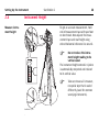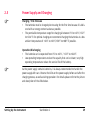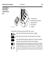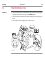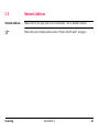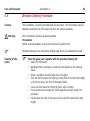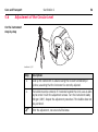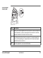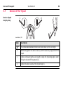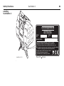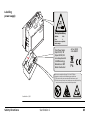
1
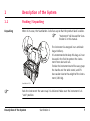
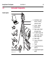
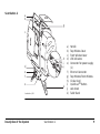
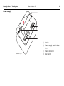
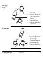
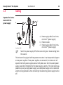
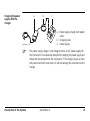
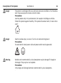
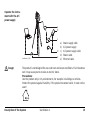
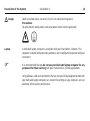
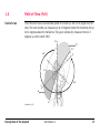
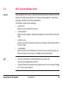
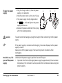
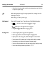
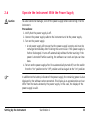
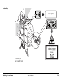
Leica ScanStation 2 User Manual Version 1.0 English ScanStation 2 Introduction 2 Introduction Purchase Congratulations on the purchase of a ScanStation 2 instrument. This manual contains important safety directions as well as instructions for setting up the product and operating it. Refer to "6 Safety Directions" for further information. Read carefully through the User Manual before you switch on the product. Product identification The type and the serial number of your product are indicated on the type plate. Enter the model and serial number in your manual and always refer to this information when you need to contact your agency or Leica Geosystems authorized service workshop. Type: _______________ Serial No.: _______________ Network Address: _______________ IP Address: _______________ Symbols The symbols used in this manual have the following meanings: Type Warning Danger Caution ) Trademarks Introduction Description Indicates an imminently hazardous situation which, if not avoided, will result in death or serious injury. Indicates a potentially hazardous situation or an unintended use which, if not avoided, could result in death or serious injury. Indicates a potentially hazardous situation or an unintended use which, if not avoided, may result in minor or moderate injury and/or appreciable material, financial and environmental damage. Important paragraphs which must be adhered to in practice as they enable the product to be used in a technically correct and efficient manner. • Windows is a registered trademark of Microsoft Corporation All other trademarks are the property of their respective owners. ScanStation 2 3 ScanStation 2 Table of Contents 4 Table of Contents In this manual Chapter 1 Description of the System 1.1 1.2 1.3 1.4 1.5 2 Page Packing / Unpacking Instrument Components Cabling Field of View (FoV) HDS Cyclone Software Suite 7 7 8 12 17 19 Setting Up the Instrument 22 2.1 2.2 2.3 2.4 2.5 2.6 22 23 25 28 29 33 General Information Scanner Setup on Tripod Setup the ScanStation 2 Over a Benchmark Instrument Height Power Supply and Charging Operate the Instrument With the Power Supply 3 4 5 Table of Contents Scanning 34 3.1 3.2 3.3 3.4 3.5 34 36 38 40 41 Turn On the System Understand the Instrument’s Control LED Status Ambient Conditions Reinstalling Window Covers Network Address Troubleshooting 42 4.1 4.2 42 46 Network Connection Diagnostic Procedure Care and Transport 50 5.1 5.2 5.3 5.4 5.5 5.6 5.7 50 51 52 53 54 56 58 Check & Adjust Transport Storage Cleaning and Drying Window Cleaning Procedure Adjustment of the Circular Level Service of the Tripod ScanStation 2 5 ScanStation 2 Table of Contents 6 7 6 Safety Directions 59 6.1 6.2 6.3 6.4 6.5 6.6 6.7 6.8 6.9 59 60 62 63 64 66 75 81 83 General Intended Use Limits of Use Responsibilities International Warranty, Software Licence Agreement Hazards of Use Laser Classification Scanner, Visible Laser Electromagnetic Compatibility EMC FCC Statement, Applicable in U.S. Technical Data 86 7.1 7.2 7.3 7.4 7.5 7.6 7.7 7.8 86 87 88 90 91 92 93 97 Index General Technical Data of the Instrument System Performance Laser Scanning System Electrical Environmental Physical Accessories Formats 98 1 Description of the System 1.1 Packing / Unpacking Unpacking When in its case, the ScanStation 2 sits face-up so that the product label is visible. ) "Instrument" will be used for ScanStation 2 in this manual. The instrument is wrapped in an antistatic bag at delivery. It is recommended to keep this bag, as it can be used in the field to protect the instrument from dust and rain. To take the instrument out of its case, grasp the handle and the table stand, and lift. Use caution due to the weight of the instrument (18.8 kg). ScanStation 2 001 ) Pack the instrument the same way it is delivered. Make sure the instrument is in "Lock" position. Description of the System ScanStation 2 7 1.2 Overall system 8 ScanStation 2 Description of the System Instrument Components a b h i c d j e f 15V 36V 4.0A g ScanStation 2_002 k a) ScanStation 2 Laser Scanner; including protective covers b) Laptop - optional c) Ethernet cable d) Power supply charger with power cable e) A/C power supply with power cable - optional f) Power supply cable g) Power supply h) Tribrach, with optical plummet i) Tripod j) Transport box for ScanStation 2 k) Transport box for power supply ScanStation 2 a b g c h i j d e f e k ScanStation 2_003 Description of the System ScanStation 2 a) b) c) d) e) Handle Top Window Cover Front Window Cover LED indicators Connector for power supply (2) f) Ethernet Connector g) Top Window/Front Window h) Circular level i) QuickScanTM Button j) Lock Knob k) Table Stand 9 10 ScanStation 2 Description of the System Power supply a 15 V b c 36 V 4.0 A d ScanStation 2_004 a) Handle b) Power supply status indicators c) Power connector d) Main switch Power supply charger a b c d ScanStation 2_005 A/C power supply a) Charger cable b) Control LED; lights when the charger is connected to a power plug. c) Power supply charger d) Power cable; three different types delivered a b c d ScanStation 2_026 Description of the System ScanStation 2 a) A/C power supply b) Control LED; lights when the A/C power supply is connected to a power plug. c) A/C power supply cable d) Power cable; three different types delivered 11 12 ScanStation 2 Description of the System 1.3 Cabling Operate the instrument with the power supply a c 15V 36V 4.0A 15V b 36V 4.0A ScanStation 2_006 ) a) Power supply cable (from instrument to 1st power supply) b) Ethernet cable c) Power supply cable (from instrument to 2nd power supply) Switch the power supply OFF before connecting to or disconnecting from the scanner. The instrument is equipped with two power connectors. It can be operated using one or two power supplies. If two power supplies are connected, the instrument will operate from both power supplies concurrently. Make sure that the second power supply is switched ON before the first power supply is empty. If the instrument was powered up using a single power supply, a second power supply can be connected anytime during operation. when connecting or disconnecting, power supply must be off. Charging the power supply with the charger a b c 15V 36V 4.0 A ScanStation 2_007 ) Description of the System a) Power supply charger with power cable b) Charging cable c) Power supply The power supply charger is not designed to be an A/C power supply for the instrument. It is exclusively designed for charging the power supply and should not be connected to the instrument. If the charger plug is accidentally connected to the instrument, it will not damage the instrument or the charger. ScanStation 2 13 Description of the System Danger Danger Warning ScanStation 2 14 The product is not designed for use under wet and severe conditions. If unit becomes wet it may cause you to receive an electric shock. Precautions: Use the product only in dry environments, for example in buildings or vehicles. Protect the product against humidity. If the product becomes humid, it must not be used! Death or serious injury can occur if unit is not connected to ground. Precautions: To avoid electric shock power cable and power outlet must be grounded. Batteries not recommended by Leica Geosystems may be damaged if charged or discharged. They may burn and explode. Precautions: Only charge and discharge batteries recommended by Leica Geosystems. Operate the instrument with the A/C power supply a b c d e ScanStation 2_008 Danger a) b) c) d) e) Power supply cable A/C power supply A/C power supply cable Power cable Ethernet cable The product is not designed for use under wet and severe conditions. If unit becomes wet it may cause you to receive an electric shock. Precautions: Use the product only in dry environments, for example in buildings or vehicles. Protect the product against humidity. If the product becomes humid, it must not be used! Description of the System ScanStation 2 15 Description of the System Danger Laptop ) ScanStation 2 16 Death or serious injury can occur if unit is not connected to ground. Precautions: To avoid electric shock power cable and power outlet must be grounded. A dedicated laptop computer is an option with your ScanStation 2 System. This computer is loaded with proprietary software, and is configured to operate with your instrument. It is recommended that you do not use your dedicated laptop computer for any purpose other than scanning with your instrument or Cyclone applications. Using software, LAN cards or modems that are not specifically designed to work with your dedicated laptop computer can corrupt the settings in your computer, and can adversely affect system performance. 1.4 Field of View (FoV) Field of view The instrument has a dual window system that covers a 360 x 270 degree field of view. The main window (a) measures up to 45 degrees below the horizontal and up to 32 degrees above the horizontal. The upper window (b) measures from 22.5 degrees up to the zenith (90°). 90° b 22.5° 360° 0° 32° 360° 0° a 45° ScanStation 2_009 Description of the System ScanStation 2 17 Description of the System ScanStation 2 18 If selecting a scanning region that uses both the main and upper windows, the instrument automatically goes through the following steps (as an example a vertical extent of -20 to 50 degrees): 1. The instrument starts scanning using the main window and scans from -20 to 32 degrees. 2. It then makes a 180 degrees horizontal rotation. 3. It finishes the scan (32 to 50 degrees) using the upper window. 1.5 HDS Cyclone Software Suite General Leica Geosystems HDS Cyclone - software modules provide point cloud users with the widest set of work process options for 3D laser scanning projects in engineering, surveying, construction and related applications. The Software consist of four packages: • Cyclone-Scan: allows the user to control the Scanner • Cyclone-Register: allows the user to register multiple Scans together or to Geo-reference the point cloud • Cyclone-Survey: gives the user basic functionality to extract and measure information out of the rich point cloud • Cyclone-Model: gives the user the full functionality of Cyclone. The user is able to extract and measure features and to create a 3D Model out of the PointCloud ) • • For more information on Cyclone Software Suite, please visit: http://www.leica-geosystems.com/hds Cyclone Software has also online help available, which can be accessed through the F1 key on your keyboard. Description of the System ScanStation 2 19 ScanStation 2 Description of the System General Operating Principles • 20 Download: Cyclone Software, as well as important Support documentation, can be down- • loaded from the Leica Geosystems HDS Website (http://www.leica-geosystems.com/hds/en/lgs_27054.htm). The User must create an account before the download section is accessible. Installation: You must use a Windows account with administrator privileges to install or upgrade Cyclone, CloudWorx for AutoCAD, or CloudWorx for Intergraph SmartPlant® Review. ) Windows 2000 users: If Cyclone, CloudWorx for AutoCAD, or CloudWorx for Intergraph SmartPlant® Review fails to launch with an "entry point HeapSetInformation" error message after installing or upgrading, A) install Windows 2000 Service Pack 3 or Service Pack 4 with all available security updates (recommended), or B) install the Microsoft hotfix for KB816542 (download and unzip the file, then run "Windows2000-KB816542-x86-ENU.exe" to install the hotfix). 1. Download the Cyclone Installshield from the website specified above. 2. Run the Installation file. 3. Follow the onscreen instructions and select the software you wish to install. 4. Go to the License Request Page • Language: Cyclone's operating Language is English. Description of the System ScanStation 2 21 Setting Up the Instrument ScanStation 2 22 2 Setting Up the Instrument 2.1 General Information Use the tripod The instrument should always be set up on its tripod. Using the tripod delivered with the scanning system guarantees a maximum of stability during scanning operations. ) ) Always set up the instrument on its tripod. Do not set up the instrument directly on the ground for scanning operations. Never operate the scanner using the table stand. It is always recommended to shield the instrument from direct sunlight and avoid uneven temperatures around the instrument. 2.2 Scanner Setup on Tripod Setup step-by-step 6 2 5 2 4 4 1 1 3 3 4 1 3 ScanStation 2_010 Step ) Setting Up the Instrument Description Shield the instrument from direct sunlight and avoid uneven temperatures around the instrument. ScanStation 2 23 ScanStation 2 Setting Up the Instrument Step 24 Description 1. Extend the tripod legs to allow for a comfortable working posture. Tighten the screws at the bottom of the legs. 2. Place the tribrach on the tripod and secure it with the central fixing screw. 3. Set up the tripod so that the tripod plate is as horizontal as possible. 4. Push the tripod legs firmly into the ground. 5. Level up the tribrach using the circular level. Turn two of the foot screws together in opposite directions. The index finger of your right hand indicates the direction in which the bubble should move. Now use the third foot screw to centre the bubble. 6. Place the instrument on the tribrach and secure it with the tribrach’s locking knob. Make sure that the instrument is levelled by checking the built-in circular level. ) ) The instrument must be levelled before it is switched ON. If not levelled using the tribrach’s or the instrument’s circular level, it may not power up properly or scanning accuracy may not be achieved. When placing the instrument on the tribrach, align the legs of the scanner’s table stand with the foot screws of the tribrach. 2.3 Setup the ScanStation 2 Over a Benchmark Description Geo-referencing of the ScanStation 2 is established by setting up over a known or assumed control point, with optional target extraction to set the azimuth direction, and establishing a local or global coordinate system. ScanStation 2 allows you to traverse, resection or free-station. Known azimuth or known backsight measurements can be observed. ) ) It is always possible to set up the instrument without the need for a marked ground point. The data scanned with ScanStation 2 is corrected by an internal dual-axis compensator, when the dual-axis compensator is enabled (by Cyclone). Setting Up the Instrument ScanStation 2 25 26 ScanStation 2 Setting Up the Instrument Setup step-by-step 7 6 2 3 5 2 5 6 6 1 1 4 1 4 6 5 4 ScanStation 2_011 Step ) Description Shield the instrument from direct sunlight and avoid uneven temperatures around the instrument. 1. Extend the tripod legs to allow for a comfortable working posture. Position the tripod approximately over the marked ground point. 2. Fasten the tribrach onto the tripod. Step Description 3. Inspect the tripod from various sides and correct its position so that the tripod plate is roughly horizontal and above the ground point. You may use the tribrach’s optical plummet to help place the tripod over the ground point. 4. Push the tripod legs firmly into the ground. 5. Look through the optical plummet and turn the tribrach’s foot screws so that the optical plummet is centered on the ground point. 6. Adjust the tripod legs to level the circular level. 7. Place the instrument on the tribrach and secure it with the tribrach’s locking knob. Make sure that the instrument is levelled by checking the built-in circular level. ) Setting Up the Instrument Please see also "Scanning with ScanStation 2" section in the Cyclone documentation for more information. ScanStation 2 27 2.4 28 ScanStation 2 Setting Up the Instrument Instrument Height To get an accurate measurement, hold end of measurement tape with your foot on benchmark. Now expand the measurement tape and read height using etched horizontal reference line on unit. Measure instrument height 149 150 151 152 153 ) ScanStation 2_012 Do not reduce the instrument height reading to its vertical value! The instrument height entered in Cyclone is automatically computed and reduced to its vertical value. ) Take care to use a 1:1 measure, no special tape that is scaled differently (used for common surveying instruments). 2.5 ) Power Supply and Charging Charging / first-time use • The batteries must be charged prior to using for the first time because it is delivered with an energy content as low as possible. • The permissible temperature range for charging is between 0°C to +40°C /+32°F to +104°F. For optimal charging we recommend charging the batteries at a low ambient temperature of +10°C to +20°C/+50°F to +68°F if possible. Operation/Discharging • The batteries can be operated from 0°C to +40°C / +32°F to +104°F. • Low operating temperatures reduce the capacity that can be drawn; very high operating temperatures reduce the service life of the battery. ) As the power supply contains batteries, it is always recommended to handle the power supply with care. Observe the LEDs on the power supply before and after the charging process, as well as during operation. For details please refer to the picture and description of the LEDs below. Setting Up the Instrument ScanStation 2 29 30 ScanStation 2 Setting Up the Instrument Understand the power supply condition indicators a b c d e 15V 36V 4.0 A ScanStation 2_013 a) b) c) d) e) Low power level Power supply is half empty High power level Fully charged Charging If the battery is turned on and not connected to the scanner: Amber color indicates that the power supply is charging. Amber color switches on when the power supply is fully charged. Green color indicates high power supply level. It stays on for approximately one hour and twenty minutes at room temperature. Yellow color switches on when power supply is half empty. It stays on for approximately one hour and twenty minutes at room temperature. Red color indicates low power level. When it switches on, approximately twenty minutes of operation are left before the instrument is powered off. Charge the power supply 1. Plug the charger cable (b) into the power supply’s (c) connector. 2. Plug the power cable (a) into an A/C plug. 3. The power supply is fully charged when a b c 15V the indicator light on the power supply switches on. 4. Remove the power cable from the A/C plug after the charging process. Caution ) Period of use, life span of the power supply 36V 4.0 A ScanStation 2_014 To avoid connector damage, unplug the charger before connecting it to the power supply. If the power supply is turned on while charging, the status displayed at the power supply is invalid. Always turn off the power supply if not used to prevent its batteries from discharging. Understand the power supply‘s period of use and life span: • Operation time for a fully charged power supply is approximately 3 hours at room temperature. The instrument can be operated for 6 continuous hours using two power supplies. Setting Up the Instrument ScanStation 2 31 Setting Up the Instrument • ) Notify support 32 After 200 to 300 cycles, consider contacting Leica Geosystems or your distributor to replace the power supply. Before storing the power supply for a longer period of time, recharge it to avoid shortening the life span. Before storage, turn off the power supply. Please notify the support team, if you notice any of the following behaviours: • Handling advice ScanStation 2 LED does not turn off after unplugging the charger. • • LED stays on after eight hours of charging time. The power supply is hot after the charging process. • • • • • • • Do not charge the power supply more than eight hours. Power supply needs to be turned off during the charging process. Properly remove the wall plug first, before removing the Lemo connector. Do not tamper with the power supply or charger during charging or usage. Do not obstruct vent holes on the bottom of the power supply. Do not put flammable objects near the power supply during charging or usage. Do not store discharged power supply below 0° C/32° F. 2.6 Caution ) Operate the Instrument With the Power Supply To avoid connector damage, turn off the power supply before connecting it to the instrument. Precautions: 1. Verify that the power supply is off. 2. Connect the power supply cable to the instrument and to the power supply. 3. Turn on the power supply. • A red power supply LED means that the power supply is empty and must be recharged immediately after finishing the current scan. If the power supply is further discharged, it turns off automatically without further warning. If the power is turned off while scanning, the software can crash and you can lose data. 4. To turn on the power supply after it has automatically turned off, turn the switch from the "On" position to the "Off" position and back again to the "On" position. In addition to the battery indicator of the power supply, the remaining power is also displayed by the software when connected. This display is an approximation and can differ from the status shown by the power supply. In this case, the display of the power supply is valid. Setting Up the Instrument ScanStation 2 33 ScanStation 2 Scanning 3 Scanning 3.1 Turn On the System System Start up ) 34 1. Set up the instrument as desired. Refer to chapter "2 Setting Up the Instrument" for more infomation. 2. Turn on the laptop computer. 3. Connect all cables to the instrument as described earlier. Refer to chapter "1.3 Cabling" for more infomation. 4. Remove the window covers from the instrument. The window covers can be hooked up on the tripod or placed in the instrument’s case. 5. Unlock the instrument by pulling the black knob on the back and turning it to its “UNLOCKED” position. The instrument must be in the UNLOCKED position for power-up (see picture on page 36). Otherwise Cyclone will continue to try to connect while the instrument does not start up correctly. Note that the instrument is rotating freely when in UNLOCKED position and powered OFF. 6. Switch on the power supplies or connect the A/C power supply. Refer to chapter "1.3 Cabling" for more information. 7. The RDY yellow light (see picture on page 36) should be flashing while the instrument is getting ready for scanning. ) Scanning The power-up process requires approximately five minutes to complete. During the power-up process, you will see the scanner rotate and the mirror behind the scanner main window will spin. 8. The instrument is ready when the RDY light is green. Note that it is no longer in the free rotational mode when powered up. The instrument should never be touched while powering up or when ready. It should not be touched during operation with the exception of the QuickScan operation. Refer to the QuickScan section of the Cyclone documentation for further details. 9. To connect the instrument to Cyclone software and begin scanning operations, refer to the Cyclone documentation for further information. 10. Start Cyclone. ScanStation 2 35 3.2 36 ScanStation 2 Scanning Understand the Instrument’s Control LED Status Diagram RD YC NE ScanStation 2_015 RDY OM a b c LS R POWER TW OR K a) RDY LED b) COM LED c) LSR LED Flashing yellow color indicates that the instrument is powering up. Green color indicates that the instrument is ready for scanning. If the flashing yellow light appears while the instrument is scanning or waiting for a command, it indicates that it is performing a self-accuracy adjustment. This procedure takes approximately two minutes. If the instrument is scanning when self-accuracy adjustment starts, scanning will be interrupted for approximately two minutes and then automatically restart. COM Flashing green color indicates that the instrument is communicating with Cyclone. Red color indicates a scanner failure. Please refer to chapter "Diagnostic Procedure" for further instructions if this happens. LSR Orange color indicates that the laser is ON. The LSR light is always orange once the scanner completes the power up process. Scanning ScanStation 2 37 ScanStation 2 Scanning 3.3 Ambient Conditions Unfavorable surfaces • • • Unfavourable weather conditions Highly reflective (polished metal, gloss paint) Highly absorbent (black) Translucent (clear glass) ) ) Color or powder these surfaces before scanning if necessary. • • Temperature changes 38 ) • Rain, snow or fog cause poor measurements. It is not recommended to survey during these conditions! If some objects are scanned against the sunlight or a bright spotlight, the optical receiver of the instrument can be dazzled so heavily that in this area no measured data is recorded. A "black hole" appears in the reflectance image. If the instrument is brought from a cold environment (e.g., from storage) into a warm and humid environment, the glass window at the mirror or in extreme case even the interior optics can fog up. This causes measurement errors. Precaution: Avoid large temperature differences; give the instrument time to acclimate. Window Glass Laptop computer ) ) Soiling at the glass, such as a layer of dust, condensed water or fingerprints, causes considerable measuring errors. • • • Others Cyclone-SCAN ) Keep field notes containing: • Target positions relative to the instrument. • Position of the instrument within the measured area. The Cyclone-SCAN software controls scanning operations with the instrument and allows point cloud visualization and measurement. ) Scanning Retain enough fee disk space, depending on your Project, up to 50% of your hard drive. Do not additionally stress the computer while scanning. It is not recommended to perform other Cyclone tasks while Scanning. • Refer to the Cyclone help system for information about the connection of the instrument to Cyclone and further scanning operations. ScanStation 2 39 3.4 Procedure 40 ScanStation 2 Scanning Reinstalling Window Covers 1. Ensure that the instrument is switched off and lock the instrument by pulling the black knob on the back and turning it to its LOCKED position. 2. Check the back of the window covers before reinstalling to assure proper orientation. 3. Push window cover with a light pressure to lock it in place. 3 2 2 Front Window This way UP Top Window This way UP 3 1 ScanStation 2_016 3.5 Network Address Network address Please refer to the type plate on the ScanStation 2 for its Network address. ) Please note your network address under "Product identification" on page 2. Scanning ScanStation 2 41 ScanStation 2 Troubleshooting 4 Troubleshooting 4.1 Network Connection 42 Physical problems 1. Is one end of the ethernet cable securely attached to the connector labeled NETWORK on the instrument base? 2. Is the other end of the ethernet cable securely attached to the laptop? 3. Is the COM indicator light on the instrument base lit? This indicates that the instrument networking module has power. 4. Are you using the correct network cable? You can tell by holding the two modular connectors side-by-side. The colored wires inside the two modular connectors should be in the same order if the cable is directly connecting the instrument to the laptop. Software configuration problems 1. 2. 3. 4. Start Cyclone. Start the Scan Control viewer for your scanner. Initiate connection to the instrument. If the progress bar remains at 10%, then Cyclone cannot locate the scanner on the network. • Check that your laptop network settings are correct. Check IP address, LAN properties, internet protocol (TCP/IP) properties: IP address: refer to chapter "3.5 Network Address" Subnet mask: 255.255.0.0 Default gateway: 10.1.1.1 • If your network settings are correct, check if you have a wireless network enabled. An active wireless network may disrupt the connection between Cyclone and the instrument. 5. If the progress bar remains at 40% or 70%, then Cyclone is able to locate the instrument on the network but is unable to complete the connection protocol. • If the instrument is initializing or performing its periodic accuracy checking, Cyclone may not be able to connect until the scanner is ready. This is normal. Refer to chapter "3.2 Understand the Instrument’s Control LED Status" for more information. • If Cyclone has not successfully connected within ten minutes: a) Cancel the connection. b) Exit Cyclone. c) Confirm that Cyclone is not running by looking for Cyclone.exe in the Task Manager's Processes tab. If it is continuing to run, select the Cyclone.exe process and push the End Process button. d) Restart Cyclone and try to connect once more. e) If the second attempt fails, reboot the instrument. f) If the third attempt fails, reboot the laptop computer and the Scanner, then attempt to connect to the instrument. 6. If connection to the instrument still fails, initiate the diagnostic procedure described in chapter "4.2 Diagnostic Procedure". Troubleshooting ScanStation 2 43 Troubleshooting Configuration of wireless network adapter ScanStation 2 44 Laptops delivered by Leica Geosystems together with a laser scanning system have a built-in wireless network adapter. You may enable/disable the wireless network adapter by following the next steps: 1. Open Network Connections. 2. Right-click Wireless Network Connection, and then click Properties. 3. Select the Wireless Networks tab. 4. To enable automatic wireless network configuration, select the Use Windows to configure my wireless network settings check box; or to disable automatic wireless network configuration, clear the Use Windows to configure my wireless network settings check box. Troubleshooting ScanStation 2 45 Troubleshooting ScanStation 2 46 4.2 Diagnostic Procedure Diagnostic procedure The diagnostic procedure explains how to create diagnostic reports in case of problems with the scanner and/or the connection. To create diagnostic reports, follow the steps described below: 1. Connect the ethernet cable to the instrument and the laptop. 2. Start Cyclone and open a Scan Control window (see Cyclone on-line help). 3. Switch on the instrument. 4. Connect to the instrument from the Cyclone Scan Control window. Diagnostic information is stored in a text file as soon as you try to connect. A new diagnostic file is created for each new connection in the following folder on your laptop: …\Leica Geosystems\Cyclone\Databases\temp Example file name: Diag_10.1.194.114_2004.03.04.11.45.txt Verify the network address If you cannot connect to the instrument after booting up and diagnostic reports are not created, check the network address of the instrument. To verify the network address, try to ping the instrument. 1. Open the DOS window: From the Windows desktop, click the Start button, and then point to Programs and click MS DOS Prompt. The DOS window appears. 2. At the cursor, type ping 10.1.194.X (10.1.194.X is the instrument's network address) and press ENTER. The ping process begins. DOS window illustrating an unsuccessful ping procedure: "Request timed out" is one of several possible responses indicating failure of the ping procedure. DOS window illustrating a successful ping procedure: Troubleshooting ScanStation 2 47 Troubleshooting ScanStation 2 48 3. If the ping procedure fails, and you have verified that you are using a properly connected ethernet cable, the cable may be broken. • Turn the power switch OFF, and replace the ethernet cable (make sure to use a standard ethernet cable). • Turn the instrument "ON." • If the ping procedure still fails, contact Leica HDS Technical Support. In case of problems If you experience one of the following problems with the scanner and/or the scanner connection: • If the instrument does not boot up: Switch off the instrument and switch it on again. Try to connect to the instrument from the Scan Control window. Diagnostic reports are stored every time you attempt to connect to the scanner. • If the instrument boots up and the RDY light is on, but connection is not possible: Try to ping the instrument (see ping procedure above). • If there is no diagnostic report, check the network address of the instrument and the network settings on your laptop. • If you experience problems while scanning, or taking images, Email a copy of the diagnostic report to Leica HDS Technical Support. • If the COM light is red: Reboot the instrument. If the light is still red, contact Leica HDS Technical Support. Summary If you experience problems with your instrument: • Email the scanner's diagnostic reports to your local support: • Email address: [email protected] • For Europe support: [email protected] • Troubleshooting Diagnostic reports are stored in the following folder: • …\Leica Geosystems\Cyclone\Databases\temp • Example file name: Diag_10.1.194.114_2004.03.04.11.45.txt ScanStation 2 49 ScanStation 2 Care and Transport 5 Care and Transport 5.1 Check & Adjust Caution 50 Units that are exposed to high mechanical forces, e.g. through frequent transport or rough handling, it is recommended to carry out a check and adjust once a year by the manufacturer respectively just after such a high stress exposure. 5.2 Transport Transport in the field When transporting the equipment in the field, always make sure that you • either carry the product in its original transport container, • remove product from tripod and carry by its handle. Transport in a road vehicle Never carry the product loose in a road vehicle, as it can be affected by shock and vibration. Always carry the product in its transport container and secure it. Shipping When transporting the product by rail, air or sea, always use the complete original Leica Geosystems packaging, transport container and cardboard box, or its equivalent, to protect against shock and vibration. Shipping, transport of batteries When transporting or shipping batteries, the person in charge of the product must ensure that the applicable national and international rules and regulations are observed. Before transportation or shipping, contact your local passenger or freight transport company. Care and Transport ScanStation 2 51 ScanStation 2 Care and Transport 52 5.3 Storage Product Respect the temperature limits when storing the equipment, particularly in summer if the equipment is inside a vehicle. Refer to "7 Technical Data" for information about temperature limits. Field adjustment After long periods of storage, inspect the field adjustment parameters given in this user manual before using the product. Batteries • • • • • • Refer to "7.5 Environmental" for information about storage temperature range. A storage temperature range of -20°C to +30°C/-4°F to 86°F in a dry environment is recommended to minimize self-discharging of the battery. At the recommended storage temperature range, batteries containing a 10% to 50% charge can be stored for up to one year. After this storage period the batteries must be recharged. Remove batteries from the product and the charger before storing. After storage, recharge batteries before using. Protect batteries from damp and wetness. Wet or damp batteries must be dried before storing or use. 5.4 Cleaning and Drying Windows and targets • • • • • Blow dust off scanner windows. Never touch the glass with your fingers. Use only a clean, soft, lint-free cloth for cleaning. If necessary, moisten the cloth with water or pure alcohol. Do not use other liquids; these may attack the polymer components. Charger: Use only a clean, soft, lint-free cloth for cleaning. Damp products Dry the product, the transport container, the foam inserts and the accessories at a temperature not greater than 40°C / 104°F and clean them. Do not repack until everything is completely dry. Cables and plugs Keep plugs clean and dry. Blow away any dirt lodged in the plugs of the connecting cables. Care and Transport ScanStation 2 53 ScanStation 2 Care and Transport 54 5.5 Window Cleaning Procedure General The ScanStation 2 scanning windows shall be kept clean. The instructions must be followed as described in this chapter to clean the scanner windows. Warning ) Cleaning of the optics Direct intrabeam viewing is always hazardous. Precautions: Before cleaning windows, ensure the instrument is switched off. Window Cleaning Kit can be ordered through your local Leica Geosystems dealer. ) Clean the glass pane regularly with the provided cleaning kit: • Switch off instrument. • Washing hands is necessary in order to avoid grease on the cleaning tissue. • Better, use gloves to avoid finger oil on the glass. • Then use the lens tissue for wiping circularly from the center to the edge until there is only a thin film of detergent visible. • Use a new lens tissue for drying the pane, wipe circularly. • If any smears from cleaning are visible against back light, repeat the procedure. • Do not touch the side of the paper that is used for cleaning with your fingers. • • • Care and Transport Do not reuse tissues that have been used before. Only use non-fuzzy lens tissues. Do not use air from the pneumatic power system as this is always slightly oily! ScanStation 2 55 ScanStation 2 Care and Transport 5.6 56 Adjustment of the Circular Level On the instrument step-by-step ScanStation 2_017 Step Description 1. Level up the instrument in advance using the re-level functionality in Cyclone, assuming that the instrument is correctly adjusted. 2. The bubble must be centered. If it extends beyond the circle, use an allen key to center it with the adjustment screws. Turn the instrument slowly 200 gon (180°). Repeat the adjustment procedure if the bubble does not stay centered. ) After the adjustment, no screw shall be loose. On the tribrach step-by-step ScanStation 2_018 Step Level up the tribrach together with the instrument in advance using the relevel funtionality in Cyclone, assuming that the instrument is correctly adjusted. Remove the instrument from the tribrach. 2. The bubble of the tribrach must be centered. If it extends beyond the circle, use the adjusting pin in conjunction with the two cross-headed adjustment screws to centre it. ) Care and Transport Description 1. After the adjustment, no screw shall be loose. ScanStation 2 57 5.7 58 ScanStation 2 Care and Transport Service of the Tripod Service tripod step-by-step 2 1 3 ScanStation 2_019 Step ) Description The connections between timber and metal must be firm and tight. 1. Moderately tighten the allen screws (1) with the allen key supplied with the tripod. 2. Tighten articulated joints just enough to keep the tripod legs open when lifting the tripod off the ground (2). 3. Tighten the allen screws of the tripod legs (3). 6 Safety Directions 6.1 General Description The following directions should enable the person responsible for the product, and the person who actually uses the equipment, to anticipate and avoid operational hazards. The person responsible for the product must ensure that all users understand these directions and adhere to them. Safety Directions ScanStation 2 59 ScanStation 2 Safety Directions 60 6.2 Intended Use Permitted use • • • • • • • • Measuring horizontal and vertical angles. Measuring distances. Recording measurements. Computing by means of software. Target search, recognition. Visualizing the aiming direction and vertical axis. Remote control of surveying products. Data communication with external appliances. Adverse use • • • • • Use of the product without instruction. Use outside of the intended limits. Disabling safety systems. Removal of hazard notices. Opening the product using tools, for example screwdriver, unless this is specifically permitted for certain functions. Modification or conversion of the product. Use after misappropriation. Use of products with obviously recognizable damages or defects. Use with accessories from other manufacturers without the prior explicit approval of Leica Geosystems. • • • • • • • Warning Safety Directions Inadequate safeguards at the surveying site, for example when measuring on roads. Deliberate dazzling of third parties. Controlling of machines, moving objects or similar monitoring application without additional control- and safety installations. Adverse use can lead to injury, malfunction and damage. It is the task of the person responsible for the equipment to inform the user about hazards and how to counteract them. The product is not to be operated until the user has been instructed on how to work with it. ScanStation 2 61 ScanStation 2 Safety Directions 62 6.3 Limits of Use Environment Suitable for use in an atmosphere appropriate for permanent human habitation: not suitable for use in aggressive or explosive environments. Danger Local safety authorities and safety experts must be contacted before working in hazardous areas, or in close proximity to electrical installations or similar situations by the person in charge of the product. 6.4 Responsibilities Manufacturer of the product Leica Geosystems AG, CH-9435 Heerbrugg, hereinafter referred to as Leica Geosystems, is responsible for supplying the product, including the user manual and original accessories, in a completely safe condition. Manufacturers of non Leica Geosystems accessories The manufacturers of non Leica Geosystems accessories for the product are responsible for developing, implementing and communicating safety concepts for their products, and are also responsible for the effectiveness of those safety concepts in combination with the Leica Geosystems product. Person in charge of the product The person in charge of the product has the following duties: • To understand the safety instructions on the product and the instructions in the user manual. • To be familiar with local regulations relating to safety and accident prevention. • To inform Leica Geosystems immediately if the product and the application becomes unsafe. Warning Safety Directions The person responsible for the product must ensure that it is used in accordance with the instructions. This person is also accountable for the training and the deployment of personnel who use the product and for the safety of the equipment in use. ScanStation 2 63 Safety Directions ScanStation 2 64 6.5 International Warranty, Software Licence Agreement International Warranty The International Warranty can be downloaded from the Leica Geosystems home page at http://www.leica-geosystems.com/internationalwarranty or received from your Leica Geosystems dealer. Software Licence Agreement This product contains software that is preinstalled on the product, or that is supplied to you on a data carrier medium, or that can be downloaded by you online pursuant to prior authorization from Leica Geosystems. Such software is protected by copyright and other laws and its use is defined and regulated by the Leica Geosystems Software Licence Agreement, which covers aspects such as, but not limited to, Scope of the Licence, Warranty, Intellectual Property Rights, Limitation of Liability, Exclusion of other Assurances, Governing Law and Place of Jurisdiction. Please make sure, that at any time you fully comply with the terms and conditions of the Leica Geosystems Software Licence Agreement. Such agreement is provided together with all products and can also be found at the Leica Geosystems home page at http://www.leica-geosystems.com/swlicense or your Leica Geosystems dealer. You must not install or use the software unless you have read and accepted the terms and conditions of the Leica Geosystems Software Licence Agreement. Installation or use of the software or any part thereof, is deemed to be an acceptance of all the terms and conditions of such licence agreement. If you do not agree to all or some of the terms of such licence agreement, you may not download, install or use the software and you must return the unused software together with its accompanying documentation and the purchase receipt to the dealer from whom you purchased the product within ten (10) days of purchase to obtain a full refund of the purchase price. Safety Directions ScanStation 2 65 ScanStation 2 Safety Directions 6.6 Warning Caution 66 Hazards of Use The absence of instruction, or the inadequate imparting of instruction, can lead to incorrect or adverse use, and can give rise to accidents with far-reaching human, material, financial and environmental consequences. Precautions: All users must follow the safety directions given by the manufacturer and the directions of the person responsible for the product. Watch out for erroneous measurement results if the product has been dropped or has been misused, modified, stored for long periods or transported. Precautions: Periodically carry out test measurements and perform the field adjustments indicated in the user manual, particularly after the product has been subjected to abnormal use and before and after important measurements. Danger Warning Warning Safety Directions Because of the risk of electrocution, it is very dangerous to use poles and extensions in the vicinity of electrical installations such as power cables or electrical railways. Precautions: Keep at a safe distance from electrical installations. If it is essential to work in this environment, first contact the safety authorities responsible for the electrical installations and follow their instructions. If the product is used with accessories, for example masts, staffs, poles, you may increase the risk of being struck by lightning. Precautions: Do not use the product in a thunderstorm. During dynamic applications, for example stakeout procedures, there is a danger of accidents occurring if the user does not pay attention to the environmental conditions around, for example obstacles, excavations or traffic. Precautions: The person responsible for the product must make all users fully aware of the existing dangers. ScanStation 2 67 Safety Directions Warning Warning Caution Warning ScanStation 2 68 Inadequate securing of the surveying site can lead to dangerous situations, for example in traffic, on building sites, and at industrial installations. Precautions: Always ensure that the survey site is adequately secured. Adhere to the regulations governing safety and accident prevention and road traffic. If computers intended for use indoors are used in the field there is a danger of electric shock. Precautions: Adhere to the instructions given by the computer manufacturer with regard to field use in conjunction with Leica Geosystems products. If the accessories used with the product are not properly secured and the product is subjected to mechanical shock, for example blows or falling, the product may be damaged or people may sustain injury. Precautions: When setting-up the product, make sure that the accessories, for example tripod, tribrach, connecting cables, are correctly adapted, fitted, secured, and locked in position. Avoid subjecting the product to mechanical stress. Only Leica Geosystems authorized service workshops are entitled to repair these products. Warning Danger Warning Warning Safety Directions Using a battery charger not recommended by Leica Geosystems can destroy the batteries. This can cause fire or explosions. Precautions: Only use chargers recommended by Leica Geosystems to charge the batteries. Death or serious injury can occur if unit is not connected to ground. Precautions: To avoid electric shock power cable and power outlet must be grounded. High mechanical stress, high ambient temperatures or immersion into fluids can cause leackage, fire or explosions of the batteries. Precautions: Protect the batteries from mechanical influences and high ambient temperatures. Do not drop or immerse batteries into fluids. Short circuited battery terminals can overheat and cause injury or fire, for example by storing or transporting in pockets if battery terminals come in contact with jewellery, keys, metallized paper or other metals. Precautions: Make sure that the battery terminals do not come into contact with metallic objects. ScanStation 2 69 Safety Directions Caution Caution Warning ScanStation 2 70 Direct rain or water may damage and/or reduced lifetime on the battery. Precautions: During outdoor use keep the battery in an against rain protected place. Long term storage may reduce lifetime or damage the battery. Precautions: During long term storage, maintain battery life by periodic re-charge. During usage, charging and/or disposal one of the following can occur with impact to humans and environment: Explosion hazard: A highly-explosive oxyhydrogen gas mixture occurs when charging batteries. Precautions: Fires, sparks, naked lights and smoking are prohibited: Avoid causing sparks when dealing with cables and electrical equipment, and beware of electrostatic discharges. Avoid short-circuits. Corrosive hazard: Battery acid is highly corrosive. Precautions: Wear protective gloves and eye protection. Do not tilt battery, acid can escape from the degassing openings or vents. Caution Warning Warning Safety Directions During the transport, shipping or disposal of batteries, it is possible for inappropriate mechanical influences to constitute a fire hazard. Precautions: When transporting shipping, or disposing batteries, the person in charge of the product must ensure that the applicable national and international rules and regulations are observed. Before transportation or shipping contact your local passenger or freight transport company. Charging or operating the battery at temperatures below 0°C / +32°F or above +40°C / +104°F is not allowed since it may damage the battery. Precautions: Only charge the battery in well-ventilated areas because it can produce explosive gases. Connect the battery to the battery charger only when the charger is turned off. Fire, smoking, and sparking near the battery are not allowed. If the product is improperly disposed of, the following can happen: • If polymer parts are burnt, poisonous gases are produced which may impair health. ScanStation 2 71 ScanStation 2 Safety Directions 72 • If batteries are damaged or are heated strongly, they can explode and cause poisoning, burning, corrosion or environmental contamination. • By disposing of the product irresponsibly you may enable unauthorized persons to use it in contravention of the regulations, exposing themselves and third parties to the risk of severe injury and rendering the environment liable to contamination. • Improper disposal of silicone oil may cause environmental contamination. Precautions: The product must not be disposed of with household waste. Dispose of the product appropriately in accordance with the national regulations in force in your country. Always prevent access to the product by unauthorized personnel. Product specific treatment and waste management information can be downloaded from the Leica Geosystems home page at http://www.leica-geosystems.com/treatment or received from your Leica Geosystems dealer. For Power Supply: Danger Warning Safety Directions The product is not designed for use under wet and severe conditions. If unit becomes wet it may cause you to receive an electric shock. Precautions: Use the product only in dry environments, for example in buildings or vehicles. Protect the product against humidity. If the product becomes humid, it must not be used! If you open the product, either of the following actions may cause you to receive an electric shock: • Touching live components. • Using the product after incorrect attempts were made to carry out repairs. Precautions: Do not open the product. Only Leica Geosystems authorized service workshops are entitled to repair these products. ScanStation 2 73 Safety Directions Warning ScanStation 2 Batteries not recommended by Leica Geosystems may be damaged if charged or discharged. They may burn and explode. Precautions: Only charge and discharge batteries recommended by Leica Geosystems. 74 6.7 Laser Classification Scanner, Visible Laser General The laser incorporated into the product produces a visible green laser beam which emerges from the windows. The products are Class 3R Laser Products in accordance with: • IEC 60825-1 (2001-08): "Safety of Laser Products". • EN 60825-1:1994 + A11:1996 + A2:2001: "Safety of Laser Products". Class 3R Laser Products: Direct intrabeam viewing is always hazardous. Avoid direct eye exposure. The accessible emission limit is within five times the accessible emission limits of Class 2 in the wavelength range from 400 nm to 700 nm. Description Value Maximum average radiant power 1.5 mW Maximum peak radiant power 120 W Pulse duration 250 ps Pulse repetition frequency Safety Directions 50'000 Hz Beam divergence (full angle) 0.15 mrad Beam waist location 20 m ScanStation 2 75 Warning Warning Warning 76 ScanStation 2 Safety Directions Description Value Beam waist diameter (1/e) 3.2 mm For safety aspects direct intrabeam viewing should be considered always as hazardous. Precautions: Do not stare into the beam or direct it towards other people unnecessarily. These measures are also valid for the reflected beam. Looking directly into the reflected laser beam could be dangerous to the eyes when the laser beam is aimed at areas that reflect like a mirror or emit reflections unexpectedly, for example prisms, mirrors, metallic surfaces or windows. Precautions: Do not aim at areas that are essentially reflective, such as a mirror, or which could emit unwanted reflections. The use of Laser Class 3R equipment can be dangerous. Precautions: To counteract hazards, it is essential for every user to respect the safety precautions and control measures specified in the standard IEC 60825-1 (2001-08) resp. EN 60825-1:1994 + A11:1996 + A2:2001, within the hazard distance *); pay particular attention to Section Three "User's Guide". Following an interpretation of the main points in the relevant section of the standard quoted. Class 3R Laser Products used on construction sites and outdoors, for example surveying, alignment, levelling: a) Only qualified and trained persons should be assigned to install, adjust and operate the laser equipment. b) Areas in which these lasers are used should be posted with an appropriate laser warning sign. c) Precautions should be taken to ensure that persons do not look directly, with or without an optical instrument, into the beam. d) The laser beam should be terminated at the end of its useful beam path and should in all cases be terminated if the hazardous beam path extends beyond the limit (hazard distance *) of the area in which the presence and activities of personnel are monitored for reasons of protection from laser radiation. e) The laser beam path should be located well above or below eye level wherever practicable. f) When not in use the Laser Product should be stored in a location where unauthorized personnel cannot gain access. g) Precautions should be taken to ensure that the laser beam is not unintentionally directed at mirror-like, specular surfaces for example mirrors, metal surfaces or windows. But, more importantly, at flat or concave mirror-like surfaces. Safety Directions ScanStation 2 77 Safety Directions ScanStation 2 78 *) The hazard distance is the distance from the laser at which beam irradiance or radiant exposure equals the maximum permissible value to which personnel may be exposed without being exposed to a health risk. The hazard distance for this product is 115 m / 378 ft., taking into account an exposure time of 0.25 s. Labelling a Laser Aperture a Laser Radiation Avoid direct eye exposure Class 3R Laser Product according to IEC 60825-1 ( 2001 - 08 ) ScanStation 2_020 a) Laser beam Safety Directions ScanStation 2 79 80 ScanStation 2 Safety Directions Leica Geosystems AG CH-9435 Heerbrugg Made in Switzerland MODEL NO. SERIAL NO. MANUFACTURED: This device complies with part 15 of the FCC Rules. Operation is subject to the following two conditions: (1) This device may not cause harmful interference, and (2) this device must accept any interference received,including interference that may cause undesired operation. Complies with 21 CFR 1040.10 and 1040.11 except for deviations pursuant to Laser Notice No.50, dated July 26,2001. ScanStation 2_021 Power: 36V ---, 4.0A max 6.8 Electromagnetic Compatibility EMC Description The term Electromagnetic Compatability is taken to mean the capability of the product to function smoothly in an environment where electromagnetic radiation and electrostatic discharges are present, and without causing electromagnetic disturbances to other equipment. Warning Electromagnetic radiation can cause disturbances in other equipment. This is a class A product. In a domestic environment this product may cause radio interference in which case the user may be required to take adequate measures. Caution Safety Directions There is a risk that disturbances may be caused in other equipment if the product is used in conjunction with accessories from other manufacturers, for example field computers, personal computers, two-way radios, non-standard cables or external batteries. Precautions: Use only the equipment and accessories recommended by Leica Geosystems. When combined with the product, they meet the strict requirements stipulated by the guidelines and standards. When using computers and two-way radios, pay attention to the information about electromagnetic compatibility provided by the manufacturer. ScanStation 2 81 Safety Directions Caution Warning ScanStation 2 82 Disturbances caused by electromagnetic radiation can result in erroneous measurements. Although the product meets the strict regulations and standards which are in force in this respect, Leica Geosystems cannot completely exclude the possibility that the product may be disturbed by very intense electromagnetic radiation, for example, near radio transmitters, two-way radios or diesel generators. Precautions: Check the plausibility of results obtained under these conditions. If the product is operated with connecting cables attached at only one of their two ends, for example external supply cables, interface cables, the permitted level of electromagnetic radiation may be exceeded and the correct functioning of other products may be impaired. Precautions: While the product is in use, connecting cables, for example product to external battery, product to computer, must be connected at both ends. 6.9 Warning Warning Safety Directions FCC Statement, Applicable in U.S. This equipment has been tested and found to comply with the limits for a Class A digital device, pursuant to part 15 of the FCC rules. These limits are designed to provide reasonable protection against harmful interference when the equipment is operated in a commercial environment. This equipment generates, uses and can radiate radio frequency energy and, if not installed and used in accordance with the instructions, may cause harmful interference to radio communications. Operation of this equipment in a residential area is likely to cause harmful interference in which case the user will be required to correct the interference at his own expense. Changes or modifications not expressly approved by Leica Geosystems for compliance could void the user's authority to operate the equipment. ScanStation 2 83 84 ScanStation 2 Safety Directions Labelling ScanStation 2 Leica Geosystems AG CH-9435 Heerbrugg Made in Switzerland MODEL NO. SERIAL NO. MANUFACTURED: This device complies with part 15 of the FCC Rules. Operation is subject to the following two conditions: (1) This device may not cause harmful interference, and (2) this device must accept any interference received,including interference that may cause undesired operation. Complies with 21 CFR 1040.10 and 1040.11 except for deviations pursuant to Laser Notice No.50, dated July 26,2001. ScanStation 2_022 Power: 36V ---, 4.0A max Labelling power supply Non-Spillable Battery UN/ID Nr.: 2800 Class: 8 Batteries, wet, non-spillable electric storage 15 36 Type: Power Supply Input: 15V DC / 4A Output: 36V DC / 4A Leica Geosystems AG CH-9435 Heerbrugg Manufactured: 2007 Made in Switzerland V V 4.0A Art.No.: 752 992 S.No.: 03000107 Pb. This device complies with part 15 of the FCC Rules. Operation is subject to the following two conditions: (1) This device may not cause harmful interference, and (2) this device must accept any interference received,including interference that may cause undesired operation. ScanStation 2_023 Safety Directions ScanStation 2 85 ScanStation 2 Technical Data 86 7 Technical Data 7.1 General Technical Data of the Instrument Instrument type Pulsed, dual-axis compensated, high-speed laser scanner, with survey-grade accuracy, range, and field-of-view User interface Notebook or Tablet PC Scanner drive Servo motor Camera Integrated high-resolution digital camera 7.2 System Performance Accuracy of single measurement Position1: 6 mm Distance1: Angle (horizontal/vertical) 12" / 12" (60 μrad / 60 μrad), 1 δ 4 mm Modeled surface precision2/noise 2 mm, 1 δ Target acquisition3 2 mm standard deviation Dual-axis compensator Selectable on/off; Setting accuracy: 1.5" / 7.275 μrad Data integrity monitoring Periodic self-check during operation and start-up All ± accuracy specifications are one sigma (1 δ) unless otherwise noted. Technical Data 1 At 1 m - 50 m range, 1 δ 2 Subject to modeling methodology for modeled surface 3 Algorithmic fit to planar HDS targets ScanStation 2 87 ScanStation 2 Technical Data 7.3 Laser Scanning System Type Pulsed; proprietary microchip Color Green; visible Range 300 m @ 90%; 134 m @ 18% albedo Scan rate up to 50’000 points/sec, maximum instantaneous rate Scan resolution Spot size: Selectability: Point spacing: Scan row (horizontal): Scan column (vertical): Field-of-View (per scan) Horizontal: Vertical: Aiming/Sighting: 88 6 mm from 0 - 50 m (based on Gaussian definition) ** Independently, fully selectable vertical and horizontal point-to-point measurement spacing ** Fully selectable horizontal & vertical; through full range ** 20’000 points/row, maximum ** 5’000 points/column, maximum ** 360º (maximum) ** 270º (maximum) ** Optical sighting using QuickScanTM button ** SmartScanTM Technology feature. Scanning Optics Single mirror, panoramic, front & upper window design Environmentally protected by housing and two glass shields Scan motors Direct drive, brushless Data & power transfer to/from rotating turret Contact-free: optical data link and inductive power transfer Communications Static Internet Protocol (IP) Address Integrated color digital imaging • • • Status Indicators 3 LEDs (on stationary base) indicate system ready; laser "on", and communications status Bubble level External, integrated on back side of rotating scan head Technical Data User-defined pixel resolution: Low, Medium, High Single 24° x 24° image: 1024 x 1024 pixels (1 megapixel) @ "High" setting Full 360° x 270° dome: 111 images, approx. 64 megapixels, automatically spatially rectified ScanStation 2 89 ScanStation 2 Technical Data 90 7.4 Electrical Power supply 36 V; AC or DC; hot swappable; Two (2) Power Supply units provided with system. Power consumption <80 W, average Battery type Sealed lead acid Power ports Two (2) simultaneous use, hot swappable Duration >6 hours, typical continuous use (room temperature), using both batteries simultaneously Power status indicators Five (5) LEDs indicate charging status and power levels (low/medium/high) 7.5 Environmental Environmental specifications Temperature Type Operating temperature [°C] Storage temperature [°C] ScanStation 2 0 to +40 -25 to +65 Power supply 0 to +40 -25 to +65 Power supply charger 0 to +40 -25 to +65 A/C power supply 0 to +40 -25 to +65 Protection against water, dust and sand IP52 (IEC 60529) Humidity Max 95 % non condensing Lighting Technical Data Fully operational from bright sunlight to complete darkness. ScanStation 2 91 7.6 Dimensions Weight 92 ScanStation 2 Technical Data Physical Instrument Dimensions [mm] (D x W x H) Dimensions ["] (D x W x H) ScanStation 2; without handles & table stand 265 x 370 x 510 10.5 x 14.5 x 20 Power supply; without handles 165 x 236 x 215 6.5 x 9.25 x 8.5 Instrument Weight [kg] Weight [lbs] ScanStation 2 18.8, nominal 41, nominal Power supply 12, nominal 26, nominal 7.7 Accessories Standard Accessories • • • • • Scanner transport case Tribrach (Leica Professional Series) Survey tripod Ethernet cable for connection of scanner to notebook PC Two Power Supply cases. Each includes: • Power Supply • Cable for battery connection to scanner • Power Supply charger • CycloneTM-SCAN software • • • • • Notebook PC (Standard or Enhanced) Tablet PC HDS scan targets and target accessories Service agreement for Leica ScanStation 2 Extended warranty for Leica ScanStation 2 Hardware options Notebook PC for scanning Technical Data Component Minimum requirements Processor 1.4 GHz Pentium M or greater System memory RAM 512MB or greater (SDRAM) ScanStation 2 93 ScanStation 2 Technical Data Component Minimum requirements Hard Disk 40GB or greater, (5’400RPM or faster) 94 Network connection Ethernet Display SXGA+ (64MB or greater, video RAM recommended) Operating system Windows XP (SP1 or higher) Windows 2000 (SP2 or higher with up-to-date security patches) File System NTFS Power Additional battery, 2 preferred ) Cyclone – Scan Minimum requirements for modeling operations are different. Please refer to Cyclone datasheet for specifications, available at your Leica Geosystems dealer. Features: • Independent vertical and horizontal scan density ** • Scan filters: range, intensity ** • Selection of scan area via scribed rectangle or pre-sets** • Atmospheric correction • • • • • • • • • • • • • • • • • • • • • • Technical Data Customizable longitude/latitude grid lines Targeted, single-shot pre-scan ranging ** Script management for auto scan sequencing ** View scanner locations and field-of-view Level of detail (LOD) for fast visualization Auto rechecking (re-acquisition) of targets ** Auto acquisition of HDS targets ** Target identification Traverse ** Field Setup - Resection ** Field Setup - Known Backsight ** Field Setup - Known Azimuth ** Traverse and resection reports Direct coordinate/station entry ** Dual-axis compensation on/off Engage/disengage turret Target and instrument height input Lighting control for digital images Acquire and display digital image Set image resolution (high, medium, low) Support of external digital images Real-time 3D visualization while scanning ** ScanStation 2 95 ScanStation 2 Technical Data • • • • • • • • • • • Fly-around, pan & zoom, rotate clouds, meshes, models in 3D View point clouds with intensity or true-color mapping Auto creation of panoramic digital image mosaic ** Global digital image viewer ** Point-and-scan QuickScan to set horizontal FoV ** User-defined quality-of-fit checks Measure & dimension: slope dist., ΔX, ΔY, ΔZ Create, manage annotations and layers Save/restore views Save screen images Undo/redo support ** SmartScanTM Technology feature. 96 7.8 Formats Direct import formats • • • • • • • • • Cyclone native IMP object database format Cyclone Object Exchange (COE) format Direct export formats • • • • ASCII point data (XYZ, SVY, PTS, PTX, TXT) customized format Leica's X-Function DBX format LandXML SIMA format Indirect export formats • • • • AutoCAD (via COE for AutoCAD plug-in) MicroStation (via COE for MicroStation plug-in) PDS (via MicroStation, COE for MicroStation plug-ing) AutoPLANT (via AutoCAD, COE for MicroStation plug-in) Technical Data ASCII point data (XYZ, SVY, PTS, PTX, TXT) Leica's X-Function DBX format LandXML ZFS ZFC 3DD SIMA format ScanStation 2 97 Index ScanStation 2 98 Index A Adjustment Of circular level on instrument ....................... 56 Of circular level on tribrach ............................ 57 O Operate the instrument With the power supply .............................12, 33 With the power supply charger .................15, 29 C Charging cable .................................................... 13 P Power supply .........................................................8 Power supply cable ..........................................8, 15 Protective cover ....................................................8 E Ethernet cable .................................................... 15 F Field of View ....................................................... 17 H HDS Cyclone Software Suite ................................ 19 L Laptop .................................................................. 8 R Range .................................................................88 S Scan rate ............................................................88 Scan resolution ...................................................88 ScanStation 2 Laser Scanner .................................8 Service, of tripod .................................................58 Set up the tripod ...........................................23, 26 System Start up ..................................................34 T Tripod ................................................................... 8 Tripod, service of ................................................ 58 Index ScanStation 2 99 Original text Printed in Switzerland © 2007 Leica Geosystems AG, Heerbrugg, Switzerland 759947-1.0.0en Leica Geosystems AG Heinrich-Wild-Strasse CH-9435 Heerbrugg Switzerland Phone +41 71 727 31 31 www.leica-geosystems.com