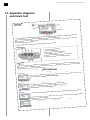
1
AUTOMATIC IMMERSED SAFETY COVER IMM'Ax Installation instructions d cove rs Slatte Please read carefully and keep for subsequent consultation Version 07/2013 an co t d dar 08 n a St 90-3 P NF m p li AE-12-010-4GB/05-2014 Installation instructions for the IMM'Ax automatic immersed safety cover - 2/36 FOREWORD This instruction manual is intended for the person who installs and commissions an ABRIBLUE safety cover. This manual must then be given to the pool owner along with the safety and user instructions so that it is available for subsequent use. The advice given in this leaflet is taken from the experience of AS POOL (ABRIBLUE): with over 55,000 automatic covers since 1995. The advice will allow the user to make the best use of this product which should give compete satisfaction to its users. Compliant with the highest requirements, our safety cover was designed to prevent children younger than 5 years old from accessing the pool when it is unrolled and locked. The floating safety cover is not a substitute for your common sense or your responsibilities. It does not replace the vigilance of a responsible adult, which remains the essential factor in the protection of young children. USEFUL ADDRESS Your retailer (stamp): 3/36 - Installation instructions for the IMM'Ax automatic immersed safety cover CONTENTS 1. Preparing the pool 1.1 1.2 1.3 Electric connections and cable passages Building work Fitting the roller 2. Delivery and reception of the roller 2.1 2.2 2.3 Placing the slats on the water Assembling the packets of slats Checking the gap Placing the stair slats Fixing the apron to the pool Fixing the anti-lifting buckles Fixing with the Coverlock system Fixing the apron to the shaft 5. Motor model with internal programmable sensors 5.1 5.2 5.3 Box with PLC (screen) Box without PLC (screen) Uncoupling 6. Motor model with external mechanical sensors 6.1 6.2 6.3 6.4 Installing the external sensor system Electric connection Testing the run stops Uncoupling 7. Accessories and options 7.1 7.2 7.3 7.4 Fitting an anti-bending console Fixture on the edges Chemical sealing with inserts Positioning the fastenings for beams 8. Test instructions in the event of a malfunction 8.1 8.2 8.3 8.4 6 6 6 6 7 Necessary tools Fitting the roller 4. Assembling the cover 4.1 4.2 4.3 4.4 4.5 4.6 4.7 4.8 4 4 5 Delivery Reception Items in the container 3. Assembling the roller 3.1 3.2 4 Checking the box Checking the power supply cable between the electric box and the roller motor Checking the key switch Direct check of the motor 7 7 12 12 12 12 13 13 14 15 17 18 18 21 23 24 24 25 27 27 28 28 28 28 29 31 31 32 32 32 9. Checks 33 10. Reception of the cover by the end user 33 11. Appendix: diagnosis assistance tool 34 Installation instructions for the IMM'Ax automatic immersed safety cover - 4/36 4 1. Preparing the pool 1.1 Electric connections and cable passages 1.1.1 Electric box power supply Fig. 1 Consult the current electric standards and in particular NF C 15-100. 0m< L <15m => 2 x 6mm2 15m< L <30m => 2 x 10mm2 3 x 2.5 mm² 30 mA 230 V 50 Hz 1.5 m 10 A 2 1.5 m 2m 2.5 m 1 2 0 3 x 1.5 mm² 5 x 1.5 mm² 0 m < D< 15 m = 2 x 6 mm2 15 m < D< 30 m = 2 x 10 mm2 Fig. 1 D - Prepare a 230 V power supply using an R2V 3G2.5 mm² (or Ro2V 3G2.5 mm²) cable for the electric box, which must be installed outside the volumes, 0 , 1 and 2 , and in a dry place (technical room). 1.1.2 Electrical protection - The power supply must be protected by a circuit breaker or a 10 A fuse holder and a 30 mA ground fault circuit breaker. 1.1.3 1.2.2 Overflow Fig. 3 - Plan to control the water level at 12 cm below the edge using a ø 50 mm overflow which is independent of the skimmers and automatic filling. Take into account that when the cover is rolled-in it will raise the water level by 10 mm. Sheaths and cable passages - Prepare a connection protected by a sheath for the 24 V DC power supply between the electric box and the box located by the roller using 2 x 6 mm² if the cable is less than 15 m and 2 x 10 mm² if the cable is between 15 m and 30 m long. - Prepare a connection protected by a sheath for the end of run stop management between the electric box and the box located close to the roller using 5 x 1.5 mm². - Prepare a connection protected by a sheath for the control between the electric box and the switch using 3 x 1.5 mm². - Separate cables carrying different voltages (24 V and 220 V) by passing them through different sheaths which are spaced in compliance with NF C 15-100. 1.2 40 cm 0cm 15 Connection box (outside volume zero and less than one metre from the pool) 50cm Fig. 2 Building work 1.2.1 Concrete belt Ø5 Fig. 2 0m m 3 - Plan a concrete belt using a 350 Kg cement per m concrete mix with a size of w 40 cm x h 50 cm x l 150 cm using at least 0.30 m3 to stabilise the fixture of the roller. Fig. 3 120mm 5/36 - Installation instructions for the IMM'Ax automatic immersed safety cover 5 mm max. 5 1.2.3 C (=F+25mm) Skimmers - When possible, plan to place the skimmers on the pool widths and not on the lengths in order to facilitate the movement of the cover. 25 mm 1.3 500 mm Fitting the roller 1.3.1 D Size of the trench Pool length in m D: Roller diameter (mm) Shaft included F: Minimum width of the technical trench 4 420 480 5 440 500 6 460 520 7 480 540 8 500 560 9 530 590 10 560 620 11 580 640 12 590 650 13 620 680 14 640 700 15 660 720 D/2 + 100 mm min. F C = Duckboard Fig. 4 Fig. 4 - Define the minimum width F of the roller trench using the following method: • Determine the inner width allowing the complete rolling of the cover using the table. Take into account the radii, circular cuts and the thickness of a masonry partition wall that is wider than the beam, which would be unusable zones for fitting the cover. 2 4 B1 B1 L • Check that: If there is a duckboard laid on the edges of the pool: F < Duckboard (in mm) - 25 mm. In the case of a duckboard covering the beam and laid on the edge: F < Duckboard - 25 mm - 100 mm. If a duckboard is not laid on the rear edge: F < Duckboard + overlap of the coping. B2 B2 A A A A 1.3.2 1 3 Squaring checks Fig. 5 - In order to correctly place your roller perpendicular to the pool lengths: measure the diagonals. Il Fig. 5 - Make a mark (1) on the pool liner at the level of the edge at the centre of the rolling trench. - Measure a precise length "A" of 1 m less than the length of the pool and make a mark (2), at the end of A on the pool liner. - On the opposite length make a mark (3) opposite mark (1). - Carry over the "A" measurement from (3) in order to place mark (4). - Measure the distance "B1" between (1) and (4) and measure the distance "B2" between (2) and (3). - If B1 and B2 are equal continue with the next step, otherwise correct the position of marks (3) and (4) and start the operation again until B1 = B2. Installation instructions for the IMM'Ax automatic immersed safety cover - 6/36 6 2. Delivery and reception of the roller 2.1 I 4.2 X 4.6 4.7 5.1 5.2 5.6 6.2 6.6 9.2 10.2 11.2 12.2 9.6 10.6 11.6 12.6 x Fig. 6 0.0.66m m 0.8mm 0.8 - Plan the presence of 2 to 6 persons, or use a handling device to handle the cover. The cover is delivered in a nonrecoverable wooden container measuring at least 40 cm more than the width of the pool. It is heavy and fragile. L 4 5 6 7 - For a 4 x 8 m pool, the container weighs 465 Kg and measures 4.6 x 0.6 x 0.8 (h). 2.2 8.2 8.6 x Delivery - For a 5 x 10 m pool, the container weighs 610 Kg and measures 5.6 x 0.6 x 0.8 (h). 7.2 7.8 Fig. 6 x 290 300 310 320 Reception - Open the container in the presence of the delivery staff and check the condition of the goods and their compliance. Keep the original packing. - If there is any damage or missing parts, write down your reserves on the transport documents (e.g.: container open on delivery). The words "subject to unpacking" alone are null and void. Send a registered letter (with acknowledgement of receipt) to the transporter within 2 days. This letter must give an exact description of the damage. Send a copy of the letter to AS POOL for information. - Store the parts in the container which should not be left in full sunlight, but should be placed in a cool place if the assembly is not carried out on the same day. - Make the inventory compared to the order. - Read the instructions completely before starting the assembly. - The installation requires 2 persons for 7 hours. 2.3 Items in the container - A slat apron - A motorised roller shaft - Two flanges to support the shaft - A 23 x 32 cm box - A slatted cover made up of a beam and duckboards (if ordered). - A partition wall (if ordered). - A fixture kit - Installation instructions x2 07:00 7/36 - Installation instructions for the IMM'Ax automatic immersed safety cover 7 3. Assembling the roller 3.1 Necessary tools Fig. 7 - Plan the equipment necessary for assembly: a perforator, a set of flat spanners, socket wrenches and hex keys, a set of screwdrivers, a mallet, pliers, a level, a glue gun, a cutter, a multimeter, a tape measure, a saw, an angle grinder and a marker. 3.2 Fitting the roller Warning: at each step check that the roller can be installed horizontally on a level and square 3.2.1 Drilling the walls Fig. 8 - Use the flanges as a template to mark the fixtures using marks 1 and 3 to place the equipment (Fig. 5). Fig. 7 Fig. 9 - Drill the wall horizontally according to the marking with 12 mm diameter holes of 70 mm depth, using a wireless drill. IMPORTANT: the notion of wireless drill is HIGHLY IMPORTANT, it means a battery operated drill (12 V). A wire powered drill is connected to the mains, i.e. to 220 V, which is highly dangerous and strictly prohibited in this situation. Fig. 8 Fig. 9 70 mm 70mmmin. mini 12mm 12 mm Installation instructions for the IMM'Ax automatic immersed safety cover - 8/36 8 3.2.2 Assembling the shaft and the flanges Fig. 10 - Assemble the motorised tube to the flange at the opposite end of the motor following these steps: • fit the stop ring to the bearing shaft which is used to stop the bearing shaft from sliding, • fit the black bearing to the bearing shaft, • place the 8 mm pin onto the shaft and slide the black bearing to hold it by covering the pin and the end of the shaft, • fix the black bearing to the bearing flange using M10 nuts. Thus the pin is trapped in the black bearing against the flange. Fig. 11 - Assemble the motorised tube with the flange on the motor side by inserting the motor end into the conical black bearing. Fig. 10 - Pin the motor end to the bearing shaft using the pin (stainless steel ring diameter 10 mm) making sure that the pin crosses the motor shaft completely. - Pass the motor cable behind the central embossing of the flange between the pin and the pool and bring it out in the upper part of the embossing. - Position the pin block. - Place the TFHC M10x60 screws. - Manually screw the plugs on these screws to slightly extend the plugs. 3.2.3 Installing the roller Fig. 12 - Slide the bearing shaft into the tube to shorten the whole. Fig. 13 - Lower the assembled roller into the pool. Fig. 11 Fig. 12 Fig. 13 9/36 - Installation instructions for the IMM'Ax automatic immersed safety cover 9 Fig. 14 - Hammer the heads of the TFHC M10x60 screws using a mallet in order to insert them into the concrete belt. - Tighten and check that the fixtures hold. Fig. 15 - Push aside the two flanges so that they touch the walls of the pool, place the blocking ring against the drive ring of the tube then securely tighten the screws on it. - Check that the shaft is horizontal and if necessary adjust using the oblong holes on the bearing of the flange on the side opposite the motor. - Check the level of the shaft at each end using a tape measure, measurement X1 should be equal to X2. 3.2.4 Place the sliders and beam boxes - Place the centre of the wall sliders using the F measurement plus 50 mm (see page 5). - Check using the beam box that the position allows the bottom of the duckboards to be level with the edge or the duckboard support and that it is correctly placed lengthwise. Fig. 14 Fig. 16 - Make the markings on the side of the pool. Fig. 17 X1 = X2 X1 - Drill the sides at the markings using a 10 mm bit for a depth of 60 mm. X2 - Place the TFHC M8x55 screws on the sliders. 0 mm Fig. 15 F +Lf 5+050m mmm 60 mm min. 60mm mini 10mm 10 mm Fig. 16 Fig. 17 Installation instructions for the IMM'Ax automatic immersed safety cover - 10/36 10 3.2.5 Install the partition wall and beam Fig. 18 - Manually screw the plugs on these screws to slightly extend the plugs. - Install the sliders and the beam boxes or only the boxes if the trench divide is in masonry. Fig. 19 - Hammer the heads of the TFHC M8x55 using a mallet in order to insert them into the concrete belt. Tighten the screws. - Adjust the height of the beam boxes depending on the height of the beam, so that the lower side of the duckboards is level with the edge and that the duckboard is supported by the side support of the beam. Fig. 20 - Assemble the side wall panels by clicking them together by placing them flat side by side and hitting them with a mallet protected by a wooden wedge from one end to the other. Fig. 18 Fig. 21 - Lower the partition wall into the pool. Fig. 19 Fig. 20 Fig. 21 11/36 - Installation instructions for the IMM'Ax automatic immersed safety cover 11 Fig. 22 - Place the beam into the boxes making sure that the end of the beam can never have less than 4 cm on each box. 40 mm min. 40mm mini 150 mm 150mmmm 40 40mm max. maxi min. mini Fig. 23 - Slide the white cylindrical cabiclips of the bungee cords into the groove in the beam. 40 mm 40mm min. mini - Thread the counterweights onto the bungee cords and spread them evenly over the width of the pool. - Check the length adjustment of the bungee cords so that the counterweights are at least 5 cm from the bottom of the pool when the cover is unrolled. 3.2.6 100maxi mm 100mm max. Fig. 22 Installing the duckboards - Carry out the electric connections, the cover assembly and the end of stop adjustments before installing the duckboards. Fig. 24 - Assemble the duckboard walkway so that each independent element weighs at least 10 Kg/part (approx . 1 m²): • Wooden duckboards are assembled side by side using the cylindrical plugs, • Aluminium duckboards are assembled by longitudinal threading and are blocked using the headless screws, • PVC duckboards are clipped together by striking the side with a mallet and a wooden wedge when they are laid side by side (from one end to the next). • When the cover is installed and the operating tests are complete, fill the connection box with sealing gel to limit the oxidation of the connections which may cause malfunctions. Fig. 23 Fig. 24 Installation instructions for the IMM'Ax automatic immersed safety cover - 12/36 12 4. Assembling the cover Special care needs to be taken when handling the slats. A shear strain on them can cause irreversible damage to the caps; this is why they must not be assembled by threading. 4.1 Placing the slats on the water Fig. 25 - Transfer the slats directly from the container to the pool water avoiding all mechanical contacts. - Prevent the slats from rubbing against the ground. Fig. 25 - Place the packets of slats directly onto the water, curved side towards the sky and the double male hook on the side opposite the roller. Place the specific groups of slats (the group fitted with straps to hook to the shaft on the roller side, the group fitted with the other anti-lifting mechanisms on the side opposite the roller, and the slats for the stairs). 4.2 Assembling the packets of slats Fig. 26 - Assemble the slats by clipping them together by inserting the double male hook into the female part of the preceding slat and then by pushing the slats up into a "V" shape towards the sky. - Make oscillating movements in order to cause click-fitting along the whole length of the slat. 4.3 Checking the gap Fig. 27 Fig. 26 - Place the cover against a length of the pool. Check that there is a gap greater than 2.5 cm between the ends of the wings and the sides of the pool (needed for operation) and less than 70 mm (otherwise the cover is no longer compliant). - Check that in the roller trench, this gap between the flanges and the ends of the wings is at least 20 mm. - 10, 15, 20, 25 and 30 mm wings are available on order. 2.5cm < x < 7cm Fig. 27 13/36 - Installation instructions for the IMM'Ax automatic immersed safety cover 13 4.4 Placing the stair slats Fig. 28 - Centre the stair cover in its housing and assemble it with the rest of the cover. To do this, make two notches in the double male hook on the first slat of the apron on either side of the stairs, in order to insert the caps of the base stair slat into the first slat of the cover. - Take care to not cut into the heart of the slat. 4.5 Fixing the apron to the pool Fig. 29 For IMM'AX, IMM'AX Solar Energy, IMM'BOX, VEESIO, NO STRESS, BANC Classic and BANC Solar Energy slatted covers, place the safety systems only on the width opposite the roller. However, for the MANU, OPEN One, OPEN Classic, OPEN Solar Energy, OPEN SURF System, BANC SURF System and DIVER slatted covers, place the safety systems on both widths of the pool (i.e. on the roller side and the side opposite the roller). x y X Y y Y x X y Y y Y x x X X y Y y x x X X Y x X y Y Fig. 28 x X y Y x < 2.5 m y < 0.6 m Fig. 29 y x X Y x X y Y Installation instructions for the IMM'Ax automatic immersed safety cover - 14/36 14 4.6 Fixing the anti-lifting buckles 4.6.1 Fig. 30 & 31 Fix the female loops on the sides 40 mm above the water line, opposite the anti-lifting mechanisms pre-installed on the slats. 4.6.2 Fig. 32 & 33 Option for fixing to the pool edge, fix the bracket support into the concrete belt, under the coping, applying the bracket against the pool side. Carry out a clipping and unclipping test on all mechanisms. Tighten the straps to press (flatten) the slats against the wall and provide good pool safety. All of the anti-lifting devices must be unlocked to handle the cover and adjust the run stops. Fig. 30 Fig. 31 Fig. 32 Fig. 33 15/36 - Installation instructions for the IMM'Ax automatic immersed safety cover 15 4.7 Fig. 34 Fixing with the Coverlock system Make sure to position the harpoons and triggers in relation to one another to obtain perfect alignment and correct operation. 4.7.1 Fig. 34 Position each front harpoon 1 on the male part of the last slat of the apron using two TFPZ 3x16 mm screws. Once all of the necessary harpoons have been installed, cut the remaining male part of the slat using a cutter and a metal saw. This will protect the liner from any damage. 1 4.7.2 Fig. 35: Fixing the triggers in the wall: Mark out the holes by placing the part 2 in the centre of the harpoon. Drill to a diameter of 6 mm and depth of 35 mm. Fix the part 2 using the TRHC M5x30 mm screws and M5 brass plugs. Make sure that this is horizontally level. Fix the face on the part 2 using the TRPZ 4x16 mm screws. 2 1 4.7.3 Fig. 36: Option for fixing the triggers on the edge: Fix the part 2 on the support 3 using the TFHC M5x16 mm screws and the M5 nuts. Then, assemble the support 3 on the edge plate 4 using the TFHC M5x16 mm screw, the whole forming an angle bracket. Centre the whole on the harpoon, then correctly flatten the support and the edge plate against the pool wall and edge. Fig. 35 Mark out the holes and a diameter of 8 mm and depth of 35 mm. drill to Finally, fix using the TFHC M6x30 mm screws and M6 brass plugs. The front face of the trigger is fixed on the part 2 using the two TRPZ 4x16 mm screws. 4 2 4.7.4 1 Fig. 37 Close the cover to connect the system. 4.7.5 Fig. 38 Secure the pool by pressing on the trigger. 3 Fig. 36 Fig. 37 Fig. 38 Installation instructions for the IMM'Ax automatic immersed safety cover - 16/36 16 4.7.6 Fig. 39 Before opening, press on the lug and pull simultaneously upwards to remove the trigger. 4.7.7 Fig. 40 Open the cover to disconnect the system. 4.7.8 Fig. 41 Install the rear harpoon by jamming it in the female part of the last slat. 4.7.9 Fig. 42 In the case of trapeze or roman stairs, a strap is provided instead of the harpoon in the sloped or rounded areas. Therefore you need to: Unclick the two slats in the place provided, make a two centimetre wide notch on the male part, pass the strap through this notch taking care to leave a washer under the slat, and clip the two slats. The strap is blocked between the slats via these two end washers. The upper washer is used for fastening in the Coverlock. Fig. 39 Fig. 40 Fig. 42 Fig. 41 17/36 - Installation instructions for the IMM'Ax automatic immersed safety cover 17 4.8 Fixing the apron to the shaft Fig. 43 - Fixing the cover to the shaft. - Place the strap fastener plates on the axis opposite the preinstalled straps on the last slat, place the loop around the strap fastener then fix it between the tube and the 30 x 80 black plate by tightening the screws. - Check that the gaps of the apron in the pool are evenly spaced on either side as soon as the rolling starts. - Correct the position of the strap fixtures if the spacing is not even. Fig. 43 - Finish the adjustment of the end of run stops once the cover's slats have been assembled. - Check the length adjustment of the bungee cords so that the counterweight does not touch the roll of slats when rolled in and does not touch the bottom of the pool when rolled out. Installation instructions for the IMM'Ax automatic immersed safety cover - 18/36 18 5. Motor model with internal programmable sensors Box with PLC (screen) 5.1.1 Electric connections Rouge/Red Rouge/Red Black/White Blanc/White Brun/Brown Bleu/Blue com. +24 V dc Ouv./Open Ferm./Close NC NO Com. Stop Stop 24Vdc 24Vdc 3 x 1.5 mm 2 2 x 1.5 mm 2 x 1.5 mm² 3 x 1.5 mm² 0V 230 AC V AC (3 x 2.5 )mm ) mm N 2 x 6 mm L Noir/Black Noir/Black Chlorinator Chlorinator 2 x 6 mm2 5.1 3 x 1.5 mm 3 x 1.5 mm² M Fig. 44 19/36 - Installation instructions for the IMM'Ax automatic immersed safety cover 19 - Have the electric connections made by a qualified technician in compliance with current standards. - Fix the transformer box in the technical room. - Install the key switch so that the cover can be controlled with a permanent view over the pool. - Place the key switch cable gland towards the bottom. - Turn the grey plate "OPEN. CLOSE." as required. - All the connections and disconnections must be made when the power is off. "BROWN" and "BLUE" taking care to respect the colours of the motor cable wires. - In the box, connect the key switch wires to terminals 4, 5 and 6 marked "COMMON", "OPEN" and "CLOSE". - Connect the treatment device to terminals 7 or 8 and 9 marked "NO", "NC" and "COMMON" if you chose to use this function. 5.1.1.2 Key switch Fig. 45 In the key switch connect: 5.1.1.1 Box Fig. 44 - In the box, connect the 230 V power cable to the domino to the left of the terminals respecting the " ", "L" and "N" symbols. - In the box, connect the motor power wires of the connecting cable to the "RED" and "BLACK" terminals taking care to respect the colours of the motor cable wires. - In the box, connect the motor sensor wires of the connecting cable to terminals 1, 2 and 3 marked "WHITE" - the wire connected to "COMMON" on the terminals marked "3" - a shunt/bridge between the two "3" terminals - the wire connected to "OPEN" on one of the terminals marked "4" - the wire connected to "CLOSE" on the other "4" terminal. 5.1.1.3 Connection box Fig. 46 - Plan M27 or M32 cable glands. - In the connection box, connect the power and sensor wires strictly respecting the colour codes "RED", "BLACK", "WHITE", "BROWN", and "BLUE" on the box card and the colours of the motor cable wires. - Use the dominoes provided for these connections. - When the cover is installed and the operating tests are complete, fill the connection box with sealing gel to limit the oxidation of the connections which may cause malfunctions. Ouv./Open Ouv./Open Com.+24 +24Vdc Com. V dc 3 4 3 4 - The connection box must be 50 cm outside of the volume 0 (see fig. 1) and accessible at any time. Ferm./CLose Ferm./Close Fig. 45 IP X6minimum minimum IP X6 Bleu Blue Bleu Blue Marron Brown Marron Brown Blanc White Blanc White Rouge Red Rouge Red M Noir Black Fig. 46 Black Noir Installation instructions for the IMM'Ax automatic immersed safety cover - 20/36 20 5.1.2 Adjusting the run stops - Switch on the box. - Press on "A" to activate the system. Fig. 47 - Initialise by pressing 3 times on "+" and then once on "OK". Fig. 48 - Indicate the motor position by placing yourself above the roller with your back to the pool: • Press once on "+" if the motor is to the right • Press once on "-" if the motor is to the left. AA BB ESC ESC -- + OK OK 3x 1x Fig. 49 - Using the key, unroll the cover and validate the position by pressing "A" once. - The PLC indicates that it has taken into account the position by displaying an "M" next to "closed pos". Fig. 47 Fig. 50 - Using the key, roll in the cover and validate the position by pressing B once when rolling in is complete. - The PLC indicates it has taken into account the position by displaying "stop". - Restart the initialisation step: Press 3 times on the + key, then on "OK" if you wish to reprogramme. M - Invert the wires connected in the box on "OPEN" and "CLOSE" if the cover movement does not correspond to the "OPEN CLOSE" indications on the grey plate of the key switch. A B ESC - + OK 1x A B ESC - + OK + OK M 1x Fig. 48 OUV. FERM. 0 0UV. FERM. 0 A A B ESC - + OK 1x Fig. 50 1x Fig. 49 B ESC - 21/36 - Installation instructions for the IMM'Ax automatic immersed safety cover Box without PLC (screen) Electric connections 30V 230 VAC AC (3 x 2.5 mm 2.5mm ) ) 2 NO NO NC NC Com.. Com Black/White Blanc/White Brun/Brown Brun/Brown Bleu/Blue Bleu/Blue Com. +24Vdc com. +24 V dc Ouv./Open Ouv./Open Ferm./Close Ferm./CLose NN 1.5 mm mm² 3 3xx1.5 LL Noir/Black Noir/Black Rouge/Red Rouge/Red Chlorinator Chlorinator 2 5.2.1 mm 2 2x x66mm 5.2 21 1.5 mm² 22xx 1.5 mm x 1.5 mm² 3 x31.5 mm M Installation instructions for the IMM'Ax automatic immersed safety cover - 22/36 22 - Have the electric connections made by a qualified technician in compliance with current standards. 5.2.1.3 Connection box - Fix the transformer box in the technical room. - Plan M27 or M32 cable glands if you use the 2 x 10 mm² cable. Fig. 53 - Install the key switch so that the cover can be controlled with a permanent view over the pool. - In the connection box, connect the power and sensor wires strictly respecting the colour codes "RED", "BLACK", "WHITE", "BROWN", and "BLUE" on the box card and the colours of the motor cable wires. - Place the key switch cable gland towards the bottom. - Turn the grey plate "OPEN. CLOSE." as required. - All the connections and disconnections must be made when the power is off. - Use the dominoes provided for these connections. - When the cover is installed and the operating tests are complete, fill the connection box with sealing gel to limit the oxidation of the connections which may cause malfunctions. 5.2.1.1 Box Fig. 51 - In the box, connect the 230 V power cable to the domino to the left of the terminals respecting the " ", "L" and "N" symbols. - The connection box must be 50 cm outside of the volume 0 (see fig. 1) and accessible at any time. - In the box, connect the motor power wires of the connecting cable to the "RED" and "BLACK" terminals taking care to respect the colours of the motor cable wires. - In the box, connect the motor sensor wires of the connecting cable to the terminals marked "WHITE" "BROWN" and "BLUE" taking care to respect the colours of the motor cable wires. - In the box, connect the key switch wires to the "Key" terminals marked "COMMON", "OPEN" and "CLOSE". - Connect the treatment device to the "Chlorinator" terminals marked "NO", "NC" and "COMMON" if you chose to use this function. 5.2.1.2 Key switch Ouv./Open Ouv./Open Fig. 52 Com.+24 +24Vdc Com. V dc In the key switch connect: - the wire connected to "COMMON" on the terminals marked "3" - a shunt/bridge between the two "3" terminals - the wire connected to "OPEN" on one of the terminals marked "4" 3 4 3 4 Ferm./CLose Ferm./Close - the wire connected to "CLOSE" on the other "4" terminal. Fig. 52 IP X6minimum minimum IP X6 Bleu Blue Bleu Blue Marron Brown Marron Brown Blanc White Blanc White Rouge Red Rouge Red Noir Black Black Noir M Fig. 53 23/36 - Installation instructions for the IMM'Ax automatic immersed safety cover 23 5.2.2 Adjusting the run stops Fig. 54 - 55 - 56 - Switch on the box. - Switch the box's switch to "Manual". Auto Auto - Using the control key, activate the cover and check that the direction of rotation of the shaft corresponds to the request. (The slats must always pass over the shaft). 5s 5s - In the box, invert the motor power wires, connected on the "red" and "black" terminals, if this is not the case. Led LED - Switch the box's switch to "Auto". - Initialise the programming by pressing the yellow push button (approx. 5 seconds), and releasing when the LED flashes. Fig. 54 - Using the control key, completely roll-in the cover. - The key can be turned several times during opening to adjust the cover to the optimum position. (the key can be released then turned again during opening). - The position of the Opening run stop is stored in memory while turning the key during Closing. 0UV. FERM. - Validate this position by closing the pool using the control key. 0 - Unroll the cover. - The key can be turned several times during closing to adjust the cover to the optimum position. (the key can be released then turned again during closing). - The position of the Closing run stop is stored in memory while turning the key during Opening. Fig. 55 - Validate this position by opening the cover using the key. - Once the pool is open, close it again. - The end of run stop adjustment is complete. 5.3 0UV. FERM. 0 Uncoupling - Switch off the box. - Block the rotation of the shaft while keeping the slats rolled around. - In the motor connection box located close to the pool, disconnect the sensor wires and the power from the motor cable in order to slide it completely towards the shaft. The cable must be completely free from any constraints. Fig. 56 - Remove the pin blocker to access. Turn the stainless steel pin a quarter turn so that it is perpendicular to the wall, and pull. The cover axis now rotates freely. - Manually accompany the unrolling of the cover, making sure that the motor cable does not get entangled. - Lock the safety mechanisms. When commissioning the roller, a new adjustment of the motor end of run stops will be needed. Installation instructions for the IMM'Ax automatic immersed safety cover - 24/36 24 6. Motor model with external mechanical sensors 6.1 Fig. 57 Installing the external sensor system Fig. 57 Before placing the duckboards, install the sensor by sliding the support ring in the beam groove and position the counterweight behind the roller. Fig. 58 Place the sensor on the part of the apron that will roll up last (e.g. if you have roman stairs, place it in the middle). Fig. 59 Installation to be carried out. Adjust the 2 support plates to reduce or extend the length as required and place the external sensor in the following position. Warning, the metal strip of the sensor (bottom) must never be in contact with the shaft. This may cause the strip to pass in front of its detector and cause an unjustified run stop. Fig. 60 Fix the sheath attachment clips on the beam by pre-drilling Ø 3.5 mm holes at equal distance. Fig. 58 Screw the clips directly using the screws provided. Place the 2 cables of the detectors in the sheath and insert it into the clips. The sensor cables must reach the connection box. Fig. 59 Fig. 60 25/36 - Installation instructions for the IMM'Ax automatic immersed safety cover Electric connection 6.2.1 Box Fig. 61 2A 2A 2A 2A + 1 2 3 4 5 6 7 C O F N P T KM1 KM2 + 1 2 3 4 M 22xx 66 mm mm 2 Com. Com. NO NO NC NC Com. +24Vdc Com.+24Vdc Ouv./Open Ouv./Open Ferm./CLose Ferm./Close 6.2 25 N N P 230V 230 V AC AC 2.5 mm ) ) (3 x(3 x2.5mm 2 Chlorinator Chlorinator 1.5 mm² 44xx 1.5 mm 1.5 mm² 33xx 1.5 mm 1.5 mm mm² 2 2x x1.5 Fig. 61 Installation instructions for the IMM'Ax automatic immersed safety cover - 26/36 26 - Connect the 230 V power cable to the terminal respecting the "earth", "N" and "P" symbols. - Connect the motor power wires of the connecting cable to the "+" and "-" terminals. - Connect the 4 connecting wires for the external sensor to terminals 1, 2, 3 and 4. - Connect the treatment device to terminals 5 for the common, 6 NO or 7 NC if you chose to use this function. - Connect the key switch wires to the "C" common, "O" open and "F" close terminals. 6.2.2 Key switch Fig. 62 - the wire connected to "COMMON" on the terminals marked "3" - a shunt/bridge between the two "3" terminals - the wire connected to "OPEN" on one of the terminals marked "4" - the wire connected to "CLOSE" on the other "4" terminal. 6.2.3 Connection box Fig. 63 - Connect the external sensor by connecting the two brown wires together in the domino corresponding to wire 1, the two blue wires in the domino corresponding to wire 2, one of the black wires in the domino corresponding to wire 3 and the other with domino 4. - -Connect the motor power wires strictly respecting the colour codes "Red" and Black". Ouv./Open Ouv./Open - The connection box must be 50 cm outside of the volume 0 (see fig. 1) and accessible at any time. Com. V dc Com. +24 +24Vdc 33 44 33 44 Ferm./CLose Ferm./Close Fig. 62 4 Noir Black 2 Bleu Blue Bleu Blue Marron Brown Marron Brown 1 Noir Black 3 + Rouge Red Noir Black Fig. 63 M 27/36 - Installation instructions for the IMM'Ax automatic immersed safety cover 27 Fig. 64 6.3 Testing the run stops Operation: Fig. 64 Cover in open run stop position. The first slat of the apron has passed the top sensor strip, it falls and is therefore not in front of its detector. Opening of the system stops. Fig. 65 The cover starts operating again during closing. The apron unrolls on the pool. Fig. 66 Cover in closed run stop position. The last slat of the apron has passed the bottom sensor strip, it falls and is therefore not in front of its detector. Closing of the system stops. Warning, if closing is incorrectly stopped: Fig. 65 - cover stopped too soon, there is a space over the pool. - cover stopped too late, the slats are compacted and lift up from the surface of the water. Adjust the number of slats on the pool or remove slats). 6.4 Fig. 66 Uncoupling 6.4.1 Switch off the box. 6.4.2 Block the rotation of the shaft while keeping the slats rolled around. 6.4.3 In the connection box located close to the pool, disconnect the power wires (+ and -) from the motor cable in order to slide it completely towards the shaft. The cable must be completely free from any constraints. 6.4.4 Remove the pin block to access. Turn the stainless steel pin a quarter turn so that it is perpendicular to the wall, and pull. The cover axis now rotates freely. 6.4.5 Manually accompany the unrolling of the cover, making sure that the motor cable does not get entangled. 6.4.6 Lock the safety mechanisms. 6.4.7 When commissioning the roller, a new adjustment of the motor end of run stops will be needed. Installation instructions for the IMM'Ax automatic immersed safety cover - 28/36 28 7. Accessories and options 7.1 7.2.3 - Make sure that the height adjustment of the bottom of the duckboard corresponds to your needs. Fitting an anti-bending console - The fixture to the edge of the 120 mm beam makes it possible to place this face 11 mm above the edge and up to - 8 mm. Fig. 67 - Plan a concrete belt using a 350 Kg cement per m3 concrete mix with a size of w 25 cm x h 40 cm x l 100 cm using at least 0.10 m3 to stabilise the fixture of the anti-bending console. - The fixture to the edge of the 80 mm beam makes it possible to place this face 5 mm above the edge and up to - 13 mm. - Place the anti-bending console on the edge and against the rear wall of the pool. - Assemble the stainless steel fixing plate to the vertical beam box support using the stainless steel studs in the upper part of the vertical support. - Mark the edges. - Install the arm (1) horizontally by correctly placing the vertical part of the bracket (2) against the pool wall (3). - Install the wedges under the horizontal plate if there is a liner attachment rail for example, or behind the vertical support to deliberately give an angle to the console in order to obtain a horizontal beam once the duckboard walkway is in place. - A more accurate adjustment of the beam height is carried out using the bracket's oblong holes (4) and must maintain the bottom of the supporting brackets 4 cm above the water line. 7.2 Fixture on the edges 7.2.1 Fixing the flanges to the edge. Fixing the beam boxes to the edges - Use the stainless steel supports as a template for step 3.2.5 of the assembly and marking. - Make two fixtures on each side. 7.3 Chemical sealing with inserts - For M8 screws, drill to a diameter of 14 mm and depth of 65 mm, - For M10 screws, drill to a diameter of 20 mm and depth of 70 mm, - Clean the holes by blowing. - Inject a dose of chemical sealer and place the insert, - Respect the drying time indicated on the cartridge. Fig. 68 - Assemble the stainless steel fixing plate with the cover using the M10 nuts and washers. - Use the stainless steel supports as a template to mark the position of the 4 fixing holes on each side of the pool (they must be carried out as close as possible to the pool depending on the structure's reinforcement elements) 1 2 - Drill 12 mm diameter holes at a depth of 70 mm. - Manually screw the brass plugs to the TFHC M10x60 screws through the stainless steel plate. 3 Fig. 67 - Hammer the heads of the TFHC M10x60 screws using a mallet in order to insert them into the concrete belt. - Tighten and check that the fixtures hold. - If necessary used the supplied wedges to ensure that the edge plates are horizontal. 7.2.2 Fixing the sliders to the edge Fig. 69 - Assemble the stainless steel fixing plate to the slider using the stainless steel studs on the top part of the slider. Fig. 68 - Use the stainless steel supports as a template to mark the position of the 2 fixing holes on each side of the pool. - Drill 10 mm diameter holes at a minimum depth of 60 mm. - Manually screw the brass plugs to the TFHC M8x55 screws through the stainless steel plate. - Strike the heads of the TFHC M8x55 screws using a mallet in order to insert them into the concrete belt. - Tighten and check that the fixtures hold. - The beam box is fitted to the slider using M8 nuts. Fig. 69 4 29/36 - Installation instructions for the IMM'Ax automatic immersed safety cover Positioning the fastenings for beams fastening level with the coating Position 1 Liner fastening level with the coating beam support neoprene seal 80 mm beam 120 mm beam WŽƐŝƚŝŽŶŚĂƵƚĞ͗ WŽƐŝƚŝŽŶŚĂƵƚĞ͗ Top position 35 mm 75 mm Top position 50 mm edge 50 mm edge 15 mm WŽƐŝƚŝŽŶďĂƐƐĞ͗ Bott om Bott ompositi position on 55 mm Bottom position WŽƐŝƚŝŽŶďĂƐƐĞ͗ edge 70 mm edge 70 mm 7.4 29 Installation instructions for the IMM'Ax automatic immersed safety cover - 30/36 30 Position 2 edge 30 mm Liner fastening level with the coating beam support neoprene seal 120 mm beam Top positi on WŽƐŝƚŝŽŶŚĂƵƚĞ͗ 45 mm 80 mm beam Top positi on WŽƐŝƚŝŽŶŚĂƵƚĞ͗ edge 80 mm 5 mm 80 mm edge Bott om position WŽƐŝƚŝŽŶďĂƐƐĞ͗ edge 25 mm edge 100 mm WŽƐŝƚŝŽŶďĂƐƐĞ͗ 100 mm Bottom position 15 mm 31/36 - Installation instructions for the IMM'Ax automatic immersed safety cover 8. Test instructions in the event of a malfunction The following list has been drawn up in order to help diagnose and correct malfunctions that may occur during installation. This guide is exclusively for the professional authorised to install the cover in order to maintain the validity of the guarantee. If, after having followed these instructions, the cause of the malfunction has not been found, the professional must contact the cover retailer or manufacturer. Read completely before carrying out the operations. Refer to figures 25 and 27. Turn the switch on the box to Off or "0" before each connection, disconnection operation. Check the condition and the correct tightening of the electric connections. 8.1 Checking the box 8.1.1 Check that the fuse and the thermal circuit breaker are in good condition. 8.1.2 Check the power relay operation. 8.1.3 Disconnect the 2 wires connecting the box to the roller motor from the "+" and "-" terminals. 8.1.4 Turn the switch on the box to On or "1" 8.1.5 Check that the command and power diodes are on when the box is powered on. 8.1.6 Step by step, measure the presence of the indicated voltage on the following terminals: 8.1.7 Electric box power supply test: 230 V AC (Alternating) on the "L" and "N" terminals of the electric box to which the 230 V is connected. 8.1.8 Transformer test: 20-24 V AC between the red and blue jacks, and 10-12 V AC between the White and Blue jacks exiting the transformer. 8.1.9 Motor terminal tests: 24 V DC between the "+" and "-" terminals of the motor when activating an open or a close. 8.1.10 Terminal tests: If there is a malfunction check that the cable terminals are correctly connected to the card. 8.1.11 If a voltage is not present or a value is different, check again making sure that the multimeter tips are in contact with the terminals and that your multimeter is calibrated and on the correct measurement position. A voltage that is absent or different from the indicated voltage indicates that the tested component is defective. Replace it or request its return to AS POOL for analysis. 8.1.12 If the box is correctly supplied, the fuses in good condition, and if the cover does not move, the box is no longer operational (this can be due to a power surge from an incorrect connection, a thunder storm or a defective component. The box must be returned to AS POOL for analysis). If the cover moves more than 1 metre: the box is working correctly. 31 Installation instructions for the IMM'Ax automatic immersed safety cover - 32/36 32 8.2 Checking the power supply cable between the electric box and the roller motor 8.2.1 Reconnect the roller power cable to the box and disconnect it from the junction box. 8.2.2 Step by step, measure the presence of the indicated voltage on the following terminals: 8.2.3 Connecting cable test: 24 V DC on the electric box terminals marked "+" and "-" at the connecting cable connections. Then 24 V DC on the terminals for the 2 wires arriving at the junction box. If the voltage is below 22V, this voltage will not be sufficient for the correct operation of the motor. 8.2.4 Check that the cable sections correspond to what is indicated on fig. 1, the quality of the connections (make sure of the continuity of the connections in the junction box and the box), the absence of humidity or even water in the connection box (Reminder: the connection box must always be filled with gel). 8.2.5 If the voltage is not present or the value is different, this means that your cable is defective, cut, damaged or has the wrong resistance, or is located too near to a cable with a different voltage that disrupts its operation. Replace the cable. Make a temporary connection using another cable directly between the electric box and the motor to carry out new tests. 8.3 Checking the key switch 8.3.1 Use the continuity measurement of your multimeter to check that the contacts (NO) located behind the switch close one after the other when the key is turned first in one direction and then in the other. 8.3.2 In the box Measure 24 V DC between the "com" and the "open" when the key is on "open". Measure 24 V DC between the "com" and the "close" when the key is in the "close" position. 8.4 Direct check of the motor 8.4.1 If the cover does not move, check the motor sensor operation (return data) by checking: • the good condition of the motor cable • the correct placement of the stainless steel blocking ring against the roller tube so that the flanges are correctly flattened against the pool walls. 8.4.2 If these elements are correct, the motor sensor is out of order (this can be due to a power surge related to a faulty connection, a storm or a defective component. The motor must be returned to AS POOL for analysis). 33/36 - Installation instructions for the IMM'Ax automatic immersed safety cover 9. Checks Check the following points relating to standard NF P 90-308 and check that the cover operates correctly: • When turning the key switch for the cover, the entire pool is visible and check that there are no bathers in the pool when closing the cover. The unrolling operation stops when the key is released. The key can be removed from the control box. • The cover rolls and unrolls correctly. • The safety mechanisms are easily handled for the recommended water levels and are sufficient (number and position). Check that they are locked on completion of the installation. • The gaps along the length between the slats of the apron and the pool wall are less than 7 cm and the apron does not rub "abnormally" against the wall. • The slatted cover (duckboards) is stable and resists intrusion and lifting by a force of less than 50 N. • The space between the bottom of the beam supporting the duckboards of an immersed cover and the partition wall is 150 mm maximum. • The gap at the bottom of the partition wall and the bottom of the pool is less than 100 mm. • The voltage powering the cover is less than 30 V DC. • The end of runs stops (if they exist) operate. • The site is cleaned after installation of the cover and the packaging and waste is removed. • The user manual has been given to the end user. • The cover's guarantee form is filled in and signed. 10. Reception of the cover by the end user • The installer explains the operation of the ABRIBLUE cover to the end user and informs him/her of the safety, usage, upkeep and winterisation advice. • He gives him/her the cover's instructions. • He demonstrates the use of the cover and shows the functional limits of the cover. The installer and end user fill in and sign the guarantee form attesting to the compliance of the installation, the reception of the documents for the cover and the information given to the end user. 33 Installation instructions for the IMM'Ax automatic immersed safety cover - 34/36 34 11. Appendix: diagnosis assistance tool /ŶĨŽƌŵĂƟŽŶ WŽƐŝƟŽŶ͗ ůŽƐĞĚ͗ KƉĞŶ͗ Intensity ^ƚĂƚƵƐ͗ŽƉĞŶŽƌ closed ZŽƚĂƟŽŶĂůƐƉĞĞĚ tĂƌŶŝŶŐŵĞƐƐĂŐĞ ŽǁŶƌŽƚĂƟŽŶƐ ƉĞŶŝŶŐͿŽƌĐŽƵŶƚĞĚĚ ŶŽ ŚĞ ;ǁ ŶƐ ƟŽ ƚĂ ƌŽ ŶƵŵďĞƌŽĨĐŽƵŶƚĞĚ ŚĞƌŽƚĂƟŽŶĂůƐƉĞĞĚ͘ Ěƚ ĂŶĞŶƚůLJĚŝƐƉůĂLJƐƚŚĞ ƚĞƌ ŝŶ ƚŚĞ ŽƉĞŶ ϭ͘dŚĞƐĐƌĞĞŶƉĞƌŵ ŝŶĚŝĐĂƚĞƐƚŚĞĐŽŶƐƵŵĞĚŝŶƚĞŶƐŝƚLJĂŶ ŝƐ ůĞƐƐ ƚŚĂŶ ƚŚĞ ǀĂůƵĞ ŽĨ ƚŚĞ ĐŽƵŶ ϬͿ ůƐŽ ŶĚ ;ǁŚĞŶĐůŽƐŝŶŐͿ͘/ƚĂ ƐĞĚ ƉŽƐŝƟŽŶ ;ĂƌŽƵ ĐŽƵŶƚĞƌ ŝŶ ƚŚĞ ĐůŽ dŚĞ ǀĂůƵĞ ŽĨ ƚŚĞ ͘ ϳϬϬϬĂŶĚϴϬϬϬͿ ƉŽƐŝƟŽŶ;ďĞƚǁĞĞŶ ŬĞLJŝƐƚƵƌŶĞĚ͘ ƐĞĐŽŶĚǁŚĞŶƚŚĞ ůĨĂ ŚĂ Žƌ ƉĨ ƚͲƵ Ăƌ Ɛƚ ŽƚŽƌ Ϯ͘ƟŵĞƌĚĞůĂLJƐŵ dƌŽƵďůĞƐŚŽŽƟŶŐ͗ ĞƉƌĞƐĞŶƚ ϭ͘ŽŵŵĂŶĚǀŽůƚĂŐ ƐĞŶƚ ƌĞ ĞƉ ĂŐ Žůƚ ƌǀ Ϯ͘WŽǁĞ ͲĐůŽĐŬǁŝƐĞƌŽƚĂƟŽŶ ϯ͘DŽƚŽƌůŝŐŚƚ͗ĂŶƟ ŝƐĞƌŽƚĂƟŽŶ Ŭǁ ϰ͘DŽƚŽƌůŝŐŚƚ͗ĐůŽĐ ŶŝŶĂŶƟͲĐůŽĐŬǁŝƐĞĚŝƌĞĐƟŽŶ ƩŽ ϱ͘DŽƚŽƌĨŽƌĐŝŶŐďƵ ŶŝŶĐůŽĐŬǁŝƐĞĚŝƌĞĐƟŽŶ ƩŽ ďƵ ŶŐ ƌĐŝ ĨŽ Žƌ Žƚ ϲ͘D e ese contacts are fre contact is open. Th ͗Ϭ͘Ϯ ĂƚϭϮϱsĂĐ͕ NC e th d, se clo is t ͕ŝŶĚƵĐƟǀĞůŽĂĚ on, the NO contac ϭϮϱǀ͕ϭĂƚϯϬs sed the info LED is When the pool is clo ƵƚͲŽī ƉŽǁĞƌ͗ ƌĞƐŝƐƟǀĞůŽĂĚ͗Ϭ͘ϯĂƚ ů͘ ͕ϮϮϬs͘ ŽĨĞůĞĐƚƌŝĐƉŽƚĞŶƟĂ Ădž͘ǀŽůƚĂŐĞ͗ϮϱϬsĂĐ ͕ŵ s Ϭ͘Ϭ͘ϱĂƚϯϬ ^'^ ŽŶƚĂĐƚŝŶĨŽ͗ ZZKZD^ Sensor error Cycle error Overload Ğ ƐƚĂƚƵƐ͘ dŚĞ ƌĞŵĂŝŶƐŝŶ ƚŚĞ ƐĂŵ ƟŽŶ͘ Ăů ŐŶ Ɛŝ Ğƌ Ŷƚ ŽƵ ǀĐ dŚĞ ƌĞ ŽƌĐŽŶŶĞĐ m. ŚĞĐŬƚŚĞƐĞŶƐ relaunch the syste ĂŶĞǁƌĞƐĞƚĐĂŶ ƐLJƐƚĞŵũĂŵƐ͘ KŶůLJ Ɛ͘ ƵƉƉůLJĨŽƌϱŵŝŶƵƚĞ ƚĞƌƌƵƉƚĞĚƉŽǁĞƌƐ ŽƉƉĞĚĨŽƌϮϬƐĞĐŽŶĚƐ͘ ŶŝŶ ŶƵ ƐĂ ŚĂ Žƌ Žƚ ŝƐƐƚ dŚĞŵ ĚĞĚĂŶĚƚŚĞŵŽƚŽƌ dŚĞĂĐƟŽŶŝƐƐƵƐƉĞŶ ƌŝĞĚŽƵƚĚƵƌŝŶŐƚŚŝƐƟŵĞ͘ Ăƌ EŽĂĐƟŽŶƐĐĂŶďĞĐ ϭϬ͘ ĞŶƐŝƚLJŐƌĞĂƚĞƌƚŚĂŶ ŽƚŽƌ͖ŽƉĞƌĂƟŶŐŝŶƚ ŵ ŚĞ Ěƚ ƉĞ ŽƉ Ɛƚ ĂƐ ďƌĞĂŬĞƌŚ dŚĞĞůĞĐƚƌŝĐĂůĐŝƌĐƵŝƚ ŇĂƐŚ ͕ ƚŚŝƐ ĚŝƐƉůĂLJ ǁŝůů ŽĐĐƵƌƐ ƚŚƌĞĞ ƟŵĞƐ ƌ ƌŽ Ğƌ ŝƐ ƚŚ ŝĨ ͕ ĐůĞ Žƌ ĐůŽƐƵƌĞ ĐLJ KŶ ƚŚĞ ƐĂŵĞ ŽƉĞŶ ƉŽƐŝƚĞ͘ ŽƉ ĞŶ ĐƌĞ ĞƐ ƚŚ ŽdžKŶͬKīƐǁŝƚĐŚ͘ ƐŚŽǁŝŶŐ ͕ƉƌĞƐƐƚŚĞĐŽŶƚƌŽůď ŵ ƐƚĞ ƐLJ ŚĞ ƚƚ ƐĞ ƌĞ dŽ 35/36 - Installation instructions for the IMM'Ax automatic immersed safety cover 35 36 Installation instructions for the IMM'Ax automatic immersed safety cover - 36/36 Product: IMM'Ax Company: AS POOL Address: ZAC de la Rouvelière F-72700 F 72700 SPAYSPAY LE MANS Tel.: +33 (0)811 901 331 Fax: +33 (0)243 479 850 [email protected] www.abriblue.com ABRIBLUE LINE Slatted covers Safety instructions and user guide for automatic pool covers Please read carefully and keep available for later use Version 02/2013 AE-012-138-3GB/05-2014 Safety instructions and user guide for automatic pool covers - 2/8 2 CONTENTS 1. Safety Advice 2. Advice for use 3. Upkeep advice 4. Maintenance advice 5. Winterisation advice 6. Guarantee 2 3 4 5 6 6 Compliance certificates 1. Safety Advice WARNING: The pool can constitute a serious danger to your children. Drowning happens very quickly. Children close to a pool require constant monitoring and active supervision even if they can swim. The physical presence of a responsible adult is indispensable when the pool is open. Learn the actions that save lives. Memorise the emergency service phone numbers and display them near the pool: Fire Brigade: 112 Emergency Services: 15 Poison Centre: Write down the No.: .......... • This cover is not a substitute for common sense or personal liability. Its aim is not to be a substitute for the vigilance of parents and/or responsible adults, which remains the essential factor in the protection of young children. • Be aware that safety is only assured with a closed, locked cover which is correctly installed in compliance with the manufacturer's instructions. • The cover must be systematically unrolled and locked during absences, however short, from the home. • Check that there are no bathers or foreign bodies in the pool before activating the cover. • Keep the tools needed to activate the covers out of the reach of children. • Only a responsible adult should undertake to manoeuvre the cover. • It is prohibited to climb onto, walk on or jump on a safety cover. • Take all necessary measures to prevent access to the pool by young children, until the cover is repaired, or when a malfunction prevents the closure of the cover to secure the pool, or if the pool equipment is temporarily unavailable. • Comply with the water levels defined by the manufacturer. This document is the property of AS POOL - of the NextPool group and cannot be reproduced or communicated without our authorisation. 3/8 - Safety instructions and user guide for automatic pool covers 2. Advice for use 3 • Do not operate the cover more than 15 consecutive minutes. • Always check that the pool water level remains constant and in compliance with the manufacturer's recommendations (-12 cm as a standard) before using the cover in order to avoid jamming the slats in the trench (against the beam or the partition wall), or to prevent them from rubbing against the pool copings, or to avoid the slats being warped by excess or insufficient water levels. Make sure that the overflow and the water level regulator are operational so that the skimmers do not suck in air if the water level is too low. • It is prohibited to manoeuvre the cover if there is a load on the duckboard walkway of an immersed cover, this might cause the cover to scrape the beam. • Remove all floating objects that could hinder the correct operation of the ABRIBLUE cover during its closure, and lock the access to the pool using the blocking straps. • Do not walk or jump on the covering of the BANC roller in order to avoid deforming it. • Do not forget to unlock the safety mechanisms before opening the pool cover as failure to do so may damage the pool cover. • Always keep the pool in full view during the opening and closing operations. It may be necessary to accompany the cover manually during rolling or unrolling operations in order to position it correctly if there is a strong side wind, a free form pool, or a pool with a specific configuration. • It is imperative not to halt the cover in an intermediate position, this can cause the risk of jamming a bather's body at the level of the cover casing, if a bather uses the pool. The person carrying out the action must make sure there are no bathers in the pool before starting. • Check that the hose or power supply cable of the pool cleaner does not get tangled in the cover; this could jam the operation of the roller and damage the PVC slats. • Check that unrolling and rolling runs correctly over the first few metres (the slats roll effortlessly, there is no jamming on the shaft with the top "bulging" towards the outside of the roll), and if necessary, stop the action immediately in order to intervene on the cause of the malfunction. • The rotational speed of the shaft is not constant due to the rolling/unrolling of each new layer of slats which unbalances the roller. Adapt the wheel's rotational speed on the manual model in order to avoid the harder spots by handling the wheel with both hands. • Prohibit an overload on the duckboard walkway for an immersed cover due to the physical limits of the beam and the fixtures. The duckboard walkway is supported by the pool edge and the beam, and is designed to support a maximum load of 400 kg over its complete length (duckboard included) and 150 kg per linear metre. • It is essential, for safety reasons, to remove the key from the control box or the manual wheel once the opening or closure actions are complete. • Programme the filtering system to start as soon as the "solar" slats are in sunlight. During very sunny periods with the cover closed, the water temperature can reach 30° or more and can damage the slats. • It is strongly recommended not to empty the pool without the authorisation of your installer. • If the cover is fitted with a WING System®, take care not to operate the cover without having folded the WING System® onto the cover. Operating the cover with the WING System® deployed can cause major damage to the cover and the pool. • If the cover is fitted with a SURF System (mobile roller), make sure the roller is correctly positioned on the pool before any automatic action of the slats. • In the case of an emergency operation, a person walking on the cover will have his/her feet under the water. • Limit operating the cover when the temperature is below 5 °C and do not handle the cover below 0°C when it is locked in ice. Avoid all shocks and mechanical contacts on the slats when the temperature is below 0°C. • When the cover is installed on a sheltered pool, make sure that the air temperature is no higher than 40 °C. Make sure that the surrounding air is ventilated in order to avoid all distortions and deteriorations of the parts (PVC slats, bench panels, duckboards, etc.). • It is imperative during rolling or unrolling operations, not to release the key until the end of run stops have been reached (especially on the BANCS) in order to correctly position the slats on the shaft when rolling in is complete, or on the water when unrolling is complete. • On the model without run stops, make sure not to rollin the slats too much in order to prevent them from falling to the rear and breaking. This document is the property of AS POOL - of the NextPool group and cannot be reproduced or communicated without our authorisation. Safety instructions and user guide for automatic pool covers - 4/8 4 3. Upkeep advice The maintenance of the ABRIBLUE automatic cover is at the expense and under the responsibility of the user. • Check that the slats are not subjected to temperature differences greater than 15° between the outside air and the water in order to prevent them from warping (case of a highly heated pool in a cold environment: mountain for example). • The use of an automatic cover maintains the quality of the water and reduces the amounts of treatment products needed. • When using a cover installation under a shelter, make sure the shelter is aired and limit its temperature to 40 °C maximum and prevent the slats and bench panels from overheating. • Maintain a good water balance in order to avoid damaging your automatic cover. Water characteristics Minimum recommended value Maximum recommended value pH 7.2 7.6 Chlorine 0.7 ppm 1.2 ppm Bromine 1.5 ppm 2.5 ppm TA 80 ppm 120 ppm TH 100 ppm 300 ppm Stabiliser 10 ppm 40 ppm Temperature 1°C 30°C • Prolonged or repeated overdoses of products are damaging to the PVC slats. An acid pH below 7 can corrode metal parts. A lack of treatment causes the proliferation of algae and favours the putrefaction process which can cause the irreparable appearance of brown stains on the PVC slats. • Check the operation of the electrolyser when the pool is closed for long periods. This type of device cannot be fitted with a stop in production and can cause irremediable damage to submerged mechanisms (corrosion) in the event of a high concentration of stagnant chlorinated products in contact with the PVC slats. To correct this situation, occasionally air the pool water by opening the cover taking care to guard the access to the pool while it is open. • During a super-chlorination operation, roll up the cover, start the filtering system and guard the access to the pool from children under 5 years old. • Clean your cover at least twice a year using a high pressure cleaner or a sponge using a descaling product and/or a degreasing product (water line gel type). Do not use a solvent or abrasive product as these may damage the PVC slats. Do not spray water onto the shaft as this might damage the motor. • Protect wood elements such as duckboards and bench panels. Wood, whatever its origins, is subjected to the aggression of the environment on a daily basis: walking, bad weather, dampness or dry weather. It therefore needs a minimum of maintenance. Prefer a wood saturator. For it to be efficient we recommend that you apply it using a brush until saturation in order to stabilise it and avoid tannins from being rejected. The coats must be applied when the previous coat is still damp, without any drying time between them (2 or 3 coats according to the porosity). Avoid wax or silicone based products, they are very quickly decomposed by UVs and washed away in bad weather. Depending on climatic conditions, exotic woods become silvery grey over time. Avoid varnishes and surface coatings, they form unstable films which are subject to flaking. We recommend the products Durieu DESKS OLJE D1 (mentioned in the "Techniques PISCINES" review) for the maintenance of exotic woods. If you have tannin stains on your pool copings or protective cover, we recommend the application of concentrated bleach using a brush followed by copious rinsing. • Do not cover the opaque slats with a hermetic tarpaulin, this would risk creating a major heating effect (greenhouse effect) which could cause the slats to warp permanently. • Check the good condition, tightness and correct fixture of the safety loops. • Check that the straps linking the slats to the shaft are always tightly in place and evenly distributed. • Check the ends of the slats, check that they are aligned and that the caps and wings are not broken. A slat not aligned with the rest of the cover could jam when the cover is moving and cause major damage. • During the summer period, clean the slat storage trench once a month using a manual vacuum brush. Regularly remove any debris lying on the cover. • Check the correct operation of the water level regulation (overflow not clogged, automatic filling correctly set) • Make sure that the area where the cover motor is located is fitted with a drain preventing the motor from being immersed at all times (in case of flooding). This document is the property of AS POOL - of the NextPool group and cannot be reproduced or communicated without our authorisation. 5/8 - Safety instructions and user guide for automatic pool covers 4. Maintenance advice In the event of a malfunction or a repair preventing the closure and the securing of the pool, take all necessary measures to prevent the access to the pool of children under 5 years old. • AS POOL (ABRIBLUE) only distributes its technical products via a network of pool professionals which carries out the installation and follow-up depending on the specificities of the pool. AS POOL (ABRIBLUE) does not communicate directly with the pool owners. Have the automatic cover serviced by a swimming pool professional (we recommend your swimming pool installer whose details are on the cover of this manual), who will be able to contact our technical assistance department. All spare parts must be original spare parts in order to maintain our guarantee and the cover’s compliance with the standard. • Carry out a complete revision of the cover once a year. • Whenever used, the cover should be inspected to identify damage that may compromise its correct operation. A professional will diagnose whether some slats need to be replaced. • Check that the upkeep advice is applied and that the user carries out his checks regularly. Otherwise go over them item by item. 5 3 For the OPEN, remove the housing on the motor side (remove the OPEN PVC cap, loosen the composite cover from the OPEN Solar). Disconnect wires 1, 2, 3, and 4 of the motor cable in order to slide it completely towards the shaft and remove the unlocking ring. 4 For the BANC, remove the top cover and unscrew the butterfly screw from the housing inside the BANC Solar. Disconnect wires 1, 2, 3, and 4 of the motor cable in order to slide it completely towards the shaft and remove the unlocking ring. 5 For the IMM'Box: remove the key between the shaft and the motor or remove the motor. 6 For the IMM'Ax: in the motor connection box located close to the pool, disconnect the end of run stop wires and the power wires from the motor cable in order to slide the motor cable completely towards the shaft. Remove the pin blocker to access and lift the unlocking pin. 7 Manually accompany the unrolling of the cover, making sure that the motor cable does not get entangled. 8 Lock the safety mechanisms. When commissioning the roller, a new adjustment of the motor end of run stops will be needed. • Check that the coupling nuts are tightened, that the stop ring and all the screws are present on the axis. • Check that the electric connections are tight and operate correctly. Make sure there is no humidity or oxidation on the cover's electric contacts (terminals in the box, box connections, contacts of the key switch). • Check the condition and the ageing of the locking mechanisms and the bungee cords used to retain the PVC slats. Check that the straps are tight on the axis. • Check the correct operation of the filtering system, the overflow and the water level regulator. • Carry out several rolling and unrolling tests to make sure the cover is operational and especially to check that the end of run stops are correctly placed. • When the system does not respond, your installer can secure the pool by uncoupling the cover roller and manually unrolling the cover onto the pool before locking the safety mechanisms on the pool cover. In this situation the pool cannot be used until the cover is repaired. • Handling the uncoupling of the roller mechanism should be read thoroughly before operation, with the installation instructions. 1 Switch off the box. 2 Block the rotation of the shaft while keeping the slats rolled around. This document is the property of AS POOL - of the NextPool group and cannot be reproduced or communicated without our authorisation. Safety instructions and user guide for automatic pool covers - 6/8 6 5. Winterisation advice Winterisation advice is described below, however, it is the installer's responsibility to recommend a solution depending on the availability of the customer and the geographical location of the swimming pool. • Carry out active winterisation by operating the circulation of the water and filtering during the coldest moments of the day (An anti-freeze thermostat can trigger filtering as soon as the air temperature falls below 0°). • Keep the water level normal, excess water will drain from the overflow. • Clean the slats unrolled over the pool using a highpressure cleaner and then sweep the pool and the storage trench. Treat the water with winterisation products. • Keep your cover unrolled over the body of water and, if it is surrounded by a lot of vegetation, fit a netting, permeable cover over it in order to avoid the decay of leaves and other plant debris on the PVC slats. Do not store the cover rolled with an accumulation of leaves or debris which would trigger an irremediable decaying process causing incrusted stains to form on the PVC slats. This physical phenomenon is not covered by the guarantee for the slats. • Protect the skimmers and piping exposed to freezing. • Protect the motors from flooding. • Cut the power supply to the electric box. • Do not operate the cover or touch the slats when they are ice bound. If there is a risk of the pool icing over, have the immersed shaft and the roller motor removed. • For models using solar power, the batteries can remain in place if the solar panel is not covered and continues its charging function. If the panel is covered and can no longer charge using sunlight, the batteries must be disconnected and stored in a dry place. When putting back into service, let the batteries charge (a half day of sunlight) before operating the cover. 6. Guarantee Our one year guarantee only covers the replacement or the repair of a defective part as well as all defects or faults in the context of the installation, use, maintenance and winterisation in compliance with our instructions. It only comes into effect on the shipping date if the reseller or installer returns us the defective parts postage paid for analysis. The guarantee covers all of the electrical equipment providing that the wiring was carried out in accordance with our instructions and in compliance with the standard C 15.100. The guarantee does not cover the immersion of motors not designed for this purpose and the consequences of lightning. Apart from the general one-year guarantee, we grant the following guarantees: - sending the following guarantee form duly completed within 8 days of the slatted cover's installation, gives a right for an extension of the geared motor guarantee from 1 to 3 years free of charge. - the roller mechanism: 3 years (1) - the cover's PVC slats: 3 years (2) - solar panel: 10 years - batteries: 1 year. (1) The guarantee covers the resistance of the materials used with the exception of corrosion and deterioration of certain materials due to the use of any device producing an electro-chemical or electrophysical reaction, which generally accelerates the corrosion of metals. (2) The guarantee covers the buoyancy, watertightness and articulation of the slats. The guarantee does not cover brownish stains and discolouration of the slats. Distortion of the blue translucent solar slats caused by use in disregard of our technical recommendations is also excluded. Damage caused by hail is excluded. All modifications to a slat voids the guarantee on the apron. All labour costs for removal, assembly, travel, water supply, products, damages and interests as well as any claims for compensation for any cause whatsoever are excluded. This document is the property of AS POOL - of the NextPool group and cannot be reproduced or communicated without our authorisation. 7/8 - Safety instructions and user guide for automatic pool covers Guarantee form The official guarantee is in the slatted cover's container with the commissioning documents. This guarantee must be returned to the address below within eight days of the commissioning of the product. It gives the right to an extension of the guarantee for the Abriblue slatted cover motors to three years as from the commissioning date. User details Installer details Name: ............................................................................... Company: ............................................................................... Address:: ......... ............... ............................................................................... Address:: ............................................................................... .............. . ....................... ............................................................................... .............. . ....................... Postcode/Town e/Town ............................................... ......... ............... ............................................................................... Postcode/Town e/Town ............................................... Installed model Serial No. _____ / _____ /_____ Slatted cover type MANU OPEN One OPEN Classic OPEN SURF System OPEN Solar Energy BANC Classic BANC SURF System BANC Solar Energy IMM'Box VEESIO Slatted cover slat colour No Stress IMM'Ax IMM'Ax Solar Energy DIVER White PVC Sand PVC Blue PVC Grey PVC Marbled Blue PVC Transparent polycarbonate Blue-tinted polycarbonate Blue-tinted two-ply polycarbonate Silver two-ply polycarbonate MANDATORY INFORMATION FOR VALIDATION OF THE GUARANTEE Checks carried out on commissioning by the installer Checks carried out by: ................................................................................................................. Yes No Signature and stamp (mandatory) (write the words "read and approved") Checks carried out by: Installation carried out in compliance with the standards in force according to the manufacturer's instructions: 24 volt voltage (slatted covers): Presence of an automatic water level regulator (slatted cover): Presence of an independent overflow: Rolling operation (slatted cover): Unrolling operation (slatted cover): Locking of the pool cover (slatted cover): Installation without reserves: Commissioning date: ................................................................................................................... Safety, usage, upkeep and maintenance advice explained and sent to the responsible user: Comments/Observations: .................................................................................................................................................................................................. ............................................................................................................................................................................................................................................. ............................................................................................................................................................................................................................................. ............................................................................................................................................................................................................................................. postal address AS Pool ZAC la Rouvelière - 72 700 Spay - FRANCE Telephone Fax +33 (0) 811 901 331 +33 (0) 243 479 850 Safety instructions and user guide for automatic pool covers - 8/8 Operational check SYMPTOMS 1 The roller does not rotate 2 The apron rubs against the sides, under the pool coping and on the separation 3 The cover does not roll completely or rolls too far 4 The cover does not unroll completely or unrolls too far 1 2 3 4 MAKE THE FOLLOWING CHECKS: 230 V power supply to the electric box (check the 10A/30mA ground fault circuit breaker) The on/off button on the box is ON Fuses are in good condition 24 V DC voltage on the motor power terminals when the key is turned Continuity of contacts of the key switch when the key is turned 24 V DC on the 2 motor power wires in the connection box when the key is turned The wire connections in the connection box are in good condition, tight and not oxidised Adjust the run stops The safety mechanisms are unlocked There are no objects in the pool that could prevent the correct operation The apron is centred The water level is compliant with the recommended level and is constant The sides of the pool are level and parallel The slat apron is attached to the shaft No slats are damaged or out of alignment SERVICING OF THE EQUIPMENT Date Description of the work .............................................. ..................................................................................................................................................................................................................................................................................... .............................................. ..................................................................................................................................................................................................................................................................................... .............................................. ..................................................................................................................................................................................................................................................................................... .............................................. ..................................................................................................................................................................................................................................................................................... .............................................. ..................................................................................................................................................................................................................................................................................... .............................................. ..................................................................................................................................................................................................................................................................................... .............................................. ..................................................................................................................................................................................................................................................................................... .............................................. ..................................................................................................................................................................................................................................................................................... .............................................. ..................................................................................................................................................................................................................................................................................... .............................................. ..................................................................................................................................................................................................................................................................................... .............................................. ..................................................................................................................................................................................................................................................................................... .............................................. ..................................................................................................................................................................................................................................................................................... .............................................. ..................................................................................................................................................................................................................................................................................... .............................................. ..................................................................................................................................................................................................................................................................................... Product: Company: Address: Tel.: Fax: COVER Range AS POOL zac de la Rouvelière F-72700 SPAY- LE MANS +33 (0)811 901 331 +33 (0)243 479 850 [email protected] www.abriblue.com