1
ffiffi
**Tg**
STfrYIOTMII
^uM
l?'5l^
lQt
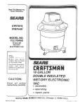
Models:
1480
lSeilalllumberc-1000
andabouel
1481
tSefialllumbers1000andabouel
*,[]finih** lrKUUI,
I S O1 3 4 8 5G E R T I F I E D
Foreword
..........1
......2
Definitions
PrecautionarySymbol
........3-4
S a l e tPyr e c a u t i o. .n. s.
.........5
Theoo
r yf0 p e r a t i .o.n. .
...... ..6-7
N o m e n c l a t .u. r e
..........8
Specifications..
... ....9-12
Troubleshooting
F l u i dSoo f t w a E
r er r o r M e s s a g. e s . . . . . 9
.....9
Eer rro r
Motor/Blow
.....9
nsorError.
T e m p e r a tSuer e
......10-12
FluidoSystemTesting
.........11
V i s u Ianl s p e c t i o n
........11
G r o u nRde s i s t a nTcees t.
.....11
L e a k aT
g e s t .s
R e s e t t iFnlgu i dFoa c t o rDye f a u l .t .s. . . . . 1 1
......11
P r e h e a t T .e s t
Diagrams
......23-45
- 120v
and230v
.. . .. .23
BaseAssembly
- l20vand230v ....24
Panel
Assembly
Control
. ... ....25
L i dA s s e m b- l1y2 0av n d2 3 0 v
........26
S w i t cPhl a t e A s s e m 1b 2l y0-v
- 230v
. . ... ...21
Plate
Assembly
Switch
........28
W i r i nD
g i a g r a- m
l20v
........29
W i r i nDg i a g r a- 2
m3 0 v
H e a t eErn c l o s uArses e m b- l1y2 0 v. . . . . . . . . 3 0
- 230v. . . .. . .. .31
Enclosure
Assembly
Heater
1 2b0l yv....32
Motor&SupportAssem
230v
....33
Motor& SupportAssemblyAgs s e m b( 1
l y)- l 2 0 v. . . . . . . . . 3 4
M o t oHr o u s i n
Ags s e m b( 1
l y)- 2 3 0 .v. . . . . . . . 3 5
M o t oHr o u s i n
(2)- 120v
.. . .. . . . .36
Assembly
MotorHousing
Ags s e m b l y-{223) 0 .v. . . . . . . . 3 7
M o t oHr o u s i n
M o t oH
r o u s i nAgs s e m b( l3y)- 1 2 0 .v. . . . . . . . 3 8
Ags s e m b l y-(233) 0 .v. . . . . . . . 3 9
M o t oHr o u s i n
.......12
TreatmentllmeTest
.. . ...40
F i n a l A s s e m( 1b)-l y1 2 0 v
.....12
A i rS p e eTde s.t
......41
.. ...12
FinalAssembly{t)-230v
C o n t rP
o la n eLlo c k - U p
.. . . . .42
Assembly
Final
. '....13-20
Procedures
{2)- 120v
& Replacement
Removal
......43
FinalAssembly(2)-230v
.....13
a sn dC e l l e x
Sleeve
......44
F i n a l A s s e m b l1
y (230)v....13-14
C o n t rP
o la n ePl CB o a r d
......45
.15-18
FinalAssembly(3)-230v
Heater
Fluido
....46
. . . . . . . . . 1 8 Warranty
F l u i dDoi f f u s e r
Repair
......46
Repair/Out
ofWarranty
. . 1 8 - 1 9 Warranty
F l u i dM
ootor
.....19
M u f f l e r aM
n du f f l e r C o v e r
P u l sMe o d e T e s t .
Casters
Parts
Replacement
cnliinJogi crout ot enc6re
.........12
.'.......20
....21'22
inthismanual.
contained
Precautions
andinformation
theSafety
Read,
understand
andfollow
Technicians,
approved
by
information
forthoseFieldService
safeg,andfieldservice
thenecessary
Thismanual
contains
1480and1481units.
DHTModels
fieldservice
ontheFluido
Group,
toperform
Chattanooga
duetocontinual
wascunent
anduptodate.However,
contained
herein
theinformation
Atthetimeof publication,
well
asChattanooga
Group's
as
knowledge
inthefieldoffluidotherapy,
clinical
andincreased
improvements
technological
periodic
changes
andimprovements
totheir
policyofcontinual
therightto make
Groupreserves
Chattanooga
improvement,
Group.
onthepartofChattanooga
without
anyobligation
equipment
anddocumentation
utilized
intheFluidoDHT
inthelatesttechnology
andtrained
to stayinformed
forfieldtechnicians
It is thesoleresponsibility
Service
significant
improvements
are
incorporated,
to
time,
as
Group.
From
time
Models
1480and1481unitsbyChattanooga
(wwwchattgroup.com)
manual
in
lieu
of
reprinting
a
complete
produced
our
web
site
available
on
and
made
Bulletins
willbe
improvements
totheFluido
information
andtechnological
service
prematurely.
willprovide
updated
Bulletins
TheseService
technicians.
service
forusebyapproved
DHTModels
1480and1481
"Approved
Defi
nitions;
Service
Technician"
1.Levell.
required
byChattanooga
theminimal
training
completed
thathavesuccessfully
Technicians
ThoseFieldService
techniques.
inbasicservice
Group,
as
LevelI Training
aswellasLevelll Training
completed
thathavesuccessfully
Technicians
2. Levelll. ThoseFieldService
andprocedures.
andrepair
techniques
troubleshooting
specific
to perform
required
aswellasLevellll
Levels
I & ll Training
completed
thathavesuccessfully
Technicians
3.Levellll. ThoseFieldService
TheTechnician
andRepair
techniques.
allnecessary
Troubleshooting
to perform
asrequired
Training
Advanced
should
havetheabilityto
withexperience
andcoupled
oftraining
thethreelevels
completed
successfully
having
fromChattanooga
Training
Materials
withthenecessary
inLevelI andLevelll Training
trainothertechnicians
Group.
maygranta
ofthetechnician,
experience
andbased
onknown
atitsdiscretion
Group,
4.Temporary.Chattanooga
"Temporary
unitrequiring
andrepairofa specific
troubleshooting
forparticular
to a fieldtechnician
Approval"
levelofa technician
thetraining
acknowledges
innofashion
Approval"
This"Temporary
attention.
immediate
fora specific
unitfora
situations
isutilized
onlyin unique
Approval"
This"Temporary
above.
asdefined
as
such.
and
is
documented
only
technique
service
specific
for
techniques
troubleshooting
therecommended
Group,
utilizedbyChattanooga
ofthetechnology
nature
Duetothecomplex
is
leveltroubleshooting
component
only.Noboard
replacement
andPCBoard
Board'
PCBoards
areio determine'Bad
leveltroubleshooting
AnyPCBoardcomponent
Group.
byChattanooga
or partsbesupplied
norwillinformation
recommended
performing
techniques.
suchtroubleshooting
Technician
oftheService
performed
willbeatsoleriskandliability
practitioner.
medical
ofa licensed
andsupervision
theprescription
istobesoldandusedonlyunder
Thisequipment
Service
Technician".
onlybyan"Approved
istobeserviced
Thisequipment
Contact:
Service
ForAdditional
Group
Chattanooga
Department
DHTSupport
TollFree:1-866-864-0598
0-7200
OutsideUSA:+1-423-87
GroupFluidoDHT Dry Heat TherapyUnit ControlPanel.Understandthe
The followingsymbolsare locatedon the Chattanooga
meaningoi eachsymbolbeforeattemptingany operationor use of the unit.
o
I
Thissymbolindicatestherapysessionllme
adjustment.
ThissymbolindicatestherapysessionTemperature
adiustment.
ffi
A
V
therapysessionAir Speed
Thissymbolindicates
adjustment.
in
Upwardadjustment
Thissymbolindicates
functionparameters.
in
ThissymbolindicatesDownwardadiustment
functionoarameters.
:iQ
light
Blueindicator
Thissymbolwiththe illuminated
changing.
the IntakeFilterrequires
indicates
ffi
Thissymbolwith the illuminatedBlue indicatorlight
indicatesthe Cellexomedia requireschanging.
o
o
This symbol indicatesStart therapy session.
This symbol indicatesStop therapy session.
rL__
This symbol indicatesPulse Mode for pulse
therapysessions.
\7
fnis symbolindicatesPreheatStandbyfunction.
2
Definitions
Precautionary
Symbol
found
this
Theprecautionary
instructions
throughout
byspecific
symbols.
manual
areindicated
before
symbols
andtheirdefinitions
Understand
these
Thedefinitions
of
thisequipment.
operating
orservicing
areasfollows:
these
symbols
precautions
thatmustbereadandunderstood
before
attempting
anyservice
techniques
ontheseunits.
will
Throughout
thismanual,
specific
safetyprecautions
Read,
understand
befound.
andfollow
allsafeg
precautions.
AcAurroN
AcAUTToN
CAUTION
p,ossible
willexplain
indicator
Textwitha "CAUTION"
to
infractions
thatcouldhavethepotential
safety
to
injuryordamage
to moderate
cause
minor
equipment.
AWARNING
WARNING
possible
indicator
willexplain
Textwitha "WARNING"
. Read,understand
andpractcehe precautionary
andoperating
insfuclions
foundinhis manual.
Knowhe limitations
and
wifr usinganyelectitaldevice.Observe
he
hazards
associated
precautionary
placed
andoperationaldecals
onhe unit
. DONOToperabhe unitwhenurrecbd b aryunitoherhat
Chatanooga
Awp devices.
. Refllunitddlyb propefl lq/d wih ChatiloogaGroupCdlef Dry
Heatlvledium.
. ChageCdlexDryl-leatlrediumewrysix(6)rnmts.
' UsemlyCdhxDryl-leatliledumlnhe Fhijofierqyunib.
. Clean
Inlet
befueunltsffilp.
ffis) daily
bopeatebubn
mntobm tpcond pa'd(s).
Useonlyfingens
b
otjecbsd aspernbc perswilreulth danage
Useofsharp
tp unil
. Tumunitb tre "SHrdWnpdebebrepcrtbnlnga paliertor
he unil
rennving
a palientfrun
. Afterq betrween
teatrpnb,donotinrnediably
unph.g
u trm te
polerofifromfte unilAlbtltp unitbpooesstrtulghhe "Cod
Do,vn'clrh.Theunitqpesinb sbt&y npdeder teatnenttirne
t'e
hasdaped.Shdby cat bedsded ry gessing
p$eabbhrdbybubn.Theunitgoes
toa 3 mhutecoddo\ilnmode
te pouuofibefore
coddoiln
ofi.TumirB
aftershrdbyb hrmed
hazardotts
b te eqiJipntent
andmuHled
cornftbs's pobnlidly
b he
hatpoarer
becJppl[ed
b hilureofhe unilltisreconrnended
featnent€f
unilatd lirnesKeepinmhdftattp rcccnmended
speedis50%
. Seared antyporbbefore
trrnlq trc unitOt'I.
. Check
b enue coned
unitHnperafure
bebrefeatngpat*mt
temperabre.
. Plm he patient
poilirnallo\t'/ing
ftr coned
ina comforbUe
being
feabd.
|imb
flacanentofhe
. Propastragead hasput temperafures
fu he FluijoDHT
'C
Relatire
HumUity
85%.
unibae 40"F- 158"F(4.5 - 70"C).
. Thisequisnentgenerates,
usesandcanradiabradbfreqlency
andusedinrordarce wihhe
energy
and,ifnotinsblled
in
b otterdevices
interference
maycausehannful
instuctons,
will
hatinterference
frereisnoguarantee
Holwver,
fre vicinity.
interfsence
tooher
Harmful
notooqlrina patfula installatin.
hisequippntmad 0fi.
bytuming
canbedetermined
devices
usingonea rnseofhefollowing:
Trytomnedte interfaence
cause
serious
thatwillpotentially
infractions
safety
damage.
andequipment
injury
DANGER
possible
willexplain
indicator
Textwitha "DANGER"
hazardous
thatareimminenfly
safetyinfractions
thatwouldresultin deathor seriousinjury.
situations
HMARD
EXPLOSION
of
inthepresence
Donotusethisequipment
isalso
Thissymbol
anesthetics.
flammable
plate
number
of
prominently
ontheserial
displayed
theunit.
NOTE:
'NOTE"
maybefound.
thismanual
Throughout
information
toaidinthe
arehelpful
TheNotes
described.
being
particular
areaorfunction
heseparati,on
device,
increase
frereceMng
orrdocab
Reodent
a
toanouteton
mtnedhequiprnent
freequipnenl
betr,rrcen
aremnneded
fromtrattowtridtreofrerdevice(s)
difierent
circuit
fu help.
tedn'rcian
treffioryfieldservice
and/or
consrlt
SafetyPrecautions
precautions
allsafety
andfollow
understand
Read,
safe$
aregeneral
Thefollowing
found
inthismanual.
3
Continued
SafetyPrecautions
AWARNING
. Explosion
if usedinthepresence
of
hazard
flammable
anesthetics.
Thewaming
symbolfor
is prominently
displayed
ontheserial
thishazard
plate.
number
. Federal
tosaleby,oronthe
thisdevice
lawrestricts
practitioner.
physician
This
licensed
or
orderof,a
under
the
continued
beusedonly
device
should
practitioner.
orlicensed
supervision
ofa physician
o Forcontinued
protection
replace
firehazard,
against
fusesonlywithonesoftheconecttypeandrating.
grounded
. Make
by
theunitiselectrically
certain
grounded
service
electrical
onlytoa
connecting
and
national
totheapplicable
receptacle
conforming
localelectrical
codes.
. Thisdevice
bekeptawayfiomchildren.
should
. Caremustbetakenwhenoperating
thisequipment
or
electromagnetic
Potential
around
otherequipment.
to
the
other
couldoccurtothisor
otherinterference
bynot
thisinterference
equipment.
Trytominimize
with
it.
inconjunction
usingotherequipment
you
. Before
toa patient
anytreatment
administering
withtheoperating
acquainted
should
become
as
available,
procedures
foreachmodeoftreatment
and
wamings
mntraindications,
wellastheindications,
foradditional
precautions.
otherresources
Consult
ofDryHeat
theapplication
regarding
information
Therapy.
. Toprevent
theunitfrom
disconnect
shock,
electrical
anymaintenance
attempting
before
source
thepower
procedures.
. UseonlyCellet'processed
intheunit
dryheatmedium
dusting.
to prevent
excessive
. Adequate
precautions
betakenwhen
should
or diagnosed
withsuspected
individuals
treating
suchasheart
ordiseases
conditions
medical
problems,
etc.
diabetes,
epilepsy,
professional
o Priorto treatment,
a medical
consult
to be
measures
familiar
withtheprecautionary
allergic
thatmayexperience
takenforpatients
reactions
todustandpollen.
. Properly
to National
according
ofusedCellex
dispose
andregulations.
rules
andlocallaws,
. Perform
Maintenance
asdescdbed
inthis
allRequired
to
Required
User
Manual.
Stict
adherence
he
andhe
Failure
fortheFluidoDHTunitsismandatory.
Maintenarrce
Maintenance
theRequired
muldresuhinhe
to perform
ofhe unit(s)
entering
theheatchamber
Cellexmedium
andcausesevereinjuryto patienbaslvellassmoke
tohe fmilityandhe Fluido
DHTunit(s).
damage
. tr/akecertain
tre unitburplugged
fruntp por,rerso.rrce
before
atemplirganyrcnnvdad redrcernentproedures
mtpunit
4
a heating
across
airisdirected
Thepressurized
blower.
itviaanintemal
airandpressurizes
ambient
DHTutilizes
TheFluido
through
across
and
diffused
pressurized
is
then
air
The
heated,
temperature.
treatment
theairtothedesired
bringing
element
parameters;
temperature,
speed,
air
patient
All
treatment
reservoir.
treatment
andheattheCellexmediain a
a baffletoRu]Oiie
TheFluido
withthetouchpaneluserinterface.
bytheoperator
arepiogrammed
settings
timeandtheun1preheat
treatment
ofthe
and
rotation
height
lifttoadjust
hydraulic
operated
cistersanda manually
fourlocking
DHTunitbaseincorporates
comfort.
forpatient
reservoir
treatment
5
FluidoDHT
the
graphics
below,Figure3.1,indicate
Thenomenclature
of theFluido
general
of themajorcomponents
locations
DHTunit.
beforeperforming
andtheirfunctions
Knowthecomponents
DHT
to theFluido Model1480
of or service
anyoperation
unit,
and1481
. Adjusts
and
CYLINDER
ADJUSTMENT
9. ELEVATION
patient
comfort.
for
height
desired
to
reservoir
maintains
10.UNITBASE- Rigidunitbaseforeaseintransporting
fortreatment.
locations
unittodifferent
PEDAL'Usedto raise,rotate,
ADJUSTMENT
11.HEIGHT
of
adjustment
forheight
andlockthecylinder
release
theunit.
Motor.
Blower
Houses
HOUSING.
12.BLOWER
SeePage7 for
Controls.
PANELOperator
13.CONTROL
ofeachcontrol.
description
detail
WINDOW'View
VIEWING
CAVITY
14.TREATMENT
treatment.
area
during
treatment
portwith
access
PORT- TopTreatment
15.TOPACCESS
sleeve.
tothetreatment
access
LID- Allows
1 . RESERVOIR
Cellefmedium'
cavi$foradding
Lid
Reservoir
Secures
2. LATCHES
' Fouravailable
SideAccess
PORTS
3. SIDEACCESS
unit.
of
the
end
Twooneach
Ports.
nt
treatme
MENTCAVITY'Patient
R|IREAT
RESERVOI
Reservoir.
andCellex
cavity
and
Replaceable
SLEEVES'
LIMB
TREATMENT
sleeves.
patient
limbheatment
launderable
element.
Heating
Houses
CHAMBER'
6. HEAT
periodic
Requires
filter.
Airintake
FILTER.
7. INTAKE
replacement.
for
Casters
Locking
CASTERS'Four
LOCKING
fortreatment.
theunitinplace
securing
6
FluidoControlPanel
graphics
below,Figure
TheControl
Panelnomenclature
of theFluidoDHT
andfunctions
thelocation
3.2,indicate
Model1480and1481controlpanel.
beforeperforming
andtheirfunctions
Knowthecomponents
DHT
oforservice
totheFluido Model1480
anyoperation
unit.
and1481
3
4
Tumthe PreheatStandbyMode
STANDBY6. PREHEAT
desiredfor
OnandOffas wellas settheparameters
start.
Modeto automatically
Standby
thePreheat
STOP-Pressto stoptreatment.
7. TREATMENT
STARTPressto startheatment.
8. TREATMENT
Usedto tumoffmaintenance
9. CLEARBUTTONhasbeenpropedy
aftermaintenance
indicators
andoperational
settings
Displays
DISPLAY1 . PANEL
parameters.
withtheUpand
Usein conjunction
TEMPERAIURETemperature.
tosetoperation
Down
anows
The
inf increments.
canbeadjusted
Temperature
is88' Fto 130'F
range
temperature
available
(31'Cto54'C).
withtheUpandDown
Useinconjunction
AIRSPEEDoftheCellexe
arowsto adjustairspeedforfluidization
(in
from5%to 100%
range
speeds
Available
Medium.
5%increments).
TurnPulseModeOnandOffaswellas
PULSE
MODETimeisfrom1
Pulse
pulse
time.Available
adjust
On/6Seconds
Offto6 Seconds
0n/1Second
second
0ff.
performed.
'10.MEDIAthe
willlightwhenit is timeto change
Indicator
CellefMedium.
the
willlightwhenit is timeto change
lndicator
11.FILTERfilters.
required
withtheUpandDownanow
12.TIME-Useinconjunction
timeis 1 to99
Available
time.
tosettreatment
buttons
orContinuous.
increments,
inoneminute
minutes,
with
inconjunction
ARROWS'Use
5. UPandDOWN
to setdesired
buttons
othermodeor function
parameters.
7
Model 1481
Model 1480
Continuous
. . . . . C o n t i n u o u sMODE0F0PERAil0N....
M0DE0FOPERAil0N.....
FUNCTIO.hIS
OPffiATIOMI
RJNCTIONS
OPERANOMT
andAirSpeed
Variable
Adjustnents . . .llme,Temp
andAirSpeed
Adjus[nents . .llme,Temp
Variable
to
6 Sec0N/0FF
.
.
OFF
Mode.
hrlse
to
6
Sec
0N/0FF
.OFF
.
tulseMode
(See
10)
Page
Board
Languages
on
languages.
9
Arailable
and
French
Spanish
.
English,
languages.
AraihUe
andContinuous
andContinuousTRFATMENTTIME.. 1to99minutes
TREATMENTnME.. 1to99minutes
*OPERATING
3l "C(88"F)to 54oC(130'F)
TEMPERAruRE.
88"F(31"C)to130'F(54'C) *0PERATING
TEMPERAruRE.
(5%increments)
(5%increments)AIRSPEED.
. . ..5%to100%
to100%
....5o/o
AIRSPEED
llMER.. . . . Perdefaultsettingwith50%Air Flow
. . . . Perdefaultsettingwith50%AirFlow PREHEAT
PREHEATIMER.
then5%
30min.preheat
during
then5%
30min.Preheat
during
standby.
airflow
for
forstandbY.
airflow
lbs)
(9-11
MEDIUM
CAPACIIY . . . . . 9-11ks(20-25
kg) Cellexo
CAPACIIY . . .. .20'25lbs
CelfefMEDIUM
10A
Hz,
230
V-,
50/60
P0WER
. . . 120V50/60Hz,12A NRII
NRtr Povr/ER
....10Allm eDel ay ( Sl o- Bl ow )
RJSERAIING
....l 0A T i meD el ay( Slo- Blow)
R J SE R A T I N G
DIMENSIONS
PHYSICAT
n{YSICAL
DIMENSIONS
....79cm(31")
.....31"(79cm) UnitDeptr.
UnitDeptr
.
. .75cm(29.5")
(75
UnitWdtr
cm)
..
.29.5"
UnitW'rrltr.
124
cm(41"- 49")
.
104
cm
(104
Height
O,nerall
cm)
124
cm
49"
.
41"
&erafl Height
. . . 79cm 99cm(31"- 39")
htientHeight
. . . 31"- 39"(79cm- 99cm)
Height
Patient
.....360o
HeseryoirSwivel
......360'
B e s e r u o i r s wi ve l
(145
lbs)
kg
.
.
.
.66
Weight.
....1451bs(66kg)
Weight
(210
lbs)
(lncluding
kg
.
.
95
(95
Stool)
Weight
Shipping
(lncluding
. 210lbs kg)
.
Stool)
Weight
Shipping
I
Class
ElecuicaL
I
Class
Electical:
^
t*
.fi.t* Bftuipment
BEquipnent
documentation.
accomparrying
consult
A Attention,
of
ingress
to preYent
Notdesigned
equipment
Ordinary
water.
*Dependent
selected
airspeed
upon
documentation'
accomparrying
consult
A Attention,
prevent
of
ingress
to
designed
Not
equipment
0rdinary
water.
*Dependent
selected
airspeed
upon
8
FluidoDHTModel1480and1481Softwaretrror
Messages
providedin this sectionis
A. Theinformation
DHT
the Fluido
intended
to aidin troubleshooting
Thereareonlytwo
Model
1480and1481units.
a
thatcouldindicate
errormessages
software
"Bad
shouldtestscontained
Therefore,
Board".
the pc boardis badthe
inthissectionindicate
No
as an assembly.
boardmustbe replaced
g information
is
componentleveltroubleshootin
Group
for
by Chattanooga
orwillbe provided
of pc boardcomponents.
fieldtroubleshooting
a n da l lm a i n t e n a nacnedr e p a inr e c e s s a r y
beforetheunitis placedbackintoservice.
Referto theappropriate
sections
of this
m a n u a l f oprr o p erre m o v aaln dr e p l a c e m e n t
procedures.
Temperature
SensorError
A. Should
Sensorexperience
theTemperature
problems
will display
fourdashes
thesoftware
"Temp"
beneath
ontheLCD.
as bad,
B. Oncethe PCBhasbeendetermined
inthe
boardas described
replace
thesuspected
sectionof thismanual.
& Replacement
Removal
Motor/BlowerError
the softwaredetecta problemwithinthe
A. Should
the displaywill
of the Blower/Motor,
operation
"AIRSPEED"
onthe
showfourdashesbeneath
panelLCD.
control
"Lock
may
Up,"
Should
thisoccurthesystem
preventing
of the unit.This
anyfurtheroperation
errorcouldbe causedby severaldifferent
problems
including:
oTheintakefiltersareclogged
andrequire
cleaning.
r TheTemperature
Sensoris faultyandrequires
replacement.
o TheDistributor
is clogged
andrequires
changing.
. TheCellex
hasentered
the heat
Medium
the airflow.
cavityof the unitandis restricting
byturningthe
Sensor
B. ResettheTemperature
"Stop"
buttonfor
unit0ff. Pressandholdthe
"Stop"
Release
the
seconds.
tento fifteen
buttonandturntheunit0n.lt will be necessary
lf the
to resettheClock(referto UsersManual).
persists,
replace
the
remove
and
Error
to
lf theproblem
continues
Sensor.
Temperature
pc
in
persist,
the board the control
replace
sectionof this
panel.Referto theappropriate
m a n u a l f oprr o p erre m o v aaln dr e p l a c e m e n t
procedures.
therecouldbeseveral
is visible,
B. lf thisindicator
possible
reasons:
.The intakefiltersareclogged
andrequire
cleaning.
a
oThemotorhasoverheated
andrequires
period
is
resumed.
operation
before
cooling
.The Distributor
andrequires
is clogged
changing.
oTheCellex
theheat
Mediumhasentered
theairflow.
is
restricting
cavityof the unitand
the
remove
bevisible,
Should
thisindicator
any
Perform
unitfromserviceimmediately.
I
Testing
FluidoDHTSystem
A General
is intended
to aidin
information
1-Thefollowing
of the
themajorcomponents
troubleshooting
"Board
testsare
only.These
Level"
DHTUnitsto
procedures
andmethods
testing
OEMstandard
shipment
of anyFluido
before
usedat thefactory
unit.
natureof thetechnology
2. Dueto thecomplex
therecommended
Group,
utilized
byChattanooga
"Bad
techniques
aret0 determine
troubleshooting
only.Noboard
Board"
andboardreplacement
is recommended
leveltroubleshooting
component
by
or partsbesupplied
norwill information
level
Anyboardcomponent
Group.
Chattanooga
performed
will beat soleriskand
troubleshooting
performing
such
Technician
liabilityof theService
techniques.
troubleshooting
asbad,
3.0ncethePCBoardhasbeendetermined
Chattanooga
Group
theboardonlywith
replace
parts
hardware.
OEMreplacement and
Fxbres& MaterialsBequired
B. SpecialTools,
tools
theuseof special
testsrequire
l. Certain
will belistedat theparticular
These
andfixtures.
Testing
withany
testwheretheyarerequired.
toolorfixtureotherthanthose
otherspecial
readings
ortest
statedcouldgiveenoneous
perform
asstated
tests
exactly
the
Always
results.
results.
accurate
to ensure
will belistedfor
settings
testequipment
2-Standard
performing
performed
thetest
to
aid
in
eachtest
proper
readings.
andensure
t0 OEMstandards
DHT
andrepairof theFluido
3.Thetroubleshooting
onlybyauthorized
beperformed
units,should
byChattanooga
andcertified
trained
technicians
Group.
C. ftuipmentBequired
Multimeter
1.Digital
(Hi-Pot)
andground
Withstand
2-Dielectric
tester.
resistance
Meter.
3. Milliohm
4. Calibrated
Thermometer
StooWatch
5. Calibrated
ACAUTION
compound
Thefollowing
tool,lubrication,
andsealing
removal
and
to thecomponent
requirements
arecritical
of theFluido
DHTunit.
replacement
the
nutsandscrews
usedto assemble
All hardware,bolts,
Dueto thesizeof these
DHTareSAEStandard.
Fluido
is available.
Therefore,
nometricequivalent
components
to obtain
theproper
sizetoolsfor
it will benecessary
of certain
components.
removal
andreplacement
compounds
listedbeloware
andsealing
Thelubricants
components
to ensure
in theassembly
of certain
crucial
patientsafetyandefficient
operation
of theunit.Useonly
products
listedoranapproved
therecommended
possessing
thesameproperties
andqualities.
equivalent
6.Required
SAETools
#1Phillips
Screwdriver
#2Phillips
Screwdriver
1/2,5/32,and11/32Wrenches
5116,7
/16,9116,
(ordrillbits)
1/8and5/32AllenWrenches
UtilityKnife
Vacuum
WeVDry
Lubdcanb
7.Bequired
grease.
based
multipurpose
Silicon
Sealing
Compound
8.Required
puresilicon
sealant
100%
NOTE
will
requirements
Thetool,lubricant
andsealing
compound
removal
andreplacement
belistedattherespective
procedures
throughout
thismanual.
NOTE:
faultwith
testerto indicate
Withstand
AdjustDielectric
test
whenat specified
theoutput
120kOhmLoadacross
voltage.
10
VisualInspection
A General
DHTunit.A visual
theFluido
Visually
inspect
Technician,
inspection
can,to anexperienced
possible
of theunitand/orinternal
indicate
abuse
problems.
Test
Ground
Besistance
A Voltage
Specifi
cations
Hz,40Watts
i/odel14$ . . . . . Input:120VAC-50/60
230VAC-50/60
H2,40
Watts
Model1481. . . . Input:
B. Specificatiur
Resistance:
500milliohms
Acceptable
Maximum
Required
C. Equipment
Milliohm
Meter
D. Test
Place
unitonlevelworksurface.
prongof power
Place
onemeterprobeontheground
metalorscrewon
cordandtheothert0 anyexposed
theunit.
Leakage
Tesb
.....1000V
Tes'tVolbgespec
per
leakage
testsasrequired
Conduct
allnecessary
"Chapter
orlater,
Equipment"
of the1999,
7 Electrical
(National
FireProtection
of theNFPA
edition
"Health
standards.
CareFacilities"
Association)
Besetting
Fluido
DHTFactory
Default
Settings
Toreset
allfactory
default
settings
oftheunit,turnunit
"Clear'
Off.Depress
andholdthe
button
onthecontrol
panel
andturnunitonsimultaneously.
Preheat
Test
A Tools& Equipment
Bequired
ibrated
Cal
Thermometer
B.fteheatTestProcedures
Power
Requirements:
Model1480.
...120VAC
Model1481
....230VAC
grounded
Plug
theunitpower
cord
toa
electrical
service
receptacle
conforming
totheapplicable
national
andlocalelectrical
codes.
Tumunitpower
On.
switch
Startthepreheat
function
bydepressing
the
"PREHEAT
STANDBY"
buftononthecontrolpanel.
Afterapproximately
30seconds,
theBlueLED
should
illuminate.
30minutes
orless,depending
Afterapproximately
the
ambient
temperature
of
the
medium,
onthe
from50%airspeed
to 5%
blower
should
reduce
indicator
should
readthe
airspeed
andtheTemp
Insertthe
temperafure
of theCellex"
medium.
intomediumandrecordthe
calibrated
thermometer
reading
shouldbe+ 5 "F
reading.
TheTemperature
'C
or 3 of Specbelow.
'C)
'F
Default
Temp.Spec. . . . 115 (46.11
Preheat
range
reading
outside
thespecified
A temperature
intakefilters,
clogged
byclogged
maybecaused
sensor,
faultytemperature
orfaulty
distributor,
for
section
heating
Referto theappropriate
element.
procedures.
andreplacement
theproperremoval
AWARNING
AND/ORLEAKAGE
WITHSTAND
DIELECTRIC
UNITFAILING
SYSTEM
INTERNAL
SERIOUS
TESTS
INDICATE
COULD
PROBLEMS.
SENDUNITTO
DONOTPLACE
UNITBACKINTOSERVICE!
FACTORY
FOR
REPAIBI
!
INTHEFIELD
TOREPAIR
DONOTATTEMPT
11
Pulse
Mode
Test
A Tools
& Equipment
Bequired
Calibrated
StopWatch
B.fulseModeTestftocedures
Reset
thefactory
defaults.
Refer
tothesection
"Besetting
entitled
Fluido
DHT
Factory
Default
page
Settings"on 11.
Press
theBlueLED
the"PULSE
MODE"
button,
should
illuminate.
Press
the"TBEATMENT
STABT"
button.
Using
timethepulses
thecalibrated
stopwatch,
of
theunitwhileit isrunning.
Record
thereadings
taken
youentered
andverify
thesettings
forthepulse.
pulse
fourseconds
Theunitshould atapproximately
on,afterreaching
itsmaximum
blower
speed,
and
fourseconds
off.
Treatnentlime
Test
A Tools& ftuipmentBequired
Calibrated
StopWatch
B.Treatnent
TimeTest
the"Time"
Withtheunit0n,press
andrelease
thetimeto
button.
thedownanowadjust
Using
"1:00".
"TREATMENT
Press
START"
andtimewiththe
Record
thereading.
Calibrated
StopWatch.
l minute+lsecond
TrcatnentTimeSpec
AirS@ Test
Airs@ TestPrmedures
"Treatment
Whileunitis
Start".
Turn
unit0n.Press
"Air
press
button.
UsetheUp
the
Speed"
running,
theairspeed
to 1007o
to adjust
andDown
arrows
fortheincrease
and
andback
downto 5%.Listen
Look
for
increased
the
blower
speed.
decrease
in
inthe
ofthemedium
anddecreased
fluidization
reservoir.
Contolhnel Lock-up
panel
Upandnotallowany
Lock
Should
thecontrol
Reset
the
changes.
operation
oftheunitorparameter
(Befer
tothesection
entitled
unit
Factory
Defaults
"Besetting
Default
Settings"on
DHTFactory
Fluido
persists.
page
replace
theControl
11).
lf thecondition
Panel
PCBoard"
on
to "Control
Panel
PCBoard.
Refer
procedures.
page
replacement
13forremovaland
NOTE:
oftheunitparameters
andsetting
Forproper
operation
Manual
refer
totheUser
Defaults.
outside
theFactory
DHT.
fortheFluido
12
theBezelfromtheControl
remove
2.Carefully
Panel.
Sleeves
andCellex'
AWARNING
BEFOBE
SOURCE
THEPOWER
UNPLUG
THEUNITFROM
ORREPLACEMENT
ANYREMOVAL
ATTEMPTING
FOLLOW
SHOCK.
ELECTRICAL
TOPREVENT
PROCEDUBES
TO
FOR
GROUNDING
PROTOCOLS
BEPAIR
ELECTBONIC
COMPONENTS
TOTHEELECTRONIC
PBEVENT
DAMAGE
ICITY.
FROM
ELECTB
STATIC
Refer
to theFluidoDHTUserManualfortheproper
items:
of thefollowing
andreplacement
removal
UnitEndSleeves
UnitTop
Sleeves
Cellex
Medium
lntakeFilters
ContolPanelPCBoard
Required
A Tools& Equipment
SmallFlatBladeScrewdriver
5/160penEndWrench
Screwdriver
#2Phillips
tre ContolPanelPCBoard
B. Removing
thethreeretainingscrewsfromthe
1.Remove
PanelBezel.
Control
the
nutssecuring
thefourretaining
3.Remove
on each
base(trruo
ControlPanelto its mounting
side).
13
4.Remove
the Control
Panelfrom
themounting
base.
C. Replacing
fre ConfolPanelPCBoard
panelPCboard,reverse
Toreplace
thecontrol
"Removing
steps1 through
7 of
the Control
Panel
PCBoard"starting
onpage13.
NOTE
Keepin mindthefollowing
when
replacing
theControl
PanelPCBoard:
r Attachtheconnector
withthetwo
brownwiresto theheaterterminal.
. Attachtheconnector
with onebrown
wireandonebluewireto theline
terminal.
o Attachtheconnector
with oneblack
wireandonewhitewire to the motor.
o Attachthesmall,three-wire
to thespeed
connectorwires
terminal.
. Attachthesmall,two-wireconnector
to thetemperature
terminal.
fromthePC
thefivewiringharnesses
5.Remove
Board.
14
Heater
Fluido
to thecontrol
closest
tubinsert
therubber
5.Remove
tubinsert.
panel.
theotherrubber
Then,
remove
Required
A Tools
Vacuum1/BAllenWrench.
Wet/Dry
.
Screwdriver
7/16Wrench #1Phillips
WireCutters Hammer
Heater
fte Fluido
B.Hemodng
fromunit'
lidcompletely
1.Bemove
from
theCellex
remove
vacuum,
thewet/dry
2.Using
thetub.
fromtheperforated
screws
theseven
3.Remove
the
of tub.
metal
atthebottom
AcAurloN
thescrewheadsat thebaseof
to vacuum
Makecertain
will notfallinthe
thatCellex
thetub.Thiswill ensure
of
holes,andyouwill notroundouttheheads
standoff's
them.
whenre-inserting
thescrews
remove
thenewly
6.Usingthewet/dryvacuum.
Cellex.
exposed,
excess
AcAUrtoN
fromtheheadsof
theexcess
Cellex
Makesureto remove
outtheheads
of the
thehexscrewsto avoidrounding
SCTEWS.
fromthebottomof the
thetenhexscrews
7.Bemove
tub.
thenewly
remove
4.Usingthewet/dryvacuum,
Cellex.
excess
exposed,
notto
becareful
vacuuming,
NOTE When
sensor.
thetemPerature
damage
(andfinal)pieceof perforated
12.Remove
bottom
metal.
theground
screw.
remove
13.Usingthescrewdriver,
the
bandsecuring
theplastic
B.Cutandremove
sensor.
temperature
metal.
theperforated
9. Remove
'lO.Remove
baffle.
thediffuser
foam.
thediffuser
11.Remove
14.Follow
steps1-3listed
in "Removing
theMuffler
"
Cover
andMuffleronpage
19.
lS.Remove
thetwohexscrews
fromthemotor
support
bracket.
ir GAUTION
Makecertain
thatyoudo notspillanyCellexintothe
heaterenclosure
cavity.
16
16.Using
wrench,
thef ivehexnuts
a 7 116
remove
fromtheheater
housing,
aswellasthemotor
support
bracket.
l9.Using
wirecutters,
cutthewirebetween
the
brownandblack
wires.
20.Unplug
thedarkbluewirefromtheinletsideof
thelinefilter.
theclawendof thehammer
17.Use
to gently
and
pulluptheedgeof theunitin orderto get
slightly
21.Using
thewirecutters,
cuttheblackheater
indicator
lightwirefromtheswitchplate
assembly.
18.Slide
theheater
assembly
out.
17
fie FluidoHeater
C.Replacing
theFluido
to replace
attempting
NOIE: Before
thatmay
anylooseCellex
Vacuum
heater,
orheater
bein themotorhousing
housing.
steps1 t!ryuqh
reverse
theFluidoheater,
Toreplace
15-17
onpages
Heater"
theFluido
21of"Bemoving
or
solder
(i.e.,
wires,simply
of cutting
instead
them).
reattach
besure
heater,
theFluido
NOTE: Whenreplacing
(141
19).
to usea newdiffuser
holdthemotorwhileusingyour
2.Withonehand,
themotorwiringfromthe
otherhandto disconnect
2 figures.
harness.
Seethefollowing
FluidoDiftser
A TmlsRequircd
Screwdriver
Vacuum #2 Phillips
WeVDry
7/16Wrench
WireCutters
fte FluidoDiffuser
B.Hemodng
steps1 - 13
following
theFluidodiffuser,
To"Removing
remove
pages
1S16.
Heatei'on
theFluido
of
Diffuser
tre
Fluido
C.Replacing
steps1 tryqu_gh
reverse
theFluidodiffuser,
Toreplace
"Bemoving
1S16.
onpages
Heater"
theFluido
l3 of
FluidoMotor
A ToolsBequired
#2Screwdriver
the FluidoMotor
B.Bemwing
you
motor,
theFlui{o
to remove
Before
attempting
"Removing
the
3 of
1 through
st-eps
mustcompleie
onpage19.
andMufflerCover"
Muffler
of themotor
thefivescrewsoutside
1.Remove
plate,beingsureto holdtheplatewhile
support
thelastscrew
removing
CAUTION
themetalshaftontheendof
Becarefulnotto damage
figure.
Seethefollowing
themotor.
tre Fluido
Motor
C.Beplacing
Motolreverse
steps
1 and2 of
theFluido
To
replace
"Removing
onpage18
theFluido
Motor"
3.Remove
thefoaminsertfrominside
themuffler
cover.
theholein thefoaminsert.
NOTE Notice
You
will needto lineupthisholewiththe
Morris
taperontheshaftwhenyou
re-assemble
themuffler.
Muffierand
MufflerCorer
Bequired
A Tools
Wrench
1/8Allen
B.Hemwing
tre MufflerCorcrandMuffler
themuffler
thatsecure
the14screws
1.Remove
cover.
fie MufflerCorerandMuffler
C.Replacing
Toreplace
themuffler
andmuffler
cover,
reverse
steps1-3of "Removing
theMuffler
Cove/'
onthis
page.
2.Slidethemufflercoverdownontheshaft.
19
Casters
andToolsBequired
A Materials
9/16Wrench
- 14135
{4)Caster
14104
Base
Frame(4)3/8-16
Nuts- 14146
Black
Acorn
theCasers
B.Bemoving
the
bypressing
arelocked
1.Make
surecasters
Thiswill
metal
flapuntilthewheeldoesnotmove.
prevent
while
frommoving
theshaftofthecaster
youareattempting
to remove
it.
2.Remove
eachof thefour3/8-16blackacornnuts.
eachof theshaftsof the
3.Liftthebaseto remove
fromtheunit.
fourcasters
fte Casten
C Replacing
to
1.Makesurecasteris lockedbeforeattempting
install.
and
2.Place
onecasteroneachcomerof thebase,
withfour3/8-16blackacomnuts.
attach
20
't4105 BASEASSEMBLY
FLUIDOTHERAPY
14206 -IARNESS
RECEPTACLE
TO POWERSWITCH
14111PATIENTTUB LID FLUIDODHT
14113LIDLATCHFLUIDODHT
14207 IARNESSO.T.TO STATH.E.
't4208 -IARNESS
MOTORSPEEDCONTROL
14116SCREW
#2X318PANHD.PHIL.
14209 -INE FILTERBRACKET
14117 DISTRIBUTOR
PLATEFLUIDODHT
14211 JARNESSCONTROL
INTERCONNECT
_\
14118PLEXTGLASS
TR|MFLUTDOTHEMPY
14213 ..IARNESS
GROUND7"
.\t\
14119 FoAMDrsrRtBUToR
eLATEFLUtDorHEMev
14214 {ARNESSGROUND24'
14120 TUBDRAINPLUGFLUIDOTHEMPY
14215 -IARNESS
TEMPSENSOR
14't22 632X112 OD X1 LG CERAMICSTD.OFF
14219 1I4.2OX 5/8 SANDWICHMOUNT
14123 632X1t20DX1-1t2 LGCERAMTC
STD.
14220 10 x24INSUI-ATION MOTOR HOUSTNG
14't24 GASKETTUB LID FLUIDOTHERAPY
14221 '' X 4" INSULATIONMOTORHOUSING
14125 MANUALUSER FLUIDOTHERAPY
14222 5'X 5" INSULATIONMOTOR HOUSING
14128 UANUALSERVICEFLUIDOTHERAPY
14't30 SLEEVE
ASSEMBLY
FLUIDODHT
14223 i. X 9' INSULATIONMOTOR HOUSING
't4225 JARNESSFUSE
TO POWERSWITCH22OV
14135 ]ASTERTENTE006874FLUIDODHT
14226 {ARNESS POWER SWITCHTO LINE FILTER
1 4 1 3 6 :OAM MUFFLER FLUIDO DHT
14227 -IARNESSO.T. STATTO H.E.
14137 VUFFLERCOVERFLUIDODHT
14228 -IARNESSLINE FILTERGROUNDTO CHASSIS
1 4 1 3 93OTTOMW/ MOTORHOUSINGFLUIDODHT
14229 =LBOWSLEEVE
ASSEMBLY
t4't4s
14230 NLETFILTER191551<22
[,r.7
J.I. DISPLAYLENS FLUIDODHT
r 4 1 4 6 qCORNNUT FLUIDODHT
't4148 SCREW1O-32x3/4 BUTT.
HD. SOC
't4150 SCREW10.32X1 BUTTHD
SOC
14231 :ILTER NYLON MESH 3-5/8" SQ.
14232 3LIDEETS32 X 50 D80153
14233 JSER INTERFACEBRACKETPAINTED
1415'l SWITCHPLATEGASKETFLUIDODHT
1 4 1 6 0 SCREW1O-32
X 'II2BUTr HD SOC
14161 IEX STANDOFF432 X .875ALUM.
14162 !,ULITSTACKADAPTER
1423/. \4OTORHOUSINGSUPPORTPAINTED
14235 :-OAMINSERT
r{.
1 4 1 6 6JSERINTERFACE
COVERFLUIDODHT
r{
v
1 4 16 8 )LASTICCOVERFLATFLUIDODHT
1 4 1 6 9 SLEEVERETAININGCLIP FLUIDODHT
14170 )OWERCORD FLUIDODHT
14171SWITCHPLATEFLUIDODHT
1418r'.rOP HEATERSHIELDMETAL
14238 SPACERNYLON112ODX1I4lDx 5/8 946394143
14239scREW#1 X 3/8'90253A033
(
t
f\
14240 EOP RIVET 1/8 X 5/8 ALUMINUM97447A135
14241 SAPTIVESTUD6/32X 3/8 93580A016
(-Y 14244 RtvNUT1G,32S10P175
't4245 STMIN RELIEF
PLATEFLUIDODHT
14174SASKET
MOTORMOUNTING
PLATE
14175ELBOWSLEEVEFLANGEFLUIDODHT
14236 MOTORSUPPORTPLATEPAINTED
- 14237 sETSCREW
s32X3t4 91375A151
.(_
I
14247 230V.MOTORHOUSING
ASSY.
14251 HYDRAULTCLtFT (CHROME)4500
1 4 1 8 5BOTTOMHEATERSHIELDMETAL
14253 FUSEHOLDER
SCHURTER.IN5C CO'ri<(
1 4 1 8 8 SPONGE
GASKET3/4"X1/4'ADHES.
14254 INLETAC FASTCONNECT
1 4 1 8 9 HARNESSCONTROL POWER SWITCH
14255 10AMp.sMMX 20MM(FUSE)220V
3 AG SLOWBLOW
14202 IARNESS CONTROLTO HEATERSUB
14259 2-56X 1/4" PAN HD.PHILPLT.
14203 IARNESS HEATERTO INDICATOR
14260 VOTORASSY.120V.
14204 HARNESSFUSE TO RECEPTACLE
14261 VOTORASSY.230V.
21
bO
lo
't4262 -IARNESSRECP. TO SWITCH PLATE
14263 IARNESSRECP.GROUNDTO GROUND
14265 1000watt110voltheater
14266 1000watt 220 volt heater
14268 rOPDIFFUSER
FLUIDODHT
14269 )f FFUSERAIR BAFFLE FLUIDO DHTf24 ga. carbon
14270 )IFFUSERAIR BAFFLE FLUIDO DHT/adhesivebackedfoil
't4272 HOUSING
BRACESPACER
Vc(tro tlq rh,k hwP P7bq
vebns Vl4 *t''t:k looP t o 2 1 l
VLIcro1.5*hik hod' rclaq
Vtlcro t-5 ',hik looQLoLl7O
2o56n
6 ubbu bvraPe(
'14274 HOUSING
#)
BRACE(PAINTED
14275 FOAlvlINSERT
't4276 )OWERSWITCH
14277 \DAPTER1/8 NPT 1509G1
14279 leaterindicatorlightblue230v
14284. HEATERENCLOSUREASSY 12OV
14285 )OP RIVET1/8'
14286 :ICHEPAPER1OMILTHK.
14287 3ITTING
ADAPTER1/8TO 1G321509G1
1428€,reaterindicatorlightblue 120v
14291 Thermalovertempswitch
S-IODd['c
14293 GALVANIZED
WIRECLOTH6X6 MESH.120WIREDIA.
14294 iEATER INCLOSUREMESH
't4295 IEATERENCLOSURE
ASSY230V.
\L\Lq1
14296 MOTORHOUSINGHEATERSCREEN
14299 CONTROLPNLASSY 12OV
14300 \4OTORASSY230V.
14301 \,IOTORASSY120V.
14302 Vlotorhousingwaminglabel
14304 1" Almn Standofi
22
BaseAssembly12Ovand 230v
23
Control Panel Assembly 120v and 230v
NO.IE
(usDtr SEIJEGIORSWrnC,E
XOBDESIREDYOIIIAGF,.
u6v.on280Y.
(2)FOBU6V. r]BEHISE #/1568.
xoR 2ilY. IIEE [r]EE #20656.
24
qH
5
E
o E
fuH
O H
AE
dEE
EEF
lHr
EI
trl
ts
a
€
U d
4E
BH
EB
Lid Assembly120vand 230v
Switch Plate Assembly 12Ov
APPI-/YilLitCONE SEALANT
ABOITNDCOMPONENITI
AETERASSEMBLY.
26
Switch PlateAssembty
- 230V
APPIJY Srr ICONA SEALAIYT
ABOI]ND COMPONEI{ITI
AEIERASSEMBLY.
27
WiringDiagram12Ov
clF
3si
sEEe
EEEH
8EXfi
Wiring Diagram 23Ov
E
E
e
F
6
x
F
2
d
z
v
El
Fr
= H
J <
Yil
q <
XH
tr>
HeaterEnclosureAssembly120v
HeaterEnclosureAssembly230v
Motor & Support Assembly12Ov
Motor HousingAssembly-
4?te@
Motor Housing Assembly -
Motor Housing Assembly
- 12Ov
mvg@
ErNm
36
Motor HousingAssembly
- 230v
glltl@m
ml$o@
37
Motor Housing Assembly 12Ov
FTT PN I|eEI ANTE AGADSN
rIn}iOE
ANDl.(gI'NDER
BNEAX TAB OFFONOUND
LIX} SIDE
APFLY 1EIN FIIJM OF
CLEAN SILIOONE
& r€|'
BDTWEN t|lr
nT PN lrtsl sNItO lcAIllST
FLA}EE
AND ll]Cts,UNDM
II\BIDE wlLL
Motor HousingAssembly23Ov
FrDt{ragl am a6ar}5'r
FLA}OB
ANDTITEN'UNDEN
APT',YlEIN
FILIII OF
d.nrn sIIJmtr
Bml{r&!s6
FN PN Tg AN[X} IOANS'T IISIDE
ANDT(ET INDEB rlA} TE
WALL
Final Assembly -
TNlI|,rAI,LTENE IDGETI
l" x ar BrroRtAssElr{Buf,,
FinalAssembly-
TnIMAIITBN'IIDGIII
IT X6T DET\ORIASSAMELL
Final Assembly 12Ov
l-o acft
distributror
rF!il FOAr| ALONG OuTslOE
EOG€OF HdgI{G
AFTERASSEIIBLY
Final Assembly 230v
Ea
.F
J{
D ^
6 =
E9
Y6
<z
EE
I I
z<
mDuwom
mloFm
ru^wri
Final Assembly 120v
@EMru:@
FinalAssembly 23Ov
tN$&!sou
atud
Chattanooga_
warrantsthat the FluidoDHTunits('Product')
Group('Company')
arefree of defectsin materialand workmanship.
Thiswarrantyshall
remainin effectfor wvo years(24 months)from the dateof originalconsumerpurchase.lf this Productfailsto functionduringthe two yearwarranry
perioddue to a defectin materialor workmanship,
Companyor the sellingdealerwill repairor replacethis Productwithout chargewithina periodoi
thirty(30)daysfrom the date on whichthe Productis returnedto the Companyor the dealer.
All repairsto the Productmust be performedby a servicecenterauthorized
by the Company.
Any modifications
or repairsperformedby unauthorized
centersor groupswill voidthis warranty.
Thewarrantyperiodfor replaceable
intakefilte(s) is 90 days.
Thewarrantyperiodfor sleevesis one year (12monthsl.
To participate
in wanantycoverage,this Product'swarrantyregistration
card(included
with Productlmust be filledout and returnedto the Companyoy
the originalownerwithinten (10)businessdaysof purchase.
ThisWanantyDoesNot Cover:
partsor laborfurnishedby anyoneotherthan the Company,
Replacement
the sellingdealeror a certifiedCompanyservicetechnician.
Defectsor damagecausedby laborfurnishedby someoneotherthan Company,
the sellingdealeror a certiliedCompanyservicetechnician.
Any malfunction
or failurein the Productcausedby productmisuse,including,
but not limitedto, the lailureto providereasonable
and required
maintenance
with the ProductUser'sManual.
or any use that is inconsistent
COMPANYSHALLNOT BE LIABLEIN ANY EVENTFOR INCIDENTAL
OR CONSEOUENTIAL
DAMAGES.
Somestatesdo not allowthe exclusionor limitationol incidentalor consequential
damages,so the abovelimitationor exclusionmay not applyro you.
To ObtainServiceFromCompanyor the sellingdealerunderthis warranty:
1. A writtenclaimmust be madewithinthe warrantyperiodto the Companyor the sellingdealer.Writtenclaimsmadeto the Company
shouldbe sent to:
4717AdamsRoad
P.O.Box489
Hixson,TN 37343US
Telephone
: 14231
870-2281
Tel(lnternational):
+1 (423)A7O-72OO
Facsimile:l42g A7O-7200
Fax(lnternational):
+l (423)87G2046
and
2. The Productmust be returnedto the Companyor the sellingdealerby the owner.
Thiswarrantygivesyou specificlegalrightsandyou may alsohaveotherrightswhichvaryfrom stateto state.
TheCompanydoesnot authorizeany personor representative
to crealefor it any otherobligationor liabilityin connectionwith the saleof the Product.
Any representation
or agreementnot containedin the warrantyshallbe voidand of no effect.
WARRANTYIS IN LIEUOF ALL OTHERWARRANTIES.
THE FOREGOING
EPRESSEDOR IMPI-IED,
INCLUDINGANY WARMNTY OR MERCHANTABILTTY
OR FITNESSFORA PARTICULAR
PURPOSE.
\Men the Fluido DHT unit requires service, or preventive maintenance, contact the selling dealer or Chattanooga Group Service
Department.
All units returnedto the factory for service must includethe following;
WARMNTY REPAIROtII OF WARRANW REPAR
1. Writtenstatementcontainingthe folloWnginformation;
. RGANumber-Obtainfrom Factory
. Unit Model Number
- Unit SerialNumber
. Contactpersonwith Phoneand Fax Numbers
. BillingAddress(forOut of WarrantyRepair)
. ShippingAddress(Whereto ShipUnit after Repair)
. DetailedDescriptionof Problemor Symptoms
2- Copyof originalinvoiceissuedat purchaseof the unit.
3. Shipunit to Factory-inthe.originalcontainerwith all
and informationas requiredin item 1 aboveto:
accessories
chattanooga
Group
4717AdamsRoad
Hixson,TN 37343
Phone: US: 1-800-592-7329
Canada:1-80G361-3661
OutsideUS: +1-423-870-7200
FAX:1423-87$5497
+1-423-870-2046
FAX(lnternational):
Web Address:\ ^/wv.chattgroup.com
Certifiedby Chattanooga
Serviceto these unitsshouldbe performedonly by ServiceTechnicians
Group.
46