1
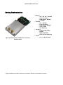
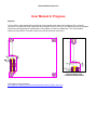
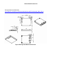
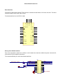
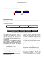
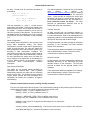
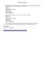
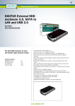
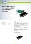
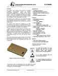
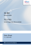
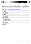
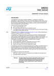
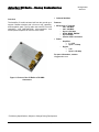
AstroDev CII Radio – Boeing Customization PRODUCT OVERVIEW 04 August 2010 Version 0.1 • Cubesat Satellites Overview The AstroDev CII radio has been built from the ground up to support CubeSat missions with a focus on cost, capability, and integration goals. The CII radio uses new RF front end technology, new MSP430F54XX microcontrollers, and efficient power amplifiers to meet the users needs. Features: • RF Receive or Transmit: o 440 – 460 MHz o 900 – 928 MHz o Up to 115.2 kbps o GFSK, BPSK, OQPSK o Up to 36 dBm o Choice of RF Connectors • Power: o Amplifier: 5 – 8.5V Up to 1.75 Amp o Digital: 3.3V Up to 0.150 Amp For more information, contact: [email protected] Figure 1--Picture of the CII Radio w/ RA SMA Connectors. * Preliminary Specifications, Subject to Change During Development © Astronautical Development, LLC 2008 Helium Radio Product Line Boeing Customization • Receive: o 440 – 450, 455 – 462 MHz o Up to 115.2 kbps o GFSK, BPSK*, OQPSK* o < 0.5 Watt • Transmit: o 900 – 928 MHz o Up to 115.2 kbps o GFSK, BPSK*, OQPSK* o Up to 33 dBm o 30% Efficiency • Interface: o Samtec FTSH Header o RS-422 o Right Angle SMA o #2-56 Thermal Strapping • Power: o 9 to 13 V @ 0.67 Amps Figure 2--Picture of the CII Radio Rev A on Carrier Interface Board. * Higher modulations funded to implement in hardware. Software customization not funded. Helium Radio Product Line User Manual In Progress Physical: The CII radio is a plug module that mounts flush onto a printed circuit board using a Samtec CLP-112 series connector. The radio case is 6061 aluminum with a footprint of 40 mm x 50 mm. The radio has two #2-56 threaded holes for thermal straps and is machined flat on all surfaces to conduct or radiate heat. The recommended footprint is shown below. The radio mounts using 4 #2-56 screws at each corner. Figure 3 Zoom In Pad Location and Dimensions COTS Altium Library Footprint: www.astrodev.com/public_html2/downloads/solidmodels/CII_Radio_Altium.zip Helium Radio Product Line Boeing Solidworks Solid Model: www.astrodev.com/public_html2/downloads/solidmodels/FinalAssembly_SMA_RA.zip Figure 4 Boeing Radio Module Dimensions Helium Radio Product Line Board Interface: The COTS CII radio uses a Samtec FTS to connect to a board mounted Samtec CLP series connector. The board interface includes JTAG, Power, and I/O lines. 1 3 5 7 9 11 13 15 17 19 0 Case/GND 0 Case/GND 0 Case/GND Case/GND 0 The header definition for the COTS CII radio: WatchDog In/Out UART_RX RST UART_TX GND 7.0-9.0V GND 7.0-9.0V 3.3V 3.3V JTAG_TST JTAG_RST N/C JTAG_TCK JTAG_3.3V JTAG_TDI JTAG_TMS JTAG_TDO JTAG_GND N/C 2 4 6 8 10 12 14 16 18 20 Boeing Carrier Board Interface: Due to the customization needs for the CII Bus, a carrier board was created to condition the power, format the I/O, and meet the CII Bus standard connections. The customized Boeing CII carrier board header definition: P4 WATCH_DOG_OUT/IN R01 0.0 Ohm R00 Reset 0.0 Ohm FSRI 422_A_to_radio 422_Y_from_radio 1 3 5 7 9 11 13 15 17 19 2 4 6 8 10 12 14 16 18 20 Header 10X2 FSRO 422_B_to_radio 422_Z_from_radio BUS_VOLTAGE Helium Radio Product Line The Boeing CII carrier JTAG board header definition: Prog M1_TEST +3.3VD 1 3 5 7 9 M1_TMS M1_RST/NMI M1_TCK M1_TDI M1_TDO 2 4 6 8 10 Header 5X2 Boeing Software Interface: The CII radio is accessed over a standard RS-422 level UART. The UART protocol uses heritage software for all radio interaction. Command and Data Interface Header (8 Bytes) Payload (0 to 255 Bytes) Payload Check Sum A (1 Byte) Payload Check Sum B (1 Byte) Figure 5--Packet structure for the Command and Data Interface (CDI). Sync Characters (2 Bytes) Command Type (2 Byte) Payload Size (2 Bytes) Header Check Sum A (1 Byte) Header Check Sum B (1 Byte) Figure 6--Description of the packet header used in the CDI. Users interface to the Helium radios through the Command and Data Interface (CDI). Through the CDI, users configure the radio, send data to be transmitted, and recieve data that was received. Users access the CDI through the UART port using RS-422 standard. The packet format for the digital interfaces is pictured above in Figure 5. It consists of an 8 byte, fixed length header, a variable payload segment from 0 to 255 bytes, and 2 check sum bytes. The header is described in Figure 6. The sync characters of the header are a two byte sequence1: Sync Character 0: 0x48 or ‘C’ Sync Character 1: 0x65 or ‘2’ The next two bytes in a message header are the command type. Commands can be divided into two types representing the direction of the communications. Data entering the radio is noted as 1 Bit stuffing is not needed because checksums and packet lengths are used. I-messages. I-messages are command types that begin with 0x10. Data leaving the radio is noted as O-messages. O-messages are messages that begin with 0x20. The full command list is given later in this documentation in section Transceiver serial communications interface description. The “Payload Size” field of the header is a two byte, unsigned short integer containing the total number of bytes in the packet payload. The most significant byte (MSB) is given first. The maximum payload size is 255. Two checksum bytes are appended to the header for error detection. The 8-bit Fletcher algorithm (see RFC 1145 which describes TCP) is used to calculate the checksums. The algorithm works as follows: A buffer, Buffer[N], contains data over which the checksum is to be calculated. The two checksum values (CK_A and CK_B) are 8-bit unsigned integers only. Note, if you implement it with larger sized integers, be sure to mask both CK_A and CK_B with 0xFF after the calculations complete to ensure they Helium Radio Product Line are 8-bit. Psuedo-code for checksum calculation is given below. CK_A = 0, CK_B = 0 For(I=0;I<N;I++) { CK_A = CK_A + Buffer[I] CK_B = CK_B + CK_A } This loop calculates CK_A and CK_B which are then appended to the header. Following the header is the packet payload, which has a length as specified in the header. A payload checksum is then used to verify the accuracy of the payload. The checksum is calculated across all pertinent bytes of the message excluding the two sync characters of each message ‘C2’. Radio Configuration The default radio configuration is set at factory load during radio acceptance testing. This default configuration is stored in flash and is applied during power up and soft reset. The user can change the radio configuration after radio processor power up by providing a valid configuration command. The configuration message can change multiple settings at once. Changes take effect immediately, however the user should allow a settling time of at least 250 ms for settings to be applied due to the settling time of PLLs. Default settings are described in section Transceiver serial communications interface description. Data Protocol Description The radios do not process packet payloads for transmitted and received data. Data is passed transparently between the radio and the controlling device over the CDI. This enables the user to define custom packet formats that may incorporate such capabilities as forward error correction, encryption, and whitening. The radios implement a subset of the AX.25 packet radio protocol as defined by http://www.tapr.org/pub_ax25.html. Only the handling of UI frames is implemented, not full connected mode. Users are able to configure the source and destination call signs, the packet length, and the TX tail and head parameters (see the command list in Error! Reference source not found.). The radio performs all packetization functions such as bit stuffing and check sum calculations. Transmit Overview All data received from the hardware interface is immediately transmitted unless the radio is busy with a current transmission. Data to be transmitted will be temporarily retained in the transmission buffer based upon the RF baud rate and the buffer length. During transmission, the radio operates as described previously in the Command and Data Interface section of this document. These parameters default to standard AX.25 settings and are defined later in section Transceiver serial communications interface description. Receive Overview During reception, the radio maintains the interface as described previously in the Command and Data Interface section of this document.. The raw data received is placed into the payload section of the message. These parameters default to standard AX.25 settings and are defined later in section Transceiver serial communications interface description. Example communications session, sending a No-Op command: First, the user implements a No-Op request. This is performed by loading an array with the proper values and sending them to the radio over a serial connection, below in pseudo code. buffer[0] = SYNC_1; //This is a #define value of ‘C’ buffer[1] = SYNC_2; //This is a #define value of ‘2’ buffer[2] = I_MESSAGE_TYPE; //This is a #define value of 0x10 buffer[3] = NO_OP_COMMAND; //This is a #define value of 0x01 buffer[4] = 0x00; //There is no payload size information in a No-Op request buffer[5] = 0x00; calculate_header_checksum(&buffer[2]); //The first two synch bytes are not included in the checksum serial.Write( &buffer[0], 8 ); //send the information out your serial port Helium Radio Product Line The radio then responds to the request with either an acknowledge or not-acknowledge. An acknowledge is a response with the value 0x0A0A in the payload bytes. For example: Byte[0] = 'C'; Byte [1] = '2'; Byte [2] = 0x20; Byte [3] = NO_OP_COMMAND; Byte [4] = 0x0A; Byte [5] = 0x0A; Byte [6] = Checksum A; Byte [7] = Checksum B; A not-acknowledge is a response with 0xFFFF in the payload bytes. For example: Byte[0] = 'C'; Byte [1] = '2'; Byte [2] = 0x20; Byte [3] = NO_OP_COMMAND; Byte [4] = 0xFF; Byte [5] = 0xFF; Byte [6] = Checksum A; Byte [7] = Checksum B; This is how most communications are performed with the radio. When messages include a payload, the response or command must contain a payload length value and the payload with the message. Driver Code: Example driver code is available: www.astrodev.com/public_html2/downloads/programs/example_code.cpp