Transcript
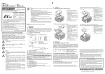
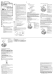
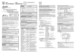
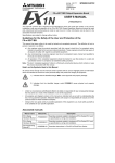
Side Side A Side B ENGLISH JAPANESE Caution • The module case is made of resin; do not drop it or subject it to strong shock. Doing so may damage the module. • When disposing of this product, treat it as industrial waste. • When the FX1N-BAT is transported attached to a PLC and the life cycle has passed or the BATT.V LED turns ON when the PLC is powered, the data backed up by the capacitor will have become random. Check the following two points before transporting the installed FX1N-BAT attached to the FX1N series PLC. - Life cycle of FX1N-BAT (life cycle: 2 year at 25 °C) - "BATT.V" LED of FX1N-BAT is OFF when the FX1N series PLC is powered up. • During transportation avoid any impact as the PLC is a precision instrument. It is necessary to check the operation of PLC after transportation, in case of any impact damage. • During transportation avoid any impact to the battery (FX1N-BAT) as the PLC may be seriously damaged by liquid leakage etc. from the battery. FX1N-BAT BATTERY UNIT USER'S MANUAL JY997D10201 A Date July 2003 • This manual contains text, diagrams and explanations which guide the reader in the correct installation and operation of the FX1N-BAT battery unit. It should be read and understood before attempting to use the unit. • Further information for the FX1N series PLC can be found in the FX1N Series Hardware Manual. • If in doubt at any stage of the installation of FX1N-BAT, consult a professional electrical technician who is qualified and trained to the local and national standards which apply to the installation site. • If in doubt about the operation or use of the FX1N-BAT please consult the nearest Mitsubishi Electric distributor. • This manual is subject to change without notice. • The company name and the product name described in this manual are the registered trademarks or trademarks of each company. 2003 Mitsubishi Electric Corporation Guideline for the safety of the user and protection of the FX1N-BAT. This manual provides usage information for the FX1N-BAT Battery Unit. The manual has been written to be used by trained and competent personnel. Note's on the symbols used in this manual At various times throughout out this manual certain symbols will be used to highlight points of information which are intended to ensure the users personal safety and protect the integrity of equipment. Whenever any of the following symbols are encountered, its associated note must be read and understood. Each of the symbols used will now be listed with a brief description of its meaning. Hardware Warnings When installed on the FX1N PLC, the FX1N-BAT Battery Unit (hereinafter referred to as FX1N-BAT) is used to ensure that the capacitor-backed devices do not become random. When using the FX1N-BAT, the status of the capacitor-backed devices will be maintained as long as the battery in the FX1N-BAT has not expired. (life cycle: 2 year at 25 °C). 1) Turn Off the power to the PLC. 2) Remove the top cover of the PLC. 3) Attach the top cover (A) of the FX1N-BAT accessory. 4) Secure the top cover (A) to the PLC with a screw (B). The screw should be tightened with a torque of 0.3 to 0.6 N • m. The screw must be secured to prevent malfunction due to a loose connection. 5) Fix the FX1N-BAT to connector (C) on the PLC. 6) Turn On the power to the PLC. (B) (A) 40 (1.58") For installation of the expansion board, refer to the FX1N Hardware Manual. 1) Turn Off the power to the PLC. 2) Remove the top cover of the expansion board. 3) Remove section (A) with wirecutters to expose the connector. 4) Attach the top cover of the expansion board. 5) Secure the top cover to the PLC with screw (B). The screw should be tightened with a torque of 0.3 to 0.6 N • m. The screw must be secured to prevent malfunction due to a loose connection. 6) Fix the FX1N-BAT to connector (C) on the expansion board. 7) Turn On the power to the PLC. (C) (A) 3) (B) 1) 1.1.2 4) 2) 1) BATT.V LED 2) Hook for fixation 3) Connector for PLC 4) Product name and Lot number Lot Number LOT.37 Production month: 1-9 = Jan. - Sept., X = Oct., Y = Nov., Z = Dec. Production year: e.g. 3 = 2003, 5 = 2005 When the "BATT.V" LED of the FX1N-BAT lights, do not leave the PLC unpowered for 10 days or more until the FX1N-BAT is exchanged to the new one. For the operation after detecting low voltage, refer to section 4.2. Life cycle of FX1N-BAT: 2 years at 25 °C (Guarantee: 1 year) Caution • Cut off all phases from the power source before installation or maintenance work to avoid electric shock. Incorrect operation can lead to serious damage to the product. • Use the screwdriver in the correct position, when removing the FX1N-BAT. If the screwdriver slips, it is likely to result in injury. • Securely install the FX1N-BAT in the fixed connector. When installed incorrectly, PLC will malfunction due to faulty contacts. Exchange Procedure - When not used with an expansion board 1) Supply power to the PLC for 30 minutes or more. 2) Turn Off the power to the PLC. 3) Put screwdriver at the right side of FX 1N-BAT as shown in the figure on the left. 4) Go a little up FX1N-BAT by operating the screwdriver as shown in the figure on the left. 5) Remove the FX1N-BAT holding it as shown in the figure on the left. 6) Install the new FX1N-BAT onto the PLC. 7) Turn On the power to the PLC. 3.2 When used with an expansion board 1.1.1 Dimensions and Each Part Name Unit: mm (inches) Accessory: Top cover for FX1N-BAT × 1, M3 screw to fix top cover × 1 3) Indicates a point of further interest or further explanation. Exchange Procedure - When used with an expansion board 1) Supply power to the PLC for 30 minutes or more. 2) Turn Off the power to the PLC. 3) Remove the FX1N-BAT holding it while pressing (A) as shown in the figure on the left. 4) Install the new FX1N-BAT onto the PLC. 5) Turn On the power to the PLC. 4. Maintenance 4.1 Detecting Low voltage in the FX1N-BAT 1.2 System Configuration Caution • Units should not be installed in areas subject to the following conditions: excessive or conductive dust, corrosive or flammable gas, moisture or rain, excessive hear t, regular impact shocks or excessive vibration. • Cut off all phases from the power source before installation or maintenance work to avoid electric shock. Incorrect operation can lead to serious damage to the product. • Use the screwdriver in the correct position when removing the FX1NBAT. If the screwdriver slips, it is likely to result in injury. • To avoid electric shock, replace the top cover, after installation or wiring work is completed, and before supplying power and operating the unit. • Securely install the FX1N-BAT in the fixed connector. When installed incorrectly, the PLC will malfunction due to faulty contacts. • Do not disassemble or modify the module. Doing so may result in failure, malfunction, injury, or fire. 3.1 When not used with an expansion board (C) 3) Danger • Perform cleaning of the module only after turning OFF all external power supplies. Failure to do so may cause failure or malfunction of the modules. 4.3 Exchange Procedure Caution • Cut off all phases of the power source before installation or maintenance work to avoid electric shock. Incorrect operation can lead to serious damage to the product. • Securely install the FX1N-BAT in the fixed connector. When installed incorrectly, the PLC will malfunction due to faulty contacts. 1.1 Introduction 1) Indicates that the identified danger WILL cause physical and property damage. 2) Indicates that the identified danger could POSSIBLY cause physical and property damage. 3. Installation 1. Introduction 32(1.26") Revision 11.3 Manual Number (0.45") A One FX1N-BAT can be installed in one FX1N series main unit. The FX1N-BAT can be used with an expansion board. See the following table for possible configurations. Expansion Board / Display Module / Memory Cassette Using with FX1N-232-BD, FX1N-422-BD,FX1N-485-BD, FX1N-CNV-BD, FX1N-8AV-BD, FX1N-4EX-BD, FX 1N-2EYT-BD Not using with FX1N-2DA-BD, FX1N-1DA-BD, FX1N-5DM, FX1N-EEPROM-8L 2. Specifications The "BATT.V" LED of the FX1N-BAT lights when the low voltage is detected on powerup of the FX1N series PLC. It is possible to output the status of the "BATT.V" LED to an output terminal on the PLC with the following programs. Move K!!! into D8159 to enable M(!!!+4) to turn ON when the FX1N-BAT voltage becomes low. Note that M!!!-M(!!!+15) are also occupied for the low voltage detection. Therefore, these devices should not be used for other applications. M8002 MOV K0 D8159 Moving K0 into D8159 will occupy the flags, M0 to M15, for detecting low voltage in the FX1N-BAT. Y0 When the FX1N-BAT experiences low voltage, M4 is turned ON. M4 (A) 4.2 Operation After Detecting Low Voltage in the FX1N-BAT 2.1 General Specifications The general specifications are equivalent to those of the FX1N main unit. 2.2 Subject of Backed-up The devices in the table below are backed up by the FX1N-BAT. Device Description Capacitor-backed device M512 ~ M1535, S128 ~ S999, T246 ~ T255, C32 ~ C234, D256 ~ D7999 Current time The "BATT.V" LED of FX1N-BAT lights when low voltage is detected on power-up of the FX1N series PLC. Ten days after the "BATT.V" LED lights, the capacitor inside the PLC will begin to back up the devices with whatever charge was present at the last power down of the PLC. It is necessary to power-up the PLC every ten days, for a period of 30 minutes, to recharge the capacitor after the FX1N-BAT is no longer backing up the devices. If power is not supplied for ten days or more, the capacitor-backed data will become random. Further information concerning the capacitor backup can be found in FX1N Hardware Manual. HEAD OFFICE : MITSUBISHI DENKI BLDG MARUNOUTI TOKYO 100-8310 HIMEJI WORKS : 840, CHIYODA CHO, HIMEJI, JAPAN