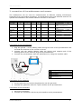
1
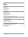
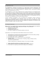
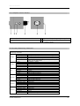
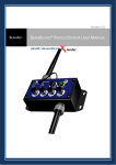
HKS Prozesstechnik WeldScanner Anschließen der Hardware: ® Um den CAN-Bus Dongle betreiben zu können, brauchen Sie an Ihrem Computer - eine parallele Schnittstelle (25 poliger Sockel) sowie - einen PS/2 Anschluss (zur Stromversorgung). manual Bitte schließen Sie den Dongle entsprechend an und starten den Computer. HKS-Prozesstechnik GmbH Heinrich Damerow Str. 2 D-06120 Halle Tel.: ++49 345 68309-0 E-Mail: [email protected] www.hks-prozesstechnik.de manual WeldScanner 1 HKS Prozesstechnik content: 1. INTRODUCTION 3 1.1 WELCOME 1.2 SAFETY INSTRUCTIONS 1.3 THERMS OF THE LICENCE 1.4 APPLICATION AREA 1.5 SCOPE OF DELIVERY 3 3 3 4 4 2. SPECIFICATIONS 5 2.1 WELDSCANNER 2.2 PROCESSSENSOR P1000 2.3 COMPACT-SENSOR K1000 2.5 SURWAY MEASURING CHANNELS 2.5 SURWAY WELDSCANNER DEVICE 2.6 ANALOG INPUTS 5 5 6 6 7 8 3. CONNECTION OF THE WELDSCANNER AND SENSORS 9 4. USING THE WELDSCANNER 11 4.1 SWITCH ON OF THE SYSTEM 4.2 RECORDING OF WELDING SEAMS 4.3 FUNCTIONS OF THE MAIN MONITOR 4.4 ANALYSING AND PRINT OUT OF THE RECORDS 11 11 12 14 5. PC SOFTWARE FOR ANALYSING THE WELDING DATA 16 5.1 READ IN THE RECORDS FROM USB MOMORY STICK 5.2 COSTUMISING THE PROGRAM 5.3 ANALYSING THE WELDING DATA 5.4 DATA MANAGMENT 16 17 18 19 manual WeldScanner 2 HKS Prozesstechnik 1. Introduction 1.1 Welcome Congratulations on your new WeldScanner. Please read through this user manual carefully and in full before use. The WeldScanner is a device operated with supply voltage. Only if the device is operated correctly and the safety instructions are complied with can we guarantee that the user will not be harmed in any way. In addition, if you take note of the instructions on the following pages about how to use the device properly, this will ensure the life span of the WeldLogger® and protect you, the user, from time-consuming and costly repairs. And so from this point of view it is definitely worth taking 15 minutes to read this instruction manual. We wish you lots of enjoyment with this unique product. 1.2 Safety Instructions The WeldScanner® should not be operated or stored in excessively hot, cold or damp surroundings. The device contains metals and electronic components. Once the device, the internal buffer accumulator or the clock battery have reached the end of their life span, please dispose of these components in accordance with the statutory regulations in your country. The WeldScanner complies with the valid German and European directives and regulations governing measuring devices. Should you have any doubts about the installation, operation or safety of the product supplied, please contact the manufacturer. If it should be necessary to open the basic device, all the cables must be disconnected. As the WeldScanner is used in connection with welding power sources and welding processes, the existing precautionary and safety measures in this area must be observed. Only use the original attachments (serial junction cable, welding connection cable, etc.). Using different attachments is dangerous and can result in the destruction of the basic WeldScanner device or the PCs being used. The WeldScanner should not be operated or stored in excessively hot, cold or damp surroundings. The device contains metals and electronic components. Once the device, the internal buffer accumulator or the clock battery have reached the end of their life span, please dispose of these components in accordance with the statutory regulations in your country. 1.3 Therms of the Licence The software and the enclosed literature is subject to copyright. The licence issued covers only specific and appropriate use. The manufacturer accepts no liability for the faultlessness of the software. In particular, he makes no guarantee that the software is sufficient for the requirements and purposes of the licensee or will work together with other programs selected by the licensee. Responsibility for the correct choice and the consequences of using the software, as well as the results intended with it, lies with the licensee. manual WeldScanner 3 HKS Prozesstechnik 1.4 Application Area The WeldScanner combines the functions of a "data logger","digital oscilloscope" and “ cal i br at i on”into one mobile, industrial-strength hand-held device. It is designed as a multi-purpose aid for the welding specialist for analysing faults, documenting welding data and calibrating power sources. The WeldScanner can be easily attached by the enclosed sensors to the welding power source. After the start of a welding process is automatically registered, the display shows the parameters for welding voltage, welding current, wire speed and gas flow and stores the wave forms automatically. A freely configurable measuring channel is also available. Once a welding process is finished, the mean average values of the parameters and the wave forms are displayed and can be also printed directly. Further evaluation possibilities, such as analysing the parameter courses, archiving, printing out documentation and calibration logs, are carried out with the easily comprehensible Windows software. The data can be copied from the WeldScanner via a USB memory stick to the PC. Here they are available for evaluation in an easy-to-view manner according to date, time and number. 1.5 Scope of Delivery Please check the complete delivery with your delivery note, before putting into operation of the device. The following basic components are part of every delivery: A. WeldScanner basic device B. Standard mains cable C. 128-MB USB memory stick D. CD with PC software for the data evaluation at the PC Depending on your measurement task different sensors were enclosed: E. F. G. H. I. J. Process Sensor P 1000 for the measuring of welding current and welding voltage two welding current cable for the process sensor connecting cabel sensor - WeldScanner wire feed sensor for the measurement of wire feed speed gas flow sensor compact sensor for the measurement of welding voltage, welding current, wire feed and gas flow rate Further components can optionally be part of the extent of supply: K. printer with USB interface for printing out the results L. USB keyboard to the extended operator petition when calibrating M. load resistor for adjusting current and voltage when calibrating manual WeldScanner 4 HKS Prozesstechnik 2. Specifications 2.1 WeldScanner 1 2 3 4 - type plate main connection 2-x USB interface display 5 6 7 8 - handle jack for sensors jack for reserve channel operating wheel 2.2 Processsensor P1000 1 - jack welding voltage positive pole 2 - jack for sensor cabel 3 - jack for gas flow sensor manual WeldScanner 4 - jack welding voltage negative pole 5 - jack for wire feed sensor 7 - hole for welding current cabel 5 HKS Prozesstechnik 2.3 Compact-sensor K1000 1 - Interface Binzel to the wire feed device 2 - jack for sensor cabel 3 - jack welding voltage negative pol 4 - Interface binzel to the cabel of the welding torch 2.5 Surway Measuring Channels Measuring Channels voltage current wire Gas flow Reserve 1 Reserve 2 range measuring value accuracy frequency remark range measuring accuracy frequency remark range Verfahren accuracy frequency remark range measuring accuracy frequency remark range measuring accuracy frequency remark range measuring accuracy frequency remark manual WeldScanner value value value value -100V bis +100V average value (Scopemode without smoothing) < 1% DC to 45kHz 100Hz (scopemode 6.4 kHz) HF-ignat. Voltage only by using HKS original voltage cable, valid for HKS P1000 -1000A bis +1000A average value (Scopemode without smoothing) < 1% DC to 45kHz 100Hz (Scopemode 6.4 kHz) 1000A for max. 1min, valid for HKS P1000 0-25m/min, Ø < 2,5mm frequency < 2,5% 100Hz Valid for HKS wiresensor 0-25l/min (Argon) Mass flow meter < 5% 100 Hz Valid for HKS gassensor customised customised customised 100 Hz analog input, no galcanic isolation customised customised customised 100 Hz analog input, no galcanic isolation 6 HKS Prozesstechnik lfd.Nr. 1 2 amount analog input Counter input 5 2 Max. values galvanic isolation +/- 0...10V AC/DC rectangular pulses with max frequency 20kHz, amplitude +10...30V, max.30mA no Opto coupled remarks: 1.) By using measuring transducers from other manufacturers should be noted the galvaic isolation of measuring signal and supply voltages 2.) The counter inputs work with push/pull outputs of the resolver. By using open collector outputs should be used pull up resistors. 3.) By using TTL-output resolver should be used level converters. 4.) By using input frequencies over 20 kHz should be used frequency dividers. 2.5 surway WeldScanner device Eigenschaften device environment Welding tec. Display interface Data storage weight dimensions (LxBxH) electromagnetic compatibility accreditation cooling system supply Input current power input Intern flash memory Intern RAM operating temperature Temperature at stock Rel. humidity MIG, MAG, TIG, MANUAL, SMW Typ Typ USB-memory stick manual WeldScanner < 4,5kg 240x160x160mm EN55022-B,CISPR22-B, FCC-Part 15ClassB, EN50082-1 VDE, UL, c-UL convection 90V -132 V / 180V- 264VAC, 47-63 Hz at 90V AC input max. 1,1 A Max. 30 W 256 Mbyte 256 Mbyte 0 bis 40°C -20 bis +80°C 0% bis 90% at 0 bis 30°C See ranges Col orLCD 6, 5“ 2 x USB 1 128 MB 7 HKS Prozesstechnik 2.6 analog inputs analog input SENS Pin-Nr. 1 2 3 4 5 6 7 8 9 10 11 12 -SENS- Standard signal Umin./V Umax./V intern Welding current + Welding current Welding voltage+ Welding voltage nc supply –12V DC Wire speed + Wire speed supply +12V DC supply GND Gas flow Gas flow + 0 0 0 0 +10 0 +10 0 AIN0+ AIN0AIN1+ AIN1- -12,5 10/100Hz 0 +11,5 0 0 0 -11,5 30/20kHz 0 +12,5 0 0 +10 U12NAI INCR1+ INCR1U12PAI AGND AIN4AIN4+ *remark: The input of the wire speed is not suitable for voltage inputs, only for rectangular pulses The used resolvers should have push pull outputs. interface SENS Analog input SENS Pin-Nr. 1 2 3 4 5 6 7 8 Typ/Standard M23 -RESERVE- Pole 12 Standard signal Umin./V Umax./V supply +12V DC supply GND Gas flow + Gas flow temperature + temperature Speed + Speed - + 11,5 0 0 0 0 0 10/100Hz 0 + 12,5 0 +10 0 +10 0 30/5kHz 0 intern U12PAI AGND AIN6+ AIN6AIN2+ AIN2INCR2+ INCR2- *remark: The input of the speed is not suitable for voltage inputs, only for rectangular pulses The used resolvers should have push pull outputs. interface Typ Pole SPEED M18 8 manual WeldScanner 8 HKS Prozesstechnik 3. connection of the weldscanner and sensors The weldscanner can be used for measurements at different welding technologies. Depending from the welding technology, the weldscanner work with different sensors. For optimal documentation the suitable sensors are listed in the table: technology CH1 Strom x CH 2 Spannung x TIG x x TIG-cold wire Plasma x x x x x pilotgas Plasma cold wire E-Hand SMW x x x pilotgas x x x x MIG-MAG CH 3 Draht x CH 4 Gas x CH 5 spezifisch CH 6 spezifisch Prozesssensor + wire + gas oder Kompaktsensor Prozesssensor + wire + gas Prozesssensor + Draht + Gassensor Prozesssensor + gassensor1 + gassensor2 Prozesssensor + wire + gassensor1 + gassensor2 Prozesssensor Prozesssensor SMW + wire SMW x x sensors x x Connection of the processsensor 1. Plug the ground – or the welding cable through the hole of the processsensor and see that the direction of the current is correct. 2. Connect with the welding adaptor cable the positive and negative pole of the welding power source with the plug at the processsensor. 3. Connect the processsensor with the weldscanner by using the interface cable. 1 2 3 4 5 Welding voltage adaptor (F) Welding voltage adaptor (F) Processsensor (E) Groundkabel Interface cabel WeldScannerProcesssensor (G) Connection of the gassensor 1. Cut the gas main and mount the gassensor into the gas main. 2. Connect the gassensor with the 3 pole interface at the processsensor. Connection of the wiresensor 1. Mount the wiresensor. 2. Connect the wiresensor with the 4 pole interface at the processsensor manual WeldScanner 9 HKS Prozesstechnik Connection of the compaktsensor 1. Mount the compactsensor at the wire feeder with BIZEL EURO Connector between wire feeder and torch. 2. Connect with the welding adaptor cable negative pole of the welding power source with the plug at the compactsensor. 3. Connect the compactsensor with the weldscanner by using the interface cable. 1 2 3 manual WeldScanner Welding voltage adaptor (F) Interface cabel WeldScannercompaktsensor (G) compaktsensor (J) 10 HKS Prozesstechnik 4. using the WeldScanner 4.1 switch on of the system he WeldScanner has a wide range tension input with automatic range recognition. The equipment can be attached to all common lines (110 V or 230 V). Connect the weldscanner (A) with standard mains cable (B) and switch on the weldscanner. After app. 1 min. the weldscanner is ready to use. The monitor shows the main window. The weldscanner can be operated by turning and pushing the wheel at the right hand side. By turning the wheel you jump between the possible functions. The activated function has red colour. By pushing the wheel the activated function is chosen. 4.2 recording of welding seams If the weldscanner device shows the main monitor you can start the measurment and recording the welding data. Start the welding process, weldscanner will automatically recognise the welding start and begin to record the welding. The actual values of the welding parameters and the duration of the welding will be indicate at the screen. After welding the weld will be storage automatically. For identification of the start and the end of the welding the weldscanner has a intern trigger: pretrigger: pasttrigger: triggervalue on: triggervalue off: 0,5 s 1,0 s 15 A 10 A That means: The recording starts 0.5 sec. before the welding current is more than 15 A and ends 1.0 sec. after the welding current is less than 10 A. manual WeldScanner 11 HKS Prozesstechnik 4.3 functions of the main monitor 1 2 3 10 4 11 5 12 13 6 7 14 15 8 16 9 17 1 2 3 4 5 6 7 8 9 10 11 12 13 14 15 16 17 Fill level of the ring memory Change of charge number Table of all welding seams Save welding data to memory stick Delete welding data from ring memory Scope mode (OPTION) Calibration mode (OPTION) Configuration monitor softwareupdate Recording number Charge number Welding current meter Welding voltage meter Wire speed meter Gas flow meter Reserve channel 1 Reserve channel 2 manual WeldScanner 12 HKS Prozesstechnik Ring memory (1) The fill lever of the ring memory will be shown in %. The accurate amount of the ring memory depends from amount and duration of the seams. There exist the following limitations: Amount of weldings: max. 2000 Duration of all welding: app. 13 hours at 4 measuring channels (current, voltage, wire speed and gas flow). If the ring memory is filled and no data will be stored to the USB memory stick, the first records will be automatically deleted in order to have space fort he new welding record. Change of the charge number (2) The charge number will be stored with each record. To change this charge number turn the wheel to the push button Charge+/- is active (red) and push the wheel. The push button Charge+/- change their colour into blue and the charge number (11) is active (red). You can change now the charge number by turning the wheel. To acknowledge the new charge number, push the wheel and the new charge number is valid for the following records. Delete of the ring memory (5) If you don´t need the records at the ring memory (t.e. you have stored them to USB memory stick), you can delete the records from ring memory. To delete the records from ring memory turn the wheel to the push button Delete Data is active (red) and push the wheel. Confirm the security question Are you sure with Yes, to delete the records or with No, to let the datas into the ring memory. After successful deleting the weldscanner automatically goes back to the main windows. Store records to the USB memory stick (4) For storage the datas from ring storage use the delivered USB memory stick. For memory sticks of other producers we can not guarantee the correct function. Insert the memory stick into one of the USB interface at the weldscanner. To save the records from ring memory turn the wheel to the push button Save Data is active (red) and push the wheel. The weldscanner check if the USB memory stick is empty and starts the storing procedure. If the USB memory stick is not empty, all datas at the memory stick are deleted. After successful saving the data to the USB memory stick the weldscanner asks, if the records from ring memory should be deleted. Press Yes to delete the data from ring memory or no to go back without deleting the data from ring memory. The welding data at the USB memory stick can be evaluated with the delivered PCsoftware. => see chapter 5 Update of the WeldScanner-software (9) If there is a new weldscanner software aviable, you get from your distributor a delailed information to update the weldscanner. To update the weldscanner software in the weldscanner device turn the wheel to the push button update is active (red) and push the wheel. NEVER SWITCH OFF THE WELDSCANNER DEVICE DURING UPDATE !!! manual WeldScanner 13 HKS Prozesstechnik 4.4 analysing and print out of the records To analyse the records from ring memory turn the wheel to the push button Result is active (red) and push the wheel. The monitor change to a table, listed all records from ring memory. Each row is one welding seam. In this table are listed the mean values of all parameters, the duration, the charge number, the date and the time of the welding. 1 2 3 4 Print out the list of all welding seams (2) Connect the from HKS recommended printer to the USB interface of the weldscanner. Remark, that not each printer work properly with the weldscanner. A actual list of aviable printers you can find at the WEB (www.weldscanner.de) or ask our service hotline. To print out a complete list of all records from ring memory turn the wheel to the push button Print is active (red) and push the wheel. A complete list will be printed. Depending from the amount of weldings, this could be many pages. Detailed view of a record (1) To analyse a several welding from the list of all records from ring memory turn the wheel to the push button Select is active (red) and push the wheel. The push button Select change their colour into blue and first record is active (red). You can change now the active record for analysing by turning the wheel. To see a detailed view of the activated record, press the wheel for longer time. A new window with the curves and the averaged values of the welding parameter will be shown. In the curve chart the times for pre- and pasttrigger are marked with green and blue line. manual WeldScanner 14 HKS Prozesstechnik To analyse a several welding from the list of all records from ring memory turn the wheel to the push button Select is active (red) and push the wheel. With the buttom Channel select can be chosen, which curves in the chart will be shown. To switch on/off a curve from the chart turn the wheel to the push button Channel select is active (red) and push the wheel. The push button Channel Select change their colour into blue and first parameter to switch on/off is active (red). You can change now the active parameter to switch on/off by turning the wheel. To switch on/off the selected parameter, press the wheel for longer time. By pressing the wheel for a short time you go back and can choose now between the functions Channel Select –Print –Back by turning the wheel. To print out the detailed view with curve chart, connect the from HKS recommended printer to the USB interface of the weldscanner. Remark, that not each printer work properly with the weldscanner. A actual list of avialable printers you can find at the WEB (www.weldscanner.de) or ask our service hotline. To print out a complete list of all records from ring memory turn the wheel to the push button Print is active (red) and push the wheel. A page with detailed view will be printed. To quit the detailed view turn the wheel to the push button Back is active (red) and push the wheel. By pressing the wheel for a short time you go back and can choose now between the functions Select –Print –Back by turning the wheel. To quit the table view and show the main monitor turn the wheel to the push button Back is active (red) and push the wheel, Switch of the weldscanner The weldscanner can be switched off at any position with the main switch. NEVER SWITCH OFF THE WELDSCANNER DEVICE DURING UPDATE !!! manual WeldScanner 15 HKS Prozesstechnik 5. PC Software for analysing the welding data With the PC software WeldScanner welding data, recorded with the weldscanner device can be read in analysed into a office PC. The analysing functions with the PC software are more extensive than at the weldscanner device. The Software works with operating systems Windows 98, Windows 2000 or Windows XP. For installation of the PC software Weldscanner follow the instructions during installation. 5.1 Read in the records from USB momory stick Start the program weldscanner evaluation from desktop or from windows lunch buttom.. Remark: If you want read in records from USB memory stick you had to connect the USB memory stick at your computer before starting the software weldscanner at the PC. At the first start of the software you will see a empty table. At the right side of the windows you will see a menu bar with function buttons. If you never had read data from weldscanner, you should read in some records from USB memory stick. For that you need a USB memory stick with welding data recorded with your weldscanner device. Be sure that the USB memory stick has been connected before starting the weldsanner software, that press the button Load. Choose at the opened window the option weldscanner at the right hand side of the window and choose than the drive with the USB memory stick from the lsit at the left hand side. At the USB drive you will see the directory ws_scan. Open this directory by doubleclick and mark the file weldscanner.wsd. Start the read in function by pressing the OK-Button. After successful read in of the records, all welding data from USB memory stick will be listed in the table. The welding are sorted in descending order, so that the last welding is situated as first row. If you read in more welding data later, this records will be added to the table. manual WeldScanner 16 HKS Prozesstechnik 5.2 costumising the program The table can be individually djusted, that means, you can choose the order of the columns in the table and also which columns you want to see. The button Configuration starts the configuration monitor of the table. The table can be individually adapted, i.e. the columns can be selected that are to be displayed, and the sequence of the columns can also be determined. The button Configuration opens the configuration screen. In the window Actual fields the current columns in the table are listed. With the keys Right / Left columns can be removed or added; the keys Up / Down determine the position of the column selected. The recordings can be sorted in ascending or descending order according to a number of columns that are to be included in the sort function. Remark: the carge number you have defined at the weldscanner device, is shown at the PC software as characters. Possibly you have a high amount of records in the table. Using the function filter you can show only a specified amount of records. By using the button Filter, filter criteria can be defined. Here it should be noted that only the columns currently displayed are the ones that can be filtered. For example, you can define a date filter if only the welding data of one day is to be displayed. You can also filter according to time so that only the data of one shift is displayed. Or you can filter according to the maximum grade so that only the welding data with a particular grading is listed. To activate the filter, the respective element has to be selected (tick) in the filter selection and the filter option itself has to be selected (tick next to Filter). manual WeldScanner 17 HKS Prozesstechnik 5.3 Analysing the welding data The table shows for each welding seam the date, the time, the duration and the averaged values for all parameters (current, voltage, wire speed, gas flow, reserve1, reserve2). To see the detailed curves of the welding, mark a row and open with double klick or button curves the detailed view. The curves in the chart can be switched on/off . Zoom in: Press left mouse button and move the mouse from left obove to right down over the curve, that will be zoomed. Zoom out: Zoom in: Press left mouse button and move the mouse from right down to left obove over the curve, that will be rezoomed. With navigation buttons (first –previous –next –last) other records from the table will be shown without changing to the table view. The functions program and limits are not implemented in weldscanner software. If two or more curves should be shown into one chart, mark several curves (CTRL+left mouse button) and press than button several curves. manual WeldScanner 18 HKS Prozesstechnik With the module Statistics it is possible to display manufacturing statistics. The statistical evaluation comprises the data also currently displayed in the recording table; i.e. previously determined filter options can also be placed here. The upper part shows the current filter options once again. In the example above all the welding data from 22.September 2004 in the period from 15:30am to 4pm are included in the statistics. 5.4 Data managment With the Data Manager the measured data produced can be managed. Data can be copied, moved and deleted. With the button Directory you can select data from another directory. The window to the listing selection offers the possibility, to search the directory themselves (option directory must be activated). If you want to access to certain data records again and again, you can define also a so-called alias (bookmark). In addition you have to enter the correct path to the data base in the upper line and select then the key new alias. If a valid data base is recognized, you can enter a pseudonym, which appears then in the list. This list can be used then, in order to switch fast between data. By means of symbols it can be easily checked, if theselected data base contains valid (picture above), not current (picture center) or no (picture down) data records. manual WeldScanner 19 HKS Prozesstechnik Data records can be also exported. Mark the desired data (with STRG + left mouse button) and select the button export. Here you can define the directory and the name of the file. With OK -button the data will be stored. The exported data have the file extension "*.hks". In order to indicate data exported in former times again, you have to select the button load. In the window you have to select now WeldQAS as option. Then you look for the file, with the file extension "*.hks". These are listed in the window. Mark the desired file and select the OK button. Please remark: the impoted records will be added to the existing records. Records can be deleted by marking the desired records (with STRG + left mouse button) and pressing button Delete. Deleted records are unrecoverable. With data manager you can also move and copy databases to a other drive or directory at your PC or network. Mit dem Tool Datenmanager können Sie zusätzliche Funktionen zum Datenmanagment nutzen. The upper part of the windows data manager shows all existing data records in the source listing. The data records are arranged after days. In the lower part the destination listing appears, into which the selected data records are to be copied or moved. Source and destination listing can be adjusted user-defined. Also here alias can be used. Also new directories can be created (Create Dir), marked directories can be deleted by pressing button DELETE. NOTE: Over dire to delete also system files of the operating system could be inadvertently deleted! In addition also necessary directories of the WeldScanner software can be deleted! manual WeldScanner 20 HKS Prozesstechnik An important function of the data manager is the creation of a empty data base. As describes already above, you can load WeldScanner data only into a valid empty or already filled data base. With installing the program an empty data base is installed: "... \WeldScanner\Data\welddb60.gdb". Into these data base the welding data are loaded. They can use also another directory for the import of the data, in order to sort or arrange your data clearer. For that you will need a empty data base! Use the following decription for using a alternate directory: Start the data manager. Select in the upper window the option directory and create a new directory of your choice with button Create dir, for example "new dat a” . This directory will be created under "... \WeldScanner\Data\new data\". Select this file in the left window (message "No database"). Then select the button Create DB. The procedure lasts only short time. You can create the new file also with an alias. Deactivate in addition the option directory and select new alias.... In the following you can assign any name. This new alias name appears then also in the list left. Close the data manager and start weldscanner evaluating software. Select directory. Here the new alias should appear now in the list; please mark these new alias and confirm with OK button. You will see then a empty table, into which you can import welding data from the USB memory stick (* wks) or load data exported also in former times (* hks). manual WeldScanner 21