1
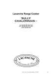
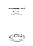
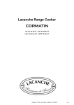
HOB TOP OPTION
INTEGRATED HOB ELEMENT
2 x 4 kW Burner
LAG 024 R
&
2 x 3 kW Burner
LAG 020 R
LAG020R-024R
- Ft 127a - GB - Rév 02- Modifié le
: 08/10/2013
1/18
CONTENTS
2 x 4 kW BURNER & 2 x 3 BURNER
TECHNICAL DATA SHEETS, MEASUREMENTS AND DIMENSIONS
—————————————————————————————————————————3
INSTALLER’S MANUAL
5
SITTING —————————————————————————————————————————7
GAS CONNECTION
—————————————————————————————————————————8
CHANGE OF GAS —————————————————————————————————————————9
ELECTRIC CONNECTION
—————————————————————————————————————————11
REPARATIES
—————————————————————————————————————————11
ELECTRIC CIRCUIT DIAGRAMS
—————————————————————————————————————————12
GAS LINE
—————————————————————————————————————————13
LAG020R-024R
- Ft 127a - GB - Rév 02- Modifié le
: 08/10/2013
2/18
TECHNICAL DATA
LAG 024 R & LAG 020 R : Cooking surface option with 2 burners located on left or right of central hob
(depending on model).
► 2 burners of different size and power (See B , C  : table 1 appendix 0).
► Controlled by a thermocouple safety valve .
► Mounted in a dished recess (stainless steel Z7CN 18.09).
► Electric push button ignition.
A
Pressures and hourly consumption :
Appliance gas supplying can be switched, please refer to rating plate and marking at the rear of the
appliance ( B , C  : table 3, appendix 0).
Accessories :
► Two 1/2 enamelled cast iron pan supports.
Directives :
Gas appliances : 2009/142/CEE.
Low Voltage : 2006/95/CEE.
CEM : 2004/108/CEE.
INSTALLER’S MANUAL
LAG020R-024R - Ft 127a - GB - Rév 02 - Modifié le : 08/10/2013
3/18
HOB TOP OPTION
2 x 4 kW Burner
LAG 024 R
2 x 3 kW Burner
LAG 020 R
INSTALLER’S MANUAL
Appliances must be installed in a workmanlike manner in accordance with the instructions in this manual
and locally applicable regulations.
This manual should be handed over to the user after installation.
LAG020R-024R
- Ft 127a - GB - Rév 02- Modifié le
: 08/10/2013
5/18
INSTALLATION / POSITIONING
A shut-off valve must be install and accessible close to the appliance in order to isolate it from the gas
applicable or to facilitate cutting the gas supply : Please ensure that installation complies with local
applicable regulations and standards
- Natural gas supply :
Mandatory to install an Automatic Shut-off Valve (since 1st July 1997 in France)
- LPG supply (butane, propane) :
Propane : Class 1 Safety Expansion Valve.
Butane : Butane safety expansion valve fitted to the cylinder (connected to the range by a LPG approved
hose, maximum length 2 metres).
INSTALLER’S MANUAL
LAG020R-024R - Ft 127a - GB - Rév 02 - Modifié le : 08/10/2013
7/18
GAS CONNECTION
Recommendations :
Ensure that the oven is set to the type of gas used (see label on the gas connector).
If the gas supply is not compatible with the gas setting of your range the setting must be modified. Refer
to the “Changing gas type” section of the present instructions.
Butane-fuelled units : Connect unit to 2.6 kg/h pressure reducer. Use two cylinders connected to a 3-way
valve ahead of the pressure regulator in case of prolonged, continuous duty.
Propane-fuelled units : Connect unit to a 3.0 kg/h pressure reducer. Use two cylinders and a 3-way
valve ahead of the pressure regulator in case of prolonged, continuous duty. The use of 37 kg or external
cryogenic tanks is both possible and recommended.
Before connection :
Check :
◊ That the gas supply pressure matches the gas pressure for which the range is set.
◊ Pipework is perfectly clean in order to prevent the injectors becoming blocked and malfunctioning of
the magnetic heads.
◊ The gas for which the appliance was set up : rating plate and markings.
◊ Cross-sectional area of gas supply pipework is compatible with the appliance’s thermal output.
◊ Correct fresh air flowrate (air supply sufficient to enable correct combustion to occur (see appendix 1).
Gas connection :
Male coupling Ø 15/21, 1/2” gas thread on ( see A / figure
1 ).
After connection :
Check the mains pressure at (see B / figure
2 ).
Check your connection is gastight.
B
1
2
A
INSTALLER’S MANUAL
LAG020R-024R - Ft 127a - GB - Rév 02 - Modifié le : 08/10/2013
8/18
CHANGING GAS TYPE
Lacanche ranges are supplied with the appropriate gas fitting for the gas type specified when the
order is placed. However, the setting must be fine tuned (COMMISIONED) when the cooker is
installed.
The cooker is designed to operate with the gases in table 4, appendix 0.
IMPORTANT : Close the mains gas valve before carrying out any works.
IMPORTANT
In case of use with a gas other than that for which the cooker was initially set up, it is crucial to replace the injectors and modify the adjustments as defined below.
CHANGING GAS TYPE (Changing the Jets on a Gas Cooker)
HOB :
Lift the air ring up to reveal the injector (see A , figure 1 ).
► Replace the injectors (see B , figure 1 ) in accordance with table 5 in appendix 0 ( Ø in 1/100
mm).
►
If necessary, the mixer tubes of the lateral burners maintained by a cross-bar (see C , figure 2 ),
may be released.
To release the tubes loosen screws (see D , figure 2 ) and then screw (see E , figure 3 ).
Note: Ensure that new jet is fitted with a new washer, and tighten into place.
Adjusting the primary air :
Put the burner in place and ignite it.
► Lower the air ring to appropriate level for that gas type (see
(flame should be crisp, blue without any yellow).
►
F , figure 4
), tabel 6 in appendix 0.
A
B
C
D
2
1
wrench, 12
F
E
3
INSTALLER’S MANUAL
LAG020R-024R - Ft 127a - GB - Rév 02 - Modifié le : 08/10/2013
4
9/18
CHANGING GAS TYPE
Comissioning (fine tuning) gas burner :
After connection or changing gas type, it is imperative to adjust for a fine tuning.
► Ignite all the burners on the hob.
► After a couple of minutes, reduce to lowest setting.
► Remove control knob by pulling it off (see G /figure 5 ).
► Using a flathead screwdriver adjust the simmer flame accordingly (see G , figure
5 ).
Note: The flame is reduced to ¼ when you turn maximum to minimum. Looking for a crisp
blue flame without any yellow which does not go out when turned from maximum to minimum.
Setting the safety thermocouple (Hob) :
If the burner goes out, having kept the control knob pushed in for roughly twenty seconds, check
that :
- The magnetic head grips the valve moderately, finger right.
- The flame touches the point of thermocouple (see H , figure 6 ).
- The thermocouples and magnetic heads are absolutely clean.
Remove control knob by pulling it off (see H figure 6 ).
Using a flathead screwdriver adjust the simmer flame
G
H
5
INSTALLER’S MANUAL
LAG020R-024R - Ft 127a - GB - Rév 02 - Modifié le : 08/10/2013
6
10/18
ELECTRIC CONNECTION
See parts «Electric Connection» on the cooker installer’s Manual.
SERVICING/ REPAIRS
All work on or repair of an appliance must be carried out by a qualified engineer.
Greasing gas valve (Hobs and Ovens) :
The valve may lose its grease through use. It is therefore necessary to grease the valve in order to make
it leaktight and facilitate turning.
1 - Shut off the valve and / or the main electrical supply of the unit.
2 - Take out the knob corresponding to the gas valve to be greased.
3 - Unscrew the head from the body of the burner valve.
4 - Grease the tap shaft (high temperature lubricant, for example : SILICAL GEL ™ BARBAHL).
Caution ! Any excess grease should be removed.
Reverse operation 3 to 1 (in that order) to put valve and knob back on.
Electric Limiting thermostat :
In accordance with the construction regulations, the limiting thermostat is intended to protect the range
from overheating.
In the event of overheating the limiting thermostat is triggered and cuts out the range’s oven functions.
The advanced technology used in the limiting means that it is very sensitive to impacts and vibration that
may occur during transport and handling.
The limiter may therefore be unexpectedly triggered when the oven is first heated and stop the oven
from working.
To reset limiting thermostat for electric ovens with :
Gas hob :
1- Remove the ventilation strip from the rear of the hob.
2- Unscrew the cover protecting the knob.
3- Press the knob marked (see
A / figure 1
).
Electric hobs :
The button is behind the ventilation strip .
To have access there, it is necessary to use a small screwdriver to press on the push-button and reset
limiting thermostat (see B / figure 2 ).
B
A
1
INSTALLER’S MANUAL
LAG020R-024R - Ft 127a - GB - Rév 02 - Modifié le : 08/10/2013
2
11/18
ELECTRIC CIRCUIT DIAGRAMS
For references and descriptions of the various components refer to table 9 in appendix 0
2 x 4 kW & 2 x 3 kW Burner Ignition
L
N
1
2
X
A
S1
1 2 3 4
5 6
B
Note: Ignition controller terminal lugs not in use are to be grounded.
INSTALLER’S MANUAL
LAG020R-024R - Ft 127a - GB - Rév 02 - Modifié le : 08/10/2013
12/18
GAS CIRCUIT
For references and descriptions of the various components refer to table 10 in appendix 0
65.39895
1,5 kW = 65.330001
3 kW = 65.330002
4 kW = 65.330003
65.226006
1,5 kW = 65.064007
3,0 kW = 65.064007
4,0 kW = 65.064007
5,0 kW = 65.064007
1,5 kW = 65.640003
3 kW = 65.640004
4 kW = 65.330005
65.080005
65.033018
65.39895
65.226006
65. 430007
65.51114
65.32638
88.31942
INSTALLER’S MANUAL
LAG020R-024R - Ft 127a - GB - Rév 02 - Modifié le : 08/10/2013
13/18
HOB TOP OPTION
2 x 4 kW Burner
LAG 010 UR
2 x 4 kW Burner
LAG 010 UR
USER’S MANUAL
IMPORTANT
It must be installed in accordance with the applicable regulations and standards in an adequately
ventilated room.
Any changeover to a gas other than that for which the cooker is set up must be carried out by a qualified
installer.
Any changeover to a voltage other than that for which the cooker is set up must be carried out by a qualified
engineer.
WARRANTY
The warranty is stated on the sales contract. Please contact your approved Dealer if any work has to be
carried out under warranty.
This warranty excludes damage resulting from incorrect installation, improper use or inadequate servicing.
- Ft 127a
LAG020R-024R
- GB - Rév 02 -Modifié le : 08/10/2013
15/18
GAS BURNER
Highly valued by chefs because of their fast heating and ease of use, gas flame burners have always
been traditional heat sources for cooking in large kitchens. Other heat sources have appeared in
recent years but just as many users still prefer gas. It offers many advantages; gas provides a
fast increase in temperature. The height of the flame can be checked easily at a glance in order to
increase or reduce its power. Accessories such as wok rings and simmer & griddle plates may be
used over gas burners.
Lacanche gas hobs for cook’s stoves are fitted with burners of different power. These automatically
stabilised flame burners offer a very low slow setting to facilitate simmering or high heat for quick
sealing. Depending on their rating, they are suitable for various types of utensils.
Fast and intensive burners : are ideal for shallow frying pans, saucepans and cooking pots. Their
high output provides very fast increases in temperature and very flexible use.
You will quickly learn how to use the various types of burners to achieve optimum cooking.
Description :
The burners are arranged on a stainless steel hob.
Each burner is fitted with a thermocouple safety cut-out.
This device switches off the gas supply if the flame is accidentally extinguished.
The various types of burners can be identified by their respective diameter.
►
Designation
Diameter of the burner cap
Power
Intensive
Ø 90 mm
4 kW
Fast
Ø 72 mm
3 kW
Use :
Simultaneously press in and turn the burner dial anti-clockwise to setting .
Press the ignition button while maintaining pressure on burner dial for about 20 seconds to ignite
burner and initialise safety thermocouple.
A reduced flowrate position identified by the mark produces the preset minimum burner power (low
flame).
To turn off, turn the control knob clockwise to the « » position.
The control knob returns to its initial position, the latching mechanism operates
and the gas safety cut-out is activated several seconds after the burner goes
out.
Useful hint
Always choose a burner that matches the diameter of the utensil used.
CAUTION : During use of the cooking surface, accessible parts may
become very hot during use. Warn users of the potential risks.
MANUEL
D’UTILISATION
CLEANING AND MAINTENANCE
Before any cleaning work, close the gas supply and/or isolate from
the mains electricities supply
Do not use a steam cleaner to clean the range.
Gas hobs :
The burners are made in two parts in order to facilitate cleaning. Clean them separately,.
→ Burner cap :
Burner caps are made of solid brass. Use a special brass-cleaning product (e.g. MIROR® or
BRASSO®) and a soft cloth.
If the product runs onto the enamel do not rub (these products generally contain
abrasives). Rinse immediately with clean water without rubbing.
If the caps are very dirty polish them with very fine sand paper and then rub them with a copper
cleaner.
→ Burner body :
The aluminium bodies of the burners become stained with use. They should be cleaned regularly
with a scouring pad (Scotch Brite®).
After removing the pan supports and burners, the cooking surface can be cleaned easily and
thoroughly by simply using a sponge.
Do not use scouring pads or abrasive products such as oven cleaners and stain removers.
When cleaning, be careful not to splash liquid into the openings of the burners.
MANUEL
D’UTILISATION