1
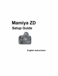
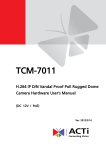
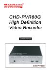
IP-B9515SNTLA User Manual 1 INSTALLATION 1. 1.1 Minimum System Requirements CPU Pentinum 4 2.4GHz and above Hard Disk 40 GB or above Memory 256 MB or above Operating System Windows XP with SP2 or above Video Resolution SVGA or XGA with 1024x768 resolution 1-1 1.1.1 Product and Accessories IP-B9515SNTLA Body Manual & S/W CD Cross LAN Cable Accessory Pack <Picture 1> Product and Accessories 1.1.2 Physical Description ① ② ③ ④ ⑤ 1. Power Input 12 Volts DC: Please follow the instructions on the connector 2. Analog Video Output The Camera Supports 1 channel of analog video output 3. Audio Input Sensitivity:-42dB±3dB(0dB=1V/Pa at 1KHz) S/N Ratio:More than 58dB Directivity:Omni directional 4. Audio Output The IP device supports audio output with earphone jack 5. Ethernet Port: The camera connects to the Ethernet via a standard RJ45 connector and can auto detect the speed of the local network segment (10Base-t/100Base-TX Ethernet). 1.2 Preparation before setup To configure your IP device, you have to use the Internet Explorer to login. Before that, your PC’s networks settings and the IP device’s IP address must be setup. Make sure all the connections are connected correctly, and then follow the procedures below to setup. 1. Setup your PC network You have to match your PC’s TCP/IP setting with the IP device’s default settings before you can use IE browser to login it. This section tells you how to setup your PC’s TCP/IP settings. 2. Setup IP device’s IP address This IP device’s IP address can be setup manually or automatically by network service (DHCP). If it acquires the IP address by using the DHCP service, please use the IP utility software bundled in the product CD to search all the IP devices’ IP address. 1.2.1 Setup your PC network To set up the network of IP device via a PC, you have to change the TCP/IP settings of the PC. The following are the default network settings of IP device. IP Address: 192.168.0.100 Subnet Mask: 255.255.255.0 To access the IP device, the IP address of the PC should match the address below. IP Address: 192.168.0.xxx Subnet Mask: 255.255.255.0 NOTE: xxx should be a number from 1 to 254, but 100 is excepted. 1-2 The procedures below is the setup procedure of a PC using Windows XP as its OS. When running an OS other than Windows XP, please refer to the manual included with the OS. 1-3 z STEP1 Start up your PC. z STEP2 Click the [Start] and select the "Control Panel" z STEP3 Double-click the "Network and Internet connections" icon. z STEP4 Double-click the "Network connections" icon 1-4 z STEP5 Click “Local Area Connections”, and then click “Change settings of this connection” in the network Task menu. z STEP6 Click “Internet Protocol (TCP/IP)”, and then click the [Properties] button. 1-5 1.3 Configuring the IP device This section describes how to configure the IP device. The product administrator has unlimited access to all setup windows and normal users can only watch the live image. The IP device is configured under a standard browser (Microsoft Internet Explorer 6.0 or above). Follow the procedures below to configure the IP device. z STEP1: Open a browser z STEP2: Enter the IP address of the IP device. The default IP address is “192.168.0.100” The “Login Page” is now displayed as below. z STEP3: Enter the Account name (factory default: Admin) and the Password (factory default: 123456). NOTE: Internet Explorer of 6.0 or above is highly recommended. If you don’t have the it, please download it from http://www.microsoft.com/windows/ie/downloads/default.mspx 1-7 z STEP4: Select the language of the IP device user interface. You can select from English, Traditional Chinese, Simplified Chinese, Japanese, Spanish, Italian, German, Portuguese,Czech and French. This user interface setting will disappear once you log out, if you want to change the default user interface language, please change the setting of [Host setting] after login successed. z STEP5: Click the to re-enter again. button to login or click the button Once successfully login, the “Video Display page” will be displayed as below. 1-8 1.3.1 Video Display This section tells you how to view live images via Internet Explorer. z STEP1: Click the [Video Display] on the “Main Setup page”. The “Video Display page” is displayed as below. z STEP2: Check the [MPEG4/MJPEG] to Select the Compression type. Once selected, the video server/IP camera will start to stream with new compression type. z STEP3: Click the [Scale Down] checkbox to scale down the SXGA(1280x1024)/720P(1280x720) to VGA resolution. z STEP4: Check the [Mute] checkbox to mute or display audio from the video server/IP camera. z 1-9 STEP5: Click the [Audio Out] checkbox to enable/disable audio transmission from this PC to IP device’s audio out and change audio out volume. Ex: while this function enabled you can talk to the people at the IP device site. z STEP6: Click the Setup page”. [Quit] to exit the live view and return to “Main z NOTE: If the streaming is disabled, you cannot see the live images here. NOTE: Be sure to set the Network Connections Type to Auto Negotiation to respective apparatus connected to this IP device via network. Otherwise, the maximum transmission performance might not be achieved. This is because the IP device follows MII standard. 1-10 1.3.2 Host Setting This section tells you how to setup IP device’s host settings and LAN settings. z STEP1: Click the [Host Setting] on the “Main Setup page”. The “Host setting page” is displayed as below. z STEP2: Configure these settings with reference to the table below. If you are still unsure what to set, contact your system administrator. ■Host Setting Parameters Host name Language 1-11 Description Enter a host name, and this host name will be shown when you use the IP utility or the SDK to search for the IP device. Select the language of default user-interface. Each user login will see the default user-interface first. ■Network link speed & duplex Parameters WAN port Description This item lets you select the network transmission speed of WAN port. You can select from 1. Auto detect (default setting) 2. 100Mbps / Full duplex 3. 100Mbps / Half duplex 4. 10Mbps / Full duplex 5. 10Mbps / Half duplex ■Port Mapping Parameters TOS (type of service) TOS priority Description Select whether to add the TOS tag onto the streaming data. Streaming data with a higher priority TOS tag will be transmitted first while compared with other data to be transmitted. Select the TOS tag’s priority to be added onto the streaming. You can select between 1. Normal-Service 2. Minimize-Cost 3. Maximize-Reliability 4. Maximize-throughout 5. Minimize-Delay ■ToS (Type of Service) Parameters Description HTTP port Select the port for this IP device to use HTTP protocol. Search server port1 Search server port2 Select the port1 for this IP device to support search function of the application program (eg. IP utility). Select the port2 for this IP device to support search function of the application program (eg. IP utility). z STEP3: Click the [Apply] button of each setting to confirm the settings or click the [Reset] button to re-enter the parameters. NOTE: Once finished all settings, be sure to click the [Save Reboot] button, otherwise, some settings won’t take effect. NOTE: Check with your system administrator, if Client PC and IP device are setting in different VLANs, please connect to WAN port. NOTE: Be sure to set the Network Connections Type to Auto Negotiation to respective apparatus connected to this IP device via network. Otherwise, the maximum transmission performance might not be achieved. This is because the IP device follows MII standard. 1-12 1.3.3 WAN Setting This section tells you how to setup IP device’s WAN, DNS server and DDNS server settings. z STEP1: Click the [WAN Setting] on the “Main Setup page”. The “WAN setting page” is displayed as below z 1-13 STEP2: Configure these settings with reference to the table below. If you are still unsure what to set, contact your system administrator. z STEP7 Click the “Use the following IP address” radio button and enter the IP address and the subnet mask. Please set the settings as below. IP address: 192.168. 0.xxx Subnet mask: 255.255.255. 0 (NOTE: xxx should be a number from 1 to 254, but 100 is excepted.) z STEP8 Click the [OK] button and the window dialog box closes. 1-6 ■WAN Setting Parameters Dynamic IP address Description Click this to enable IP device’s DHCP function. It will acquire its WAN port IP address from a DHCP server within the same network. (You must have a DHCP server in order to enable this function.) Click this to manually enter the IP device WAN port IP address. IP address: Enter the WAN port IP address. Static IP Subnet mask: Enter the subnet mask of WAN port. If IP address is changed, adjust the subnet mask accordingly. address ISP gateway: Enter the IP address of the gateway (the router). Click this when you connect IP device directly to the xDSL modem. User name: Enter the user name of your xDSL account. PPPoE Password: Enter the password of your xDSL account. Note: You have to click the [Save Reboot] after you click the [Apply button] to let this IP device start xDSL connections. ■DNS server Setting Parameters Primary DNS server Secondary DNS server Description Defines the IP address of the primary DNS server. This is used for identifying this computer by name instead of IP address. The IP address of the secondary DNS server. It will be used once the primary DNS server fails. ■DDNS server Setting Parameters DDNS type Service ISP Host name z 1-14 Description Click this to enable IP device’s DDNS function. DDNS function enables user to connect to this IP device by domain name even if its IP address is not static. Click one of the DDNS service providers. You can visit their website to get a DDNS service account for this IP device. Enter the host name of your DDNS service account. (ex: xxxx.dyndns.org) User name Enter the user name to login your DDNS service account. Password Enter the password to login your DDNS service account. STEP3: Click the [Apply] button of each setting to confirm the settings or click the [Reset] button to re-enter the parameters. NOTE: Check with your system administrator, if Client PC and IP device are setting in different VLANs, please connect to WAN port. NOTE: Once finished all settings, be sure to click the [Save Reboot] button, otherwise, some settings won’t take effect. NOTE: Be sure to set the Network Connections Type to Auto Negotiation to respective apparatus connected to this IP device via network. Otherwise, the maximum transmission performance might not be achieved. This is because the IP device follows MII standard. 1.3.4 Date Setting This section tells you how to setup IP device’s date and time settings. 1-15 z STEP1: Click the [Date Setting] on the “Main Setup page”. The “Date setting page” is displayed as below z STEP2: Configure these settings with reference to the table below. If you are still unsure what to set, contact your system administrator. ■Date Setting Parameters SNTP/NTP server Description Click this to enable IP device’s SNTP/NTP function. SNTP/NTP function enables this video to synchronize its time settings with a SNTP/NTP server. You can use this function to make sure all your IP devices’ time is the same. Additionally, with our embedded digital-time-code in the streaming, you can tell the event sequence accurately. IP address: Enter the IP address of the SNTP/NTP server. Sync time: Select the time interval for this IP device to synchronize its time. Click this to manually setup the date & time. Set manually Date : Select the date Time: Select the time Time zone Select the time zone offset for local settings Select Type 1 to specify daylight saving time by week number in a month; select Type 2 to specify daylight saving Day Light Saving time by date. Start Time : Select the daylight savings start time. 1-16 End Time : Select the daylight savings end time. z STEP3: Click the [Apply] button of each setting to confirm the settings or click the [Reset] button to re-enter the parameters. NOTE: Once finished all settings, be sure to click the [Save Reboot] button, otherwise, some settings won’t take effect. Manually set date and time will be gone, if power off. 1-17 1.3.5 Video Setting This section tells you how to setup IP device’s video and streaming settings. z STEP1: Click the [Video Setting] on the “Main Setup page”. The “Video setting page” is displayed as below ■Video setting Parameters Camera name Description The camera name is reserved for customer use. Select the streaming mode. 1. TCP only 2. Multicast only Streaming Method 3. RTP Over UDP 4. RTP Over Multicast 5. RTP Over UDP & Multicast RTSP Authen Checkbox to enable RTP streaming’s Account/Password authentication. Enable 1-18 RTP B2 Frame Enable Checkbox to enable the B2 frame in RTP streaming Audio Select enable or disable the audio function. Input Sensitivity Select HIGH or LOW of the audio input sensitivity Multicast IP Select the multicast IP. Default settings is 228.5.6.1 Multicast TTL Select the multicast TTL. Defualt setting is 255. IGMP Select video type connected to the video-in of this IP device. If you use an incorrect video type, some images might be lost. Resolution Select the video resolution of the IP device. Select the frame rate mode. Constant: The streaming’s frame rate remains constant at all conditions. Frame rate mode Variable:: The streaming’s frame rate will variants according to the images variability to keep the image quality good. Frame rate Encoder Type Video Bitrate Mode Video Maximum Bitrate Bitrate Serial Port Baud Rate Select the frame rate of the video streaming. Select the encoder’s compression type. 1. MPEG4 2. MJPEG Select the video bitrate mode. Constant Bit Rate: The streaming’s bitrate remains constant at all conditions. Variable Bit Rate:: The streaming’s bitrate will variants according to the images variability to keep the image quality good. Select the Miximum bitrate of the video straming. Designating a limited bit rate may reduce frame rate. Doing so will also disable Bit Rate setting below. Select the bit rate of the video streaming. You can select from 28Kbps to 3Mbps. Note: Lower bit rate consumes less bandwidth but delivers lower quality images. High bit rate consumes more bandwidth but delivers higher quality images. Select the Baud Rate setting of serial port. Serial Port Control Select the Control setting of serial port. RTSP port Select the port for this IP device to support RTSP Video RTP Over Multicast Audio RTP Over Multicast Enable/disable the multicast video streaming via RTP protocol Enable/disable the multicast audio streaming via RTP protocol Select the port for this IP device to support video control Video control port function of the application program. Video streaming Select the port for this IP device to support video streaming function of the application program. port (TCP Only) Video multicast Select the port for this IP device to support video multicast function of the application program. port (Multicast 1-19 Only) STEP3: Click the or click the 1-20 [Apply] button of each setting to confirm the settings [Reset] button to re-enter the parameters. 1.3.6 Video Adjustment This section tells you how to adjust the streaming video. z STEP1: Click the [Video Adjust] on the “Main Setup page”. The “Video adjust page” is displayed as below z STEP2: Set the checkbox to enable motion detection function. z STEP3: Set the sensitivity of motion detection windows. z STEP4: Set the interval time of motion detection windows. Within the interval time after the motion detection is triggered, no motion detectioin will be triggered. z STEP5: When satisfied with the motion settings, click the z STEP6: Adjust the video by changing the value of [Set] “Brightness”, “Saturation” and “Contrast”. See the images displayed above for the effect of the current setting. z 1-21 STEP7: When satisfied with the video settings, click the [Apply] button of each setting to confirm the settings or click the [Reset] NOTE: Please note that “Hue” setting doesn’t support by SuperCMOS product. NOTE: Once finished all settings, be sure to click the [Save Reboot] button, otherwise, some settings won’t take effect. NOTE: You may find a support package for helping you on better video quality adjustment. Please visit our web site, and get the support document TS-00103. 1-22 1.3.7 Camera Setup (SuperCMOS model only) This section tells you how to adjust the camera. z STEP1: Click the [Camera Setup] on the “Main Setup page”. The “Camera Setup page” is displayed as below ■Camera setting Parameters Description Video Flipping Checkbox to flip the video. Video Miirror Checkbox to mirror the video. Lens Compensation NightTime Gain Threshold Checkbox to load the best video setting for bundled lens. Select the nighttime gain threshold. Select the white balance mode. After you set the White Balance Mode 1-23 parameter, you need to wait for 5~10seconds to see the final result. 1. AUTO : Auto white balance (default) 2. INDOOR1: Select the indoor white balance profile 1. 3. INDOOR2: Select the indoor white balance profile 2. 4. OUTDOOR1: Select the outdoor white balance profile 1. 5. OUTDOOR2: Select the outdoor white balance profile 2 6. HOLD CURRENT: Select this to let the IP camera automatically obtain a best white balance setting according to current environment. The IP camera will use this setting to adjust color. NOTE: This setting will be lost after you reboot the camera. 7. MANUAL: Select this to enable manual setting of the white balance. You will need to enter the R Gain and B gain setting below. R Gain (Manual White balance mode only) B Gain (Manual White balance mode only) Exposure mode Exposure Gain Shutter Speed AGC Gain mode only) Maximum Auto Shutter Speed (In auto Exposure mode only) Flickless Mode STEP2: Click the 1-24 Add or decrease blueness to the video when under Manual White Balance mode. (This function is only available in Manual White balance mode.) Select exposure mode to auto or manual. - Auto: The IP camera will adjust the exposure automatically. - Manual: (In Manual White balance mode only) Manually select the Exposure Gain and Shutter Speed below. Select the exposure Gain of the IP camera. The higher the value = brighter images. Increase or decrease the shutter speed. The closer the number is to 1, the better nighttime performance is, although this also causes motion blur to the video. When exposure mode is auto, IP camera will adjust its shutter speed according to AGC gain and the Maximum auto shutter speed. Higher AGC gain = brighter images. (In auto Exposure or click the Add or decrease redness to the video when under Manual White Balance mode. (This function is only available in Manual White balance mode.) When exposure mode is auto, IP camera will adjust its shutter speed according to AGC gain and the Maximum auto shutter speed. This setting is to set the maximum shutter speed range of this camera. Change settings between 60Hz or 50Hz, depending on the AC power type of your region. [Apply] button of each setting to confirm the settings [Reset] button to re-enter the parameters. 1.3.8 User Account Management This section tells you how to setup the accounts. z STEP1: Click the [User account] on the “Main Setup page”. The “Account management page” is displayed as below z STEP2: Setup the account names and their respective passwords. There are 1 root (administrator) account and 10 common user accounts. Administrator account allows the user to watch the live view and setup everything; but common user account allows user only to watch the live image. z STEP3: Click the settings or click the [Apply] button of each setting to confirm the [Reset] button to re-enter the parameters. NOTE: Once finished all settings, be sure to click the [Save Reboot] button, otherwise, some settings won’t take effect. 1-25 1.3.9 System Info This section tells you how to see the system information of this IP device including system information, WAN status and system log. z STEP1: Click the [System info] on the “Main Setup page”. The “System information page” is displayed as below z STEP2: View the information at the 3 columns. This information is very useful to understand the IP device status and to resolve any problem that might occur. ■System info Column System info WAN status System log 1-26 Description It shows the firmware version, MAC address, production ID, and factory default type of IP device. It shows the WAN port’s IP address, netmask, gateway, DNS server, DDNS host and connection status. It shows the system event. This column is very useful to as a diagnostic tool. z STEP3: Click [Parameter List] where you may see all configurations of the IP device. z 1-27 STEP4: Click [Server Report] to export related information of the IP device while reporting a support to your support channel. 1.3.10 Firmware Upgrade This section tells you how to see update IP device’s firmware. You can always visit our web site for the latest firmware. z STEP1: Click the [Firmware] on the “Main Setup page”. The “Firmware upgrade page-1” is displayed as below z STEP2: Click [Apply] button. The ‘’firmware upgrade page-2” will be displayed as below. ■Date Setting Parameters Firmware images file 1-28 Description You can upload the firmware images here. Click the [browse] to select the an image file and click the [enter]. 1.3.11 Factory Default This section tells you how to see load IP device’s factory default setting. z STEP1: Click the [Factory Default] on the “Main Setup page”. The “Factory default setting page” is displayed as below 1-30 z STEP2: Click the [Apply] button to go to loading confirmation page or click the [Reset] button to exit to previous page. z STEP3: A confirmation page will be displayed. Click the [Save Reboot] button to start loading factory default settings. 1.3.12 Save Reboot This section tells you how to save all the settings and reboot this IP device. This is critical because some settings might not take effect before save and reboot. z STEP1: Click the [Save and reboot] on the “Main Setup page”. The “Save and reboot page” is displayed as below. z 1-31 STEP2: The Action LED indicator will light down to indicate that the IP device is rebooting. After around 30 seconds, the Action LED will light up again to indicate that the reboot is completed. You can always get the latest version at our website. MD5 file z z You can upload the MD5 file here. Click the [browse] to select an MD5 file and click the [enter]. You can always get the latest version at our website. NOTE: The version of the firmware image and the MD5 file to be uploaded must be the same, otherwise, the firmware upgrading will fail and the IP device will continue using previous firmware version. STEP3: Click the [Upload] button to start upgrading, or click the [Reset] to re-select the files, or select z 1-29 to cancel the process. STEP4: The upgrade process window shows a progress bar indicating upgrade status. When the upgrading is completed, the system will reboot. 1.3.13 Logout This section tells you how to logout the IP device. Be sure to logout this IP device once your setting is completed. z STEP1: Click the [Logout] on the “Main Setup page”. You will logout and return to the “Login Page” displayed as below. 1-32 2. Camera Configuration Internal Components LED VOLUME VIDEO TEST CONNECTOR OSD JOYSTICK SWITCH UP SET RIGHT LEFT DOWN Push the Joy stick for one second, and the OSD appears on the screen. Move the Joy Stick up, down, left & right to control the OSD functions. Function LENS DC MANUAL SHUTTER AUTO FLK OFF ON OFF ON FIXED MANUAL FIXED MANUAL BLC AGC WHITE BAL. ATW AWB FUNCTION RETURN CAMERA ID ON OFF MIRROR ON OFF DAY / NIGHT COLOR MOTION DET ON PRIVACY ON GAMMA 0.05~1.00 LANGUAGE ENGLISH RESET ADJUST CONTRAST SHARPNESS CB_GAIN CR_GAIN RETURN RETURN AUTO B/W OFF OFF USER 한국어 汉语 漢語 日本語 2.1 Product Specification Image Sensor 1/3" Sony Super-HDD CCD, 410,000 pixels NTSC 768(H)*494(V) PAL 755(H)*582(V) Effective Pixel Horizonal resolution 540 TV Lines 0.00 Lux(LED ON) Minimum Illumination S/N Ratio 50dB(Weight On) IR DISTANCE 2.8~11mm(9~22mm)-40M (48LED)/5~50mm-80M (10GIANT LED) 2:1 Interlaced 525 Lines / 60Fields / 30Frames Scanning System Synchronization Internal Compression MPEG-4 SP Compliant Gain Control On / Off IMAGING Electric Shutter Speed 1/60 ~ 1/120,000sec Back Light Compenstion (BLC) Auto / Off W-ATW / FIXED / MANUAL White Balane Maximum Aperture Ratio 1:1.3~2.0 720*480 720 * 576 624*480 624 * 576 352*240 352 * 288 176*120 176 * 144 Up to 8 fps @ SXGA Up to 8 fps @ SXGA Up to 10 fps @ HS720 Up to 10 fps @ HS720 Up to 30 fps @ VGA Up to 30 fps @ VGA Image Sizes (NTSC/PAL) Image Frame Rate Auto D/N YES On Screen Display(O.S.D) Motion Detection Yes Web Viewer CONTROL Built-in Microsoft Internet Explorer 6.0 or above Software Security Password Protection: Configured by the Administrator HTTP, FTP, SMTP, TCP, IP, DHCP, ICMP, NTP, DNS, DDNS,UDP, Protocols Network PPPoE,RTP,RTSP,IGMP,ARP,3GPP Ethernet Ethernet(10/100 Base-T), RJ45 Connector Bi-Directional Yes Compression 8kHz, Mono, PCM Audio Video Output Dimension 1.0 Vp-p 75 ohm Composite 100(φ) * 296mm(L) PHYSICAL Power Source Power Consumption (Max.) Operational Temperature Weight DC 12V / POE(802.3af support) 4.8W -10 deg ~ +50 deg C RH95% MAX(14 deg F to 122 deg F) 1.5kg