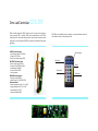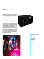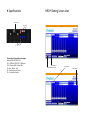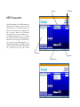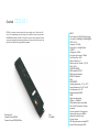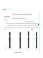
1
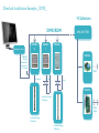
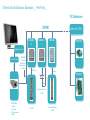
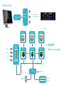
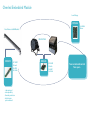
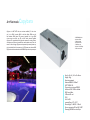
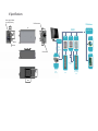
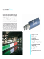
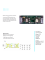
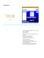
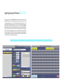
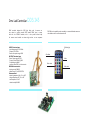
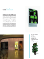
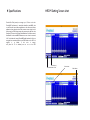
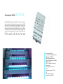
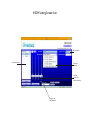
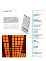
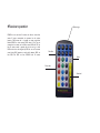
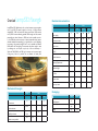
MADE IN ITALY
Professional control led lighting
About us
Overled it is a Brand name of DDS elettronica srl.
Overled design and develop electronics solution for LED
application since 2002, switching power supply, costant
current controls, embedded electronics and LED.
Overled have produced several tousand controller in the
years ,where our elctronics and led lamp found apllication
in several different field as , Cruise boat (last generation)
with switching power supply , TV stages all Italian television
are using Overled products , Hotels , restaurant ecc.
Overled develop more than 50 new projecy per year ,
DMX controller , DALI , ART NET NODE , BUS
system (DoMONET) power supply and DMX ,
intelligent lamp solution ,or customized application on
customer request. Overled is serving the best illumination
customer giving all kind solution electronic and led to help it’s
customer
on
LED
LAMP
design
process.
Overled it’s also a partner for design and installation of
big illumination system LED based , helping it’s customer
on
design
and
develop
installation.
OverLed Installation Example_ DMX_
>32devices
DMX/RDM
Lighting Control
DDS453
V
DDS453
I
DMX SPLITTER
DDS344
DDS166
DMXOUT
Overled
Dmx Cable
balanced up
to 1200mt
DMX
4/5wires
48 led
4wires
DDS378
Constant Current
150W max
DMX/
RDM
Constant Voltage
250W max
Constant Voltage
150W max
OverLed Installation Example _ Art-Net_
>32devices
DMX
DDS453
V
DDS453
I
DMX SPLITTER
DDS344
DDS166
Lighting Control
Hub Ethernet
Artnet
DMXOUT
Overled
Dmx Cable
balanced up
to 1200mt
4/5wires
4wires
48led
Constant Current
< 150W
CAPYBARA
- Artnet
- Dmx out
- Dmx recorder
- RDM
< 250W
Constant Voltage
<150W
DDS378
OverLed Bus
Ethernet
HUB
Lighting Control
To Artnet Nodes
(Overled Bus Pilot)
LAMP..
RDM
DDS453
V
# 32 MAX
#1
LAMP..
LAMP..
< 5OOW
PILOT
DRIVER
DRIVER
DRIVER
300mt wires lenght
Artnet
Dmx IN
Dmx OUT
DDS453
I
sd memory
2 wires no polarity
OVERLED BUS
NODE
Constant
Current
32 MAX
Constant
Voltage
Overled Embedded Module
Low Voltage
DDS386
24-48Vdc
Driver
Your Fixture is a Wall Washer?
YOUR FIXTURE
DDS309
3X12LED
350mA
220VAC
50/60Hz
- dmx protocol
- rdm capability
- thermal protection
- all electronic
opto insulated
DDS243
4X12LED
350mA
220VAC
50/60Hz
Your customized control
Your specs...
Art Net node
Capybara
Capybara it is ART NET node, one universe available (512 dmx channel), it is a DMX recorder, DMX to Art Net Node, RDM over Art
Net interface, DMX player. SD memory (optional) for a large DMX
show storage, one show per SD, no multi show selection available.
Capybara it is compatible with Art Net node protocol for setting IP, broadcast please use Esuite or Jartnet405 from www.overled.com site, the software it is free of charge. Capybara can be powered by external power supply (not included) with it’s connector or by POE power over ethernet HUB.
Capybara it can be mounted on electrical DIN BAR or by velcro strips on request.
- RDM/DMX/ArtNet
- ArtNet to DMX
- DMX to ArtNet
- ArtNet Recorder
- DMX Recorder
- ArtNet + DMX Player
- RDM over ArtNet
Size: (L x W x H ) 140 x 42 x 60 mm
Weight: 100gr
Aluminium satinated
Ethernet IEEE 802.3 10Base-T
USITT DMX512 B
Play record one universe DMX512
ArtNet to DMX / DMX to ArtNet
RDM over ArtNet
2GB microSD card
IP 30
Hr 30 a 85%
operating Temp -5°C + 50°C
Power supply 12- 48 VDC – 500 mA
Power consumption 350 mA @ 12 VDC
Mounting DIN BAR or velcro strips
# Specifications
Power supply 12-48vdc
no polarity necessary.
9 12
23
DMX
DMX SPLITTER
60
38
38
22
142
9 13
>32devices
DMX connection
23
12
DDS453
V
DDS453
I
DDS344
DDS166
Lighting Control
Din Bar
10 4
Artnet
Ethernet
41
SD card slot
Overled
Dmx Cable
balanced up to 1
200mt
4/5
4
48
Constant Current
=
=35,30
< 150W
=46,80
=
CAPYBARA
- Artnet
- Dmx out
< 250W
Constant Voltage
<150W
DDS378
Usb-Dmx/Rmd
Ecco
ECCO Ready Steady Go device can be defined and classified as the”
lingua franca “(universal-translator) for all users of USB/DMX/RDM protocols. ReadySteadyGo is totally compatible with standard E1.20 RDM &
DMX USITT 1990. ReadySteadyGo is opto isolated and can be powered
directly from any PCUSB port (Mac too). This device is totally free-electric
interferences between DMX & PC. Should the device, inadvertently, be
d i s c o n n e c t e d a n d i m m e d i a t e l y reconnected, the software will
instantly reinstate connections. The hardware of the ColoursReadySteadyGo is robust and ergonomically designed to be handled without any fear
of breaking if incidentally dropped. Colours Ready Steady Go has been
designed to facilitate RDM bi-directional communications using the 2-core
DMX protocol. Colours Ready Steady Go integrates the discovery RDM
protocol that identifies all fixtures connected with DMX protocol.
The Colours Ready Steady Go is also the perfect interface DMX pass
thorugh gear compatible with the majority of all existing world’s software
Power Supply from PC 200mA
DMX USITT compliance
RDM e 2.0 compliant
DMX optoinsulation :
2500VRMS Bus Isolation OnChip
hight voltage Capacitor
+4.5V to +5.5V Power-Supply VoltagRange (Usb)
±15kV ESD Protection
Hot-Swap-Protected Driver-Enable Input
Undervoltage Lockout
Isolation-Barrier Fault Detection
Short-Circuit Protected
Thermal Shutdown
Open-Line and Shorted-Line Fail-Safe Receiver
# Specifications
# RDM Setting Screen shot
Device personality
DMX on/OFF
30mm
DMX address
device
115,40mm
DMX mixer activation key, 512 slider appare on screen the selected value is sent
Blink the device found on the DMX network to identify position
Start the device Finder on DMX network RDM compatible
DDS.555
DDS555 it is constant voltage controller,3 channel. This module can
work in several mode DMX/RDM/stand-alone/infrared remote
control. This unit can supply up to 150w of strip led or any kind of
led with on board costant current. All output are positive common,
and ground is the control. The power supply is applied to connector
screwdriver isn’t necessary for wiring.
DMX operation Mode
DMX generator it is necessary in this operating mode ,
DDS453 require 3 channels from DMX streaming.
To set DMX address connect the RDM interface.
If no DMX available the module go in stand alone mode.
Power supply:24-12vdc
Current max per channel 3,5A
DMX standard USITT512
RDM 2.0 Compliant
Common positive
3channel output
INFRARED Receiver
environmental
operating temperature: -10° to +54°C
Storage temperature: Tst -20° to +85°
Case temperature: Tc +65°
Relative humidity: RH 80%
# Specifications
15mm
80mm
– Connect Ecco RDM signal to the device DMX input , A and B or + and - (A+) (B-)
– Run Ecco or Esuite in PC /MAC
– Power device On (DDS555)
– USE Discovery button on the screen of your pc, to get all devices connected on
the DMX line
– In to the left window a complete list of device appear
– Select with the mouse one of device on the list
– Click on right button on you mouse to get info from device
– Choice the personality you wanted
– Now the device have stored in memory the personality
- Same for addressing , select device you want to change Address and edit
the new one in the ADDRESS window.
– Select also what the device must do if no DMX available, just click in the
window “ACTION IF NO DMX”and select all available for this device.
Lighting design Software
Esuite
The program works as a DMX/RDM/ArtNet console, ArtNet viewer, can encapsulate RDM packets over Ethernet (ArtRdm) to discover remote devices and
is especially designed to work with Overled Modules. Designed shows can be
recorded into Overled modules with just a click and then recalled using eSuite or
ePanel, available for MAC, PC and iPad. eSuite works with both local USB/RDM/
ArtNet devices and remote ArtNet/ArtRdm devices; a special ArtRdm discovery
function is provided in order to find internet-connected nodes. This program is
useful in many show lighting applicaton. Just set the ArtNet node’s ip address and
universe number and you’re ready to activate recorded shows previously made
with eSuite. MAC Version of eSuite is available on Apple Store. MAC and iPad Versions of ePanel are also available on Apple Store.
Dmx Led Controller
DDS.243
DMX controller designed for RGB light fitting, with 4 constant current channel to control powerful LED; insulated DMX input is compatible with the 512DMX standards, and it is also provide infrared input
for remote control suitable to activate single colours or auto sequences.
INPUT electrical spec:
- input Voltage range:Vin 195-265Vac
- Frequency: f 50 - 60Hz
- Power consumption range: 6-50W
OUTPUT electrical spec:
- Power Output range: 4.8-12W
- Output Current: 350mA @ 100%
- Output Voltage:Vo 48Vdc
- constant current PWM - serial connection
DMX IN characteristic:
- dimming control: DMX512
- address range: 512 via DIP SWITCH
Environmental:
- operating temperature: Top -10° to +54°C
- storage temperature: Tst -20° to +85°
- case temperature: Tc +65°
- relative humidity: RH 80%
DDS.243 have the possibility to be controled by a commercial infrared remote control available on sale in various electronics mall.
Off all the light
Class effect
White
Colour table
White level
Dmx Led Controller
DDS.309
DMX controller designed for RGB Streep line, with 3 constant current channel to
control powerful LED; insulated DMX input is compatible with the 512 DMX
standards, and it is also provide infrared input for remote control suitable to activate
single colours or auto sequences. DDS.309 it is perfect to be installed in wall washer
light fitting.
INPUT electrical spec:
- Input Voltage range:Vin 195-265Vac
- Frequency: f 50 - 60Hz
- Power consumption range: 6-50W
OUTPUT electrical spec:
- Power Output range: 4.8-12W
- Output Current: 350mA @ 100%
- Output Voltage:Vo 48Vdc
- Constant current PWM
- Serial connection
DMX IN characteristic:
- dimming control: DMX512
- address range: 512 via DIP SWITCH
Environmental:
- operating temperature: Top -10° to +54°C
- storage temperature: Tst -20° to +85°
- case temperature: Tc +65°
- relative humidity: RH 80%
DDS.309 have the possibility to be controled by a commercial infrared remote control available on sale in various electronics mall.
Off all the light
Class effect
White
Colour table
White level
Overled
Bus Pilot
OverledBUSpilot it’s a data over power system,the DMX signal or ART NET
signal it is converted and transmitted over power. The power supply of this
system can be 12VDC or 24VDC, the data trasmission over power is made
on twisted wire cat 5, with correct section depending on the total power
required from the fixture connected. The maximum number of the fixture
are 32, the maximum DMX channel per fixture are 8, the maximum
power possible is 500W, and 100mt cable.OverledBUSpilot it is also a DMX
recorder and ART NET node for one Universe (512 DMX channel). OverledBUSpilot it is the MASTER of the entire system, where the data are transimitted in time slot, error free, if a data packet isn’t received correctelely
from the slave module (driver or node), this will be sent again in 20-35mSec.
OverledBUSpilot, it is a poprietary Overled bus and send also
DMX out on the connectorin the front panel, the available channels are from
256-up to 512. The OverledBUS system require Master (OverledBUSpilot)
and Slave OverledBUSdriver or node, those board can drive LED or STRIP
led with power top. The OverledBUSdriver can be integrated with the lamp,
the OverledBUSnode it is native in a box, for external applications, with
screw driver connectors for the Harness.
- RDM/DMX/ArtNet to OverLed Bus
Network
- ArtNet to DMX
- DMX to ArtNet
- ArtNet Recorder
- DMX Recorder
- ArtNet + DMX Player
# Specifications
# RDM Setting Screen shot
Memory card
LD1 LD2
P1
P2
P3
Connectors: From left to the right:
Ethernet, DMX-IN, DMX-OUT
LD1 = DMX IN / DMX OUT / PlayRecord
LD2 = Monitor DMX, OverLed Bus
P1 = Play / Record / Stop
P2 = OverLed Bus test / Select
P3 = OverLed Bus Replace
Slave discovery
Slave identification on Bus
Subnet device
DMX Address
Overled
Bus Node
OverledBUSnode, it is a slave module of OverledBUS, this can be
connected in the network as overledBUSdriver, but not integrated
harness and holes for electrical housing or wall mounting.Overled
BUSnode can drive constant current led or power top led, thanks
to two separated RGB output. Constant current can drive 4 led per
channel at 24vdc supply with Vf<3,5vdc, the voltage PWM output
can drive up to 30W.Always 32 unit maxim they can be connected
to overledBUS, they can be NODE or DRIVE tipology, and they have
ID assigned by RDM using subnet mask in the ECCO RDM interface
window. The ID it can be seen as one of 512 DMX address space.
Red led on board indicate bus activity, receive and transmit data.
- RGB constant current 350mA
- RGB PWM output
- OverledBUS module
- Power supply 12/24vdc
- 3 constant current out 350mA
- 3 PWM rgb out for power top
Driver
# Specifications
# RDM Setting Screen shot
OverLed Bus Pilot (master) can manage up to 32 slave on the bus.
OverLedBUS architecture is master/slave based,the overledBUS slave
can be Driver for internal fixture application or node for external fixture
application those electronics have inside constant current driver for led
power supply or PWM voltage output for powertop strip led. Each slave
have factory ID that can’t be changed, this default data it is used for network
identification. In the overledBUS architecture, as soon a slave is connected,
it’s ID is checked with internal (OverledBUSnode) database list if this not
recognized, not memorized before,a new DMX addres on the BUS it is
assigned
=1
as
default,
if
this
units
is
recognized (found it’s ID in database) start to run on the BUS.
Slave discovery
Slave identification on Bus
Subnet device
DMX Address
Controller DMX
DDS.344
DDS344A DMX,0/10V,potentiometer PWM controller for power top strip
led,this controller is not suitable for led in constant current control. PWM
output up to 2A per channel total 6A are available for supply power
top strip led, two operation mode are available DMX, or stand alone the
selection of operation mode depend if DMX is present or not. If DMX is
not available the system go in stand alone mode, then is possible to use
external switches, potentiometer 0/10 vdc signal to obtain PWM output.
DDS344A is provided in DIN bar Box mounting, connectors are available fpr DMX power supply and interface.
Power supply:12-24vdc
Current max 150W @24 full power
DMX standard USITT512
DMX addressing self learning
Open drain Mosfet output max 48w
PWM out 150Hz
RDM 2.0 compliant 5 personality
environmental
operating temperature: -10° to
+54°C
Storage temperature: Tst -20° to
+85°
Case temperature: Tc +65°
Relative humidity: RH 80%
# RDM Setting Screen shot
DMX set address
Discoverled device
Personality
available
Available
command for
relative personality
Setting for no
DMX operation
Controller DMX
DDS.453
DDS453 it is constant current or constant voltage controller, 4 channel.
In costant current can supply up to 12 led in series @48 vdc1-3W. This
module can work in several m o d e D M X / R D M / s t a n d alone/potentiometer/switches/enocean wireless switches/infrared remote control.
In current mode hysteretic control guarantee the best light dimmering
perfomance.In voltage mode the controls options are same DMX/RDM...
but the led used they must be costant voltage kind, this unit can supply up
to 250W of strip led or led with embedded electronic for current
mode @24vdc, it can also supplied at 12vdc.All output are positive
common, and ground control. The power supply is applied to connector that have in and out to make it easy the chain connection between
modules, the maximum number of module must be 5 per power supply.
Technical Specifications Constant
current:
Power supply:24-48vdc
Current max per channel 700mA
DMX standard USITT512
DMX self learning, addressing mode
DMX optoinsulated
RDM 2.0 Compatible
ENOCEAN wireless compatible
Short Circuit Protection all 4 output
protection
Common positive for led connection
Hysteretic Frequency out 500Khz
Hysteretic Constant Current
4 channel output
up to 12 led per channel @48vdc
MAX led 48 3W each
INFRARED Receiver
environmental
operating temperature: -10° to +54°C
Storage temperature: Tst -20° to +85°
Case temperature: Tc +65°
Relative humidity: RH 80%
Technical Specifications Constant
Voltage:
Power supply:12-24vdc
Total power max 250W
DMX standard USITT512
DMX self learning, addressing mode
DMX optoinsulated
RDM 2.0 Compatible
ENOCEAN wireless compatible
Common positive for led connection
environmental
operating temperature: -10° to +54°C
Storage temperature: Tst -20° to +85°
Case temperature: Tc +65°
DDS verled Relative humidity: RH 80%
# Receiver operation
DDS453A can be used with IR receiver, this allow to receive from
remote IR contro command,the unit connected to the receiver,
become a DMX master and it is possible to conect several slave
Module DDS453 or other assuming DMX channel 1,2,3,4, The unit
connected to the receiver can be used as master DMX until OFF key
from IR remote control is pressed, after this the unit go in slave
DMX mode, and can be configured by RDM, do not use the remote
control during RDM operation to avoid conflict between DMX out
from RDM and DMX out from DDS453A with IR receiver.
Off all the light
Class effect
White
Colour table
White level
Overled
lamp532.flexrgb
Electrical characteristics:
Unit
Lamp532Flex RGB, flexible strip with on board constant current regulator
each 5 led RGB. The power supply for this strip is 24Vdc constant
voltage,DMX / RDM on board allow direct control from DMX consolle,
and by RDM remote addressing possible. RDM setting avai lable, several
personality, one channel dimmer or RGB,it can be also possible set activity if no DMX, this permit to the strip to be set forautomatic show (prememorized insidethe microcontroller), or to light all led’s on or off depending
from setting. Using several Lamp.532 flex it can be possibile set different
DMX address for show lighing. The connection for power supply is made
by soldering wire to the pads on pcb, only 4 wire are necessary, +/24vdc and DMX+/DMX-, the DMX gnd is common to the power supply.
Cutting every 10cmt it is possible, also re utilization of cutted parts.
min.
Value
typical
max.
V
23,8
24
27
mA/m rgb
full
1010
1000
3080
mA
2900
3000
3100
W
70
72
84
Power supply
Current per meter
Total current
Total W
°C/(W*m)
0,1
Thermal resistance
°C
70
80
Operating Temperature
mt
5
Maximum lenght
hours
>50.000
Life Time
lm/mt
75
110
135
120
120
120
Led per meter
Lumen per meter
Degree
Mechanical Strenght:
Unit
Value
typical
Packaging:
max.
Unit
Value
N
1,7
mm
A
180
N/mm
1,07
(Reel width)
mm
W2
14
Weight
Kg
0,14
min.
Pull resistance
Scratch resistance
300
Flexibility resistance
Cycle
mm
Maximun curve possible
100
(Reel diameter)
Device type
DMX Address
# RDM screenshot:
Once DMX cable installed , use Ecco RDM interface, press
Discovery button if the device is found a list of code of
device found appear on the left windows, clicking on the
product name and identify button, the found product will
blink, to indicate it’s position on the DMX network.
Set the proper address on the right windows, from 1 to
512, calculating if the personality is 1 or 2 (1 slot dimmer
only, 2 RGB 3 slot). Set also if no DMX action, setting the
desired action on the list. Using the 3 slider RGB set the
color and test the correct DMX addresing. Ecco it is a
software with interface available on or use a RDM 2.0 compliant
device. For Furher detail refer to RDM standard. Personality
and no DMX action can vary on type of device.
Device found
Personality
No DMX activity
Overled
DDS.561
DDS561 it is constant current,4 channel this unit can supply up to 12 led in series 1W
each or 15 led depending on Forward voltage. This module can work in several mode
DMX/RDM/stand-Alone/ and DALI. The constant current is made by hysteretic control
to guarantee the best light dimmering perfomance. All output are positive common, and
groundcontrol. Din Bar mounting accessories available.
Ordering Code:
Constant Current DDS561
Constant Current DDS561-DIN bar
Size:
310x36x50
INPUT:
Power supply V= 100-265 VAC wide range
Current mA = 600mA@110v/300mA@230v
THD = 14,6 %
Frequency = 47-63 Hz
Power Factor = 0,94 @ Full load
OUTPUT:
Volatage max = 50Vdc
Current max per channel = 350mA
Total Power Out = 60W
Maximum Channel = 4
Maximum led per Channel = 12 /(15 if
Vfled < 3Vdc)
CONTROL MODE:
DMX standard USITT512
DMX input optoinsulated
RDM 2.0 Compatible
DALI
ENVIROMENT:
operating temperature: -10° to +75°C
Storage temperature: Tst -20° to +85°
Case temperature: Tc +70°
Relative humidity: RH 80%
CASE:
Metal case black painted
SIZE mm = 310x36x50
OEM module without case available
Short Circuit Protection all 4 output
protection
Common positive for led connection
Hysteretic Frequency out 500Khz
Hysteretic Constant Current
4 channel output
LED Thermal protection external NTC
Internal Thermal protection NTC
Overled
DDS.561
our standard control system
DMX
RDM
ArtNet
OverledBus
DMX 512
Developed by the Engineering Commission of United States Institute for Theatre Technology (USITT), the standard was created in
1986, with subsequent revisions in 1990 leading to USITT DMX512/1990.DMX512-A In 1998 the Entertainment Services and Technology Association (ESTA) began a revision process to develop the standard as an ANSI standard. The resulting revised standard,
known officially as “Entertainment Technology — USITT DMX512-A — Asynchronous Serial Digital Data Transmission Standard
for Controlling Lighting Equipment and Accessories”, was approved by the American National Standards Institute (ANSI) in November 2004. This current standard is also known as “E1.11, USITT DMX512-A”, or just “DMX512-A”, and is maintained by ESTA.
Network tipology
DMX512 network employs a multi-drop bus topology with nodes strung together in what is commonly called a daisy chain. Anetwork consists of a single DMX512 controller — which is the sole master of the network — and one or more slave devices. For
example, a lighting console is frequently employed as the controller for a network of slave devices such as dimmers, fog machines
and intelligent moving lights. Each slave device has a DMX512 “IN” connector and, in many case, a DMX512 “OUT” connector
(sometimes marked “THRU”) as well. The controller, which has only an OUT connector, is connected via a DMX512 cable to the
IN connector of the first slave. Asecond cable then links the OUTor THRU connector of the first slave to the IN connector of
the next slave in the chain, and so on. The final, empty, OUTor THRU connector of the last slave on the daisy chain should have a
terminator plugged into it. Aterminator is a stand-alone male connector with a built-in resistor. The resistor — typically 120 Oto
match the cable characteristic impedance, is connected across the primary data signal pair. If a secondary data pair is used, then
another termination resistor is connected across it as well.Although simple systems, i.e., systems having few devices and short cable
runs, may work reliably without a terminator, it is considered good practice always to use a terminator at the end of the daisy
chain. Some DMX devices have built-in terminators that can be manually activated with a mechanical switch or by software, or by
automatically sensing the absence of a connected cable.
Each DMX network is called a “DMX universe”. Large control desks (operator consoles) may have the capacity to control multiple
universes, with an OUTconnector provided for each universe.
Electrical
DMX512 data are sent using EIA-485 voltage levels. However, quoting from E1.11, “The electrical specifications of this Standard
are those of EIA485-A, except where specifically stated in this document. Where a conflict between EIA-485-A and this document exists, this document is controlling as far as this Standard is concerned.”
DMX512 is a bus network no more than 1200 meters long, with not more than 32 devices on a single bus. If more than 32 devices
need to communicate, the network can be expanded across parallel buses using DMX splitters. Network wiring consists of a shielded twisted pair, with a characteristic impedance of 120 Ohms, with a termination resistor at the end of the cable furthest from
the controller to absorb signal reflections.
Connectors
DMX512 1990 specifies that where connectors are used, the data link shall use five-pin XLR style electrical connectors (XLR-5),
with female connectors used on transmitting (OUT) ports and male connectors on receiving ports. DMX512-A (E1.11) requires
the use of an XLR-5 connector, unless there is insufficient physical space on the device, in which case an XLR-5 adapter shall be
supplied. DMX512-A(E1.11-2008) allows the use of eight-pin modular (RJ-45) connectors for fixed installations where regular plugging and unplugging of equipment is not required.Some DMX512 equipment manufacturers employ non-compliant connectors and
pinouts; the most common of these is the three-pin XLR connector, since the electrical specification currently only defines a purpose for a single wire pair. There is risk of equipment damage if a novice unfamiliar with lighting technology accidentally plugs XLR
3-pin DMX into an audio device, since the DMX signal voltages are much higher than what audio equipment normally uses.Also,
devices are sometimes fitted with four-pin connectors when both communications and power are sent through a common cable.
XLR-5 pinout
1. Signal Common
2. Data 1- (Primary Data Link)
3. Data 1+ (Primary Data Link)
4. Data 2- (Optional Secondary Data Link)
5. Data 2+ (Optional Secondary Data Link)
RJ-45 pinout
1. Data 1+
2. Data 13. Data 2+
4. Not Assigned
5. Not Assigned
6. Data 27. Signal Common (0 V) for Data 1
8. Signal Common (0 V) for Data 2
The RJ-45 connector pinout matches the conductor pairing scheme used by Category 5 (Cat5) twisted pair patch cables. The
avoidance of pins 4 and 5 helps to prevent equipment damage, if the cabling is accidentally plugged into a single-line public switched
telephone network phone jack. Cabling for DMX512 was removed from the standard and a separate cabling standards project was
started in 2004. Two cabling standards have been developed, one for portable DMX512 cables (ANSI E1.27-1 - 2006) and one for
permanent installations (draft standard BSR E1.27-2). This resolved issues arising from the differences in requirements for cables
used in touring shows versus those used for permanent infrastructure.The electrical characteristics of DMX512 cable are specified
in terms of impedance and capacitance, although there are often mechanical and other considerations that must be considered as
well. Cable types that are appropriate for DMX512 usage will have a nominal characteristic impedance of 120 ohms. Cat5 cable,
commonly used for networking and telecommunications, has been tested by ESTA for use with DMX512A.Also, cables designed for
EIA485 typically meet the DMX512 electrical specifications. Conversely, microphone and line level audio cables lack the requisite
electrical characteristics and thus are not suitable for DMX512 cabling. The significantly lower impedance and higher capacitance
of these cables distort the DMX512 digital waveforms, which in turn can cause irregular operation or intermittent errors that are
difficult to identify and correct.
RDM
RDM Physical layer
The RDM protocol and the RDM physical layer were designed to be compatible with legacy equipment. All compliant legacy
DMX512 receivers should be usable in mixed systems with an RDM controller (console) and RDM responders (receivers). DMX
receivers and RDM responders can be used with a legacy DMX console to form a DMX512 only system. From a user’s point of
view the system layout is very similar to a DMX system. The controller is placed at one end of the main cable segment. The cable
is run receiver to receiver in a daisy-chain fashion. RDM enabled splitters are used the same way DMX splitters would be. The far
end (the non console or splitter end) of a cable segment should be terminated.RDM requires two significant topology changes
compared to DMX. However, these changes are generally internal to equipment and therefore not seen by the user. First, a controller’s (console’s) output is terminated. Second, this termination must provide a bias to keep the line in the ‘marking state’when no
driver is enabled.The reason for the additional termination is that a network segment will be driven at many points along its length.
Hence, either end of the segment, if unterminated, will cause reflections. A DMX console’s output drivers are always enabled. The
RDM protocol is designed so that except during discovery, there should never be data collisions. To assure this lack of collisions,
while making possible implementation on different platforms, there are times when all line drivers are required to be disabled. If nothing more than the termination was done, the line would float to some unknown level. In that case one or more random changes
might be read on the line. These random changes greatly decrease system accuracy. So the biasing of the line is requiredTo assure
this, section 2.4.1 (Line Bias Networks) of the standard says; “The command port shall provide a means to bias the termination
of the data link to a value of at least 245 mV and verified by using the test circuit described in Appendix F.”The standard further
states that, the biasing mean “shall be polarized such that Data+ of the data link is positive with respect to Data- the data link. The
Line Biasing network shall maintain this bias when the data link is loaded with the equivalent of 32 unit loads and common mode
voltage is varied over the range of +7 volts to -7 voltThe standard does not require any particular circuit for providing the basis
and termination; however, the simplest method is often a passive pull apart network.Whatever method is used must be tested with
the chosen driver chip to see that the design combination still meets the requirement of E1.20.Tests are given in Appendix F of the
standard. These tests are for design verification and are not required as production testing. Experience has shown many EIA485
drivers designed for 5 volt operation will pass the required tests. It is not so clear that all 3.3 volt parts will pass. In either case this
performance must be verified. Details of the pull apart network and the tests can be found in ANSI E1.20 - 2006.
Protocol
RDM packets are inserted in-between the existing DMX data packets being used to control the lighting data. The DMX 512 specification always requires that DMX packets begin with the start code. The default Start Code is 0x00(also known as the Null Start
Code). By using the start code 0xCC, RDM packets can be safely inserted between DMX data packets without older non-RDM
aware devices attempting to read them.The DMX 512 specification required DMX connectors to be a 5-pin XLR type, with only
the first 3 pins being used (pins 4 and 5 were reserved for “future use”). Unfortunately, various manufacturers started using the final
two pins for various, proprietary purposes, such as low-voltage power or proprietary talkback protocols. As a result, the decision
was made to have all RDM communication on pins 2 and 3. This raises data collision concerns.The RDM standard addresses this
problem by ensuring that in all cases (except discovery) only one device is authorized to be transmitting at any given time
(somewhat similar to the token passing approach). Only the controller (of which there can be only one) can start an RDM exchange. Responders can speak only if spoken to. The controller will always initiate all RDM communication. All RDM devices have
a unique identifier (UID) that consists of a manufacturer ID and serial number. Protocol RDM packets are inserted in-between the
existing DMX data packets being used to control the lighting data. The DMX 512 specification always requires that DMX packets
begin with the start code. The default Start Code is 0x00(also known as the Null Start Code). By using the start code 0xCC, RDM
packets can be safely inserted between DMX data packets without older non-RDM aware devices attempting to read them.
ArtNet
Art-Net is an Ethernet protocol based on the TCP/IP protocol suite. Its purpose is to allow transferof large amounts of DMX512
data over a wide area using standard networking technology.The latest revision of the protocol implements a number of new features and also simplifies thedata transfer mechanism. The hanges are all based on feed back from manufacturers who are usingthe
protocol.
Limitations
A theoretical limit of 255 universes of DMX512 exists in this specification. However a simplistic data rate comparison (DMX runs
at 250KBaud, 10BaseT at 10MBaud) suggests a maximum of 40 universes of DMX is the limit. Art-Net uses a simple delta transmission compression technique that will provide about 40 universes. If an installation of more than say 30 universes is contemplated,
then it is necessary to use the unicast features of Art-Net II and 100BaseT or better physical layer. If this is done the number of
universes limit becomes purely related to the network bandwidth.
Credits
Artistic Licence require that companies who implement Art-Net in their products include a user guide credit of: “Art-Net™ Designed by and Copyright Artistic Licence (UK) Ltd”.
Terminology:
• Node: Adevice that translates DMX512 to or from Art-Net is referred to as a Node.
• Universe: Asingle DMX512 frame of 512 channels is referred to as a Universe.
• Sub-Net: Agroup of 16 consecutive universes is referred to as a sub-net. (Not to beconfused with the subnet mask).
• Acentral controller or monitoring device (lighting console) is referred to as a Server.
• IP:The IP is the Internet protocol address. It is expressed in either a long word format (0x12345678) or dot format (2.255.255.255).
Convention is that the former is hexadecimal and the latter is decimal. The IP uniquely identifies any Nodes or Servers on a network.
• Subnet Mask: Defines which part of the IP represents the Network address and which part represents the Node address. All ArtNet implementations require a Sub-Net mask of 255.0.0.0. This means that the first byte of the IP is the network address and the
remaining three bytes are the Node address.
• Port: Actual data transmission on Art-Net uses the UDPprotocol that operates ‘on top of’ the TCP/IP protocol. UDPdata transfer
operates by transferring data from a specific IP:Port address on a Node or Server to a second specific IP:Port address on a second
• Node: Ageneric term describing an Art-Net device with the primary task of receiving control data. For example, a dimmer or an
Ethernet to DMX gateway.
• Media Server: Ageneric term describing an Art-Net device capable of generating control data based on the ‘mx’Media Extensions
to Art-Net.
Protocol Operation
ANode operates in one mode, each Node having a unique IP address derived from its Ethernet MAC address. The UDPport used
as sources and destinations is 0x1936. IP address configuration The Art-Net protocol can operate on either a DHCP managed
address scheme or using static addresses. By default an Art-Net product will factory start using a Class A IP address scheme. This
allows Art-Net products to communicate directly and without the need for a DHCP server to be connected to the network.IP
address configuration - DHCPNodes report whether they are DHCP capable in the ArtPollReply packet. This document details
packets on the assumption that static addressing is used. When DHCPis used, the addressing and subnet masks will be modified as
dictated by the DHCP server.IP address configuration – Static AddressingThe use of Class A addressing is allowed within a closed
network. It is important to ensure that Art-Net data is not routed onto the Internet.Products implementing Art-Net should default
to the Primary IP address of 2.?.?.?.The IP address consists of a 32 bit number designated as A.B.C.D. The lower the bytes B.C.D is
calculated from the MAC address. The high byte ‘A’ is set to one of two values as shown in the following table.The MAC address
is a 48 bit number designated u:v:w:x:y:z. This is a globally unique number. The upper three bytes ‘u.v.w’ are registered to a specific
organisation. The lower three bytes ‘x.y.z’ are assigned by that organisation. In order to ensure that there is minimal possibility of
IP address conflicts between different manufacturers supporting Art-Net, the product OEM code is added to the MAC address.
The ‘B’ field of the IP address is calculated by adding the high byte of the OEM code with the low byte of the OEM code and the
‘x’ field of the MAC address.On power up, the Node checks its configuration for IP addressing mode. If it has been programmed
to use a custom IP address, the following procedure is not used.
OverledBus
Description
OverledBUSpilot it’s a data over power system,the DMX signal or ART NET signal it is converted and transmitted over power.The
power supply of this system can be 12VDC or 24VDC, the data trasmission over power is made on twisted wire cat 5, with correct
section depending on the total power required from the fixture connected.The maximum number of the fixture are 32, the maximum DMX channel per fixture are 8, the maximum power possible is 500W, and 100mt cable.OverledBUSpilot it is also a DMX
recorder and ART NET node for one Universe (512 DMX channel). OverledBUSpilot it is the MASTER of the entire system, where
the data are transimitted in time slot, error free, if a data packet isn’t received correctelely from the slave module (driver or node),
this will be sent again in 20-35mSec. OverledBUSpilot, it is a poprietary Overled bus and send also DMX out on the connectorin
the front panel, the available channels are from 256-up to 512.The OverledBUS system require Master (OverledBUSpilot) and Slave
OverledBUSdriver or node, those board can drive LED or STRIP led with power top. The OverledBUSdriver can be integrated
with the lamp, the OverledBUSnode it is native in a box, for external applications, with screw driver connectors for the Harness.
OverLed Bus Pilot (master) can manage up to 32 slave on the bus. OverLedBUS architecture is master/slave based,the overledBUS
slave can be Driver for internal fixture application or node for external fixture application those electronics have inside constant
current driver for led power supply or PWM voltage output for powertop strip led. Each slave have factory ID that can’t be changed, this default data it is used for network identification. In the overledBUS architecture, as soon a slave is connected, it’s ID is
checked with internal (OverledBUSpilot) database list if this not recognized, not memorized before,a new DMX addres on the BUS
it is assigned =1 as default, if this units is recognized (found it’s ID in database) start to run on the BUS.
Salve module DMX Patching:
CH1 = Shutter (255 =open)
CH2 = Dimmer
CH3 = R
CH4 = G
CH5 = B
CH6 = Color Temperature control
CH7 = Macro
CH8 = Color Mode
New slave module setting
Setting a new slave module on OverledBUS is performed assigning ID of overledBUS from1 to 32 (32 it is a maximum ID available
on the OverledBUS) with DMX address position. The Slave module ID it’s arbitrary assigned mode from the OverledBUSpilot if
this is not registred, avoiding to use same ID already in use for other salve, if they in use or in memory only. Once the slave module
is already in the memory of the OverledBUSpilot it will use same ID every time and this can be linked to DMX address thru RDM
system. ID setting for the slave can be made in two ways, using a pushbutton on the salve module or using RDM system, by the
pushbutton it is necessary send DMX data signal value at 255 in the channel you want to be associated to the address, for example,
sending 255 on the channel 9 and pressing the push button on the slave channel 9 it is assumed on this slave as first DMX address,
the slave on board led blink shortelely to indicate ID assigned on the slave, at every power on this ID will be linked to the DMX
address assigned.
RDM ID assignement
Ecco RDM software and hardware it is necessary, use ECCO software to perform Discovery (refer to it’s user manual), after this
a list of device found will appear on the left of screen,the overledBUSpilot appear with the code OL 01000000 (OL is Overled
device), then proceede to identify the SUBdevice, the slave on overledBUS are seen as sub device on RDM, now set the ID from
1-32 and assign the DMX value on the DMX address windows.
Slave Replacement:
Slave replacement target is to assign new ID from 1 to 32, assuming to this slave connected all features that replaced has. The replacement procedures are made using P2,P3 and led Ld2. Before to start with this procedure, replace the salve desired with a new
one. Note: do not replace more then one slave at the same time. Pressing pushbutton P2 if Ld2 green blink all slave are registred
and they are healty, if Ld2 red blink mean, one or more slave it is not in the bus. If this happen, Ld2 blink for 5 seconds, then press
P2 again on the OverledBUSpilot, if no new slave connected the procedure end immediatelely. If first new slave found this it will be
used as target; this is the reason why the best is to install one slave at the time, to know excatelely wich one is the replaced on the
BUS. Ld2 blink between magenta and blue, at every P2 pression a new device is associated at new DMX address, if non working salve found nothing will happen. When new salve it is associated with DMX, it will work as the previous replaced, pressing P3 the old
slave it will be deleted from OverledBUSpilot database, also sub device RDM will assume this as new one.Repeat for every device
replaced this procedure.