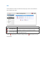
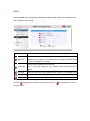
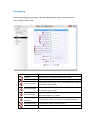
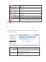
1
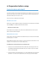
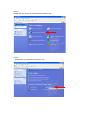
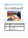
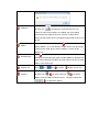
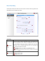
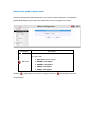
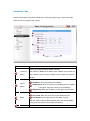
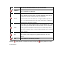
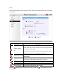
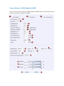
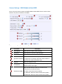
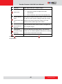
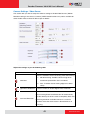
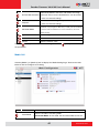
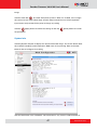
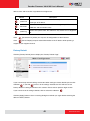
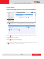
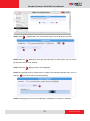
Encoder Firmware
A1D-310-V4.06.09-AC
User’s Manual
Table of Contents
1.
Recommended PC Specification
4
2.
Preparation before setup
5
Connect to device and setup IP ........................................................ 5
Sample screenshots to setup IP of your PC (Win XP) ...................... 7
3.
Configuring the IP device
11
Login ................................................................................................ 11
Live view .......................................................................................... 13
Host Section..................................................................................... 16
Host.............................................................................................. 16
Date & Time Setting ..................................................................... 17
Network Section.............................................................................. 18
Network link speed & duplex mode .............................................. 19
Connection Type .......................................................................... 20
IP Address Filtering ...................................................................... 22
DNS ............................................................................................. 24
DDNS ........................................................................................... 25
Port Mapping ................................................................................ 26
ToS ............................................................................................... 27
UPnPTM......................................................................................... 28
Video & Audio ................................................................................. 28
Basic ............................................................................................ 29
Advance ........................................................................................... 30
Advance - Motion Detection Settings ........................................... 31
Advance – Camera Settings......................................................... 32
Camera Settings - CMOS Models with WDR ............................... 33
Camera Settings - CMOS Models without WDR .......................... 37
Camera Settings - CCD Cameras ................................................ 40
Camera Settings - Video Server ................................................... 43
Media 1&2 .................................................................................... 44
Maintain........................................................................................... 46
User Account Setting ................................................................... 46
System Info .................................................................................. 47
Factory Default ............................................................................. 48
Firmware Upgrade ....................................................................... 49
Profile Pack .................................................................................. 50
Save & Reboot ............................................................................. 52
Logout .......................................................................................... 52
1. Recommended PC Specification
CPU
Core2Duo 2.13GHz and above
Memory
2 GB or above
Windows XP with SP2 or above. Windows Vista / Windows
Operating System
2003 / Windows 7
Internet Explorer 6.0 SP2 and above.
Video Resolution
SVGA or XGA with 1024x768 resolution
2. Preparation before setup
Connect to device and setup IP
Our IP device provides access through Internet Explorer. The IP address for your PC must be
within the same subnet as the IP device. You need to match the TCP/IP settings between PC
and IP device before you can access it via IE.
There are two ways to add devices to the network.
With DHCP server / router:
DHCP server assigns IP addresses to devices automatically. You can find them on the network
with our IP Utility. It is available on NVR CD and our website:
http://www.acti.com/IP_Utility
Run IP Utility to start auto device search. Click on the underlined IP links to access your IP
devices. You do not need to change IP.
Without DHCP server / router:
Please assign a static IP for each device and add them one by one. Connect to the first device
by following steps 1 to 5 below.
Before adding more devices into the network, you need to change the current device to a new
IP address so no two devices have IP conflict. (Steps 6 to 9).
For adding devices without DHCP, please see following steps.
1. Connect the PC to the Network Switch with the CAT5 cable, and change your PC’s IP to
192.168.0.99 / Subnet Mask 255.255.255.0 (101 is just a sample, it may be any number
from 1 to 254 except 100.)
2. Connect the device to your Network Switch. If it is a PoE enabled Switch, then the device is
powered on. If it is NOT a PoE enabled Switch, please also plug in the Power Adapter.
3. Open Internet Explorer (Version 6.0 or above) , and type in Default IP:
http://192.168.0.100
4. When you see the login window, please input default user and password:
Default Username: Admin
Password: 123456
5. After you log in, you will see the video from IP device. To go to the main menu, click the
“Setup” button on the top left.
6. Please go to Network -> Connection Type. Change the IP mode to Static and the IP
address to 192.168.0.101 or any other unused IP (Avoid 192.168.0.100, the IPs of your
PCs and other devices already in network.). Click “Apply” then click Maintain -> Save &
Reboot.
7. Internet Explorer will close after a few seconds. This is normal.
8. Wait for 30 seconds and open IE again by typing in the new IP. (In this example,
192.168.0.101). For later device you add into the network, please choose an IP that does
not is not used by any existing device.
9. If you have more than one device, continue again from step 2. Assign different new IP to
each camera (for instance -> 192.168.0.102, 192.168.0.103 …). You do not need to unplug
the existing devices from the switch because there is no IP conflict.
Sample screenshots to setup IP of your PC (Win XP)
The procedures below show how to setup your IP on Windows XP. If you use operating system
other than Windows XP, please refer to OS manuals for proper setup procedures.
STEP1
Start up your PC.
STEP2
Click the [Start] and select the "Control Panel"
STEP3
Double-click the "Network and Internet connections" icon.
STEP4
Double-click the "Network connections" icon
STEP5
Click “Local Area Connections”, and then click “Change settings of this connection” in the
Network Task menu.
STEP6
Click “Internet Protocol (TCP/IP)”, and then click [Properties]
STEP7
Click the “Use the following IP address” radio button and enter the IP address and the subnet
mask.
Please set the settings as below.
IP address: 192.168. 0.xxx
Subnet mask: 255.255.255. 0
(NOTE: xxx should be a number
from 1 to 254 except 100, which is
used by the IP device. Please also
make sure that no two equipments
use the same IP address in the
same network.)
STEP8
Click the [OK] button and the window dialog box will close.
3. Configuring the IP device
This section describes how to configure the IP device. The administrator has unlimited access
to all settings, while the normal user can only view live video. The IP device is configured under
a standard browser (Microsoft Internet Explorer 6.0 or above).
Login
STEP1
Open Internet Explorer 6.0 or above. You may download the latest version from:
http://www.microsoft.com/windows/ie/downloads/default.mspx
STEP2
Enter the IP address of the IP device and press enter to go to Login Page.
The default IP address is “192.168.0.100”
STEP3
Enter the Account name and the Password
(Default Account: Admin / Password: 123456).
STEP4
Select the language of the IP device user interface.
You can select between English, Traditional Chinese, Japanese, Spanish, Italian, German,
Portuguese, Greek, Russia, Turkey, Indonesia and Swedish. This user interface setting will
disappear once you log out, if you want to change the default user interface language, please
go to [Host] in the “Host & Date” section under the setup tab.
STEP5
Click the
button to login or click the
again. Once you’ve logged in, the “Live page” will be displayed as below.
button to re-enter
Live view
Click the
[Live] tab to show [Live page]. Refer to the table below for how to configure each
setting.
Function List
Function
Full Screen
Description
Click the icon
to stretch the preview to full screen. You can
click “Esc” button on the keyboard to return to previous display.
Snapshot
Click the icon “
” to take a snapshot. The snapshot picture
will be saved to the default folder
“C:\Users\”account name”\Picture”, in the format of
YYYYMMDD_HH_mm_ss.jpg.
Audio out
Click the icon
to enable the audio out from PC to IP
camera or video server. When it is enabled, your voice will be
transferred to the audio out of the IP camera or video server.
NOTE: you will need to have a microphone connected to your PC to
do that.
If dual stream mode is enabled, click
Media
to select which stream to
display (Media 1 or 2). The default is single stream only. To change
to dual stream mode, please refer to “Media 1” section under
“Setup” tab
Click
Encoder Type
to select the compression codec used in video
encoding. The Encoder type option includes MPEG-4, MJPEG and
H.264. Once selected, the video server/IP camera will start to send
video in new stream type.
Display size
Click
or
Audio in
Click the icon
of
to adjust
to mute or the icon
display screen size
to receive
audio in from the video server/IP camera. Drag the volume bar
to adjust the volume.
Digital Zoom
Digital zoom enables you to zoom into the image. You can
click
to zoom in and click
You can click the
to zoom out.
“no zoom” button to cancel
all zoom-in and go back to original status (no zoom status).
When you digitally zoom in the video, you can click
to pan/tilt the video up, down, left and right.
NOTE: This pan/tilt function does not work if the video is not
zoomed-in (no zoom status).
Indicates the network state. If the light on the right is
Network status
green, it means the network is ok. If the light is gray, it means
the network is broken.
The light on the left is not used
DO Setting
Click
Click
to set DO output level to High.
to set DO output level to Low. If your device
has more than one DO available, each DO is controlled
separately.
If you want to setup this IP camera/video server, please click the
“Setup Page” as displayed below.
[Setup] tab to switch to
Host Section
Click the
[Host] item on the “Setup Page”.
Host
Click the [Host] to enter Host settings page. Refer to the table below for how to configure each
setting.
Parameters
Host name
Description
Enter a host name, and this host name will be shown when you
use the IP utility or the SDK to search for the IP device.
Select the language of default user-interface. Each user login will
Language
see the default user-interface first.
Camera name The camera name is reserved for customer use.
Click the
[Apply] button to confirm the settings or click the
the parameters.
[Reset] button to re-enter
Date & Time Setting
Click the [Date & Time] item under Host & Date section to see Date & Time Page. Refer to the
table below for how to configure each setting.
Date Setting
Parameters
Description
Click this to enable IP device’s SNTP/NTP function. This enables this IP
device to synchronize its time settings with a SNTP/NTP server. You can
use this function to make sure all your IP devices’ time is the same.
SNTP/NTP
server
Additionally, with our embedded digital-time-code in the streaming, you
can tell the event sequence accurately.
IP address: Enter the IP address of the SNTP/NTP server.
Sync time: Select the time interval for this IP device to synchronize
its time.
Click this to manually setup the date & time.
Set manually
Date : Select the date
Time: Select the time
Time zone
Select the time zone offset for local settings
Select Type 1
Day Light
Saving
Click the
to specify daylight saving time by week number in a
month; select Type 2 to specify daylight saving time by date.
Start Time: Select the daylight savings start time.
End Time: Select the daylight savings end time.
[Apply] button to confirm the settings or click the
re-enter the parameters.
Network Section
Click the
[Network] item on the “Setup Page”.
[Reset] button to
Network link speed & duplex mode
Click the [Link Speed & Duplex Mode] item in the network section to display the “Link Speed &
Duplex Mode Setting Page”. Refer to the table below for how to configure each setting.
Parameters
Description
This item lets you select the network transmission speed. You
can select from
1. Auto detect (default setting)
WAN speed
2. 100Mbps / Full duplex
3. 100Mbps / Half duplex
4. 10Mbps / Full duplex
5. 10Mbps / Half duplex
Click the
[Apply] button to confirm the settings or click the
the parameters.
[Reset] button to re-enter
Connection Type
Click the [Connection Type] item to display the “Connection Type Page”. Refer to the table
below for how to configure each setting.
Parameters
Description
Click this to enable IP device’s DHCP function.
Dynamic IP
It will acquire its WAN port IP address from a DHCP server within the
address
same network. (You must have a DHCP server in order to enable this
function.)
Click this to manually enter the IP address.
Static IP
address
IP address: Enter the WAN port IP address.
Subnet mask: Enter the subnet mask of WAN port. If IP address
is changed, adjust the subnet mask accordingly.
ISP gateway: Enter the IP address of the gateway (the router).
Click this when you connect IP device directly to the xDSL modem.
User name: Enter the user name of your xDSL account.
PPPoE
Password: Enter the password of your xDSL account.
Note: You have to click the [Save Reboot] after you click the [Apply
button] to let this IP device start xDSL connections.
IPV6
Click the check box to support IPV6 protocol
Click the
[Apply] button to confirm the settings or click the
re-enter the parameters.
[Reset] button to
IP Address Filtering
WARNING: Please be very careful when using this function, as you may lose access
to your camera if you make mistakes in setup. You may either accidentally deny
yourself access, or forgot to include your own IP address in the allowed address list.
You will need to perform hard reset to be able to access the device again.
Click the [IP Address Filter] item to display the “IP Address Filtering Page”. Refer to the table
below for how to configure each setting.
Parameters
IP Address
Filter Enable
Description
Check this box to enable IP Address Filtering.
The filter can be set in either “Allow” mode or “Deny” mode.
1. “Allow” mode will refuse access to all IP addresses except the ones
Filter Type
listed below.
2. “Deny” mode will accept all incoming access except the IP addresses
listed below.
Make sure you include the Netmask in your consideration.
IP Address
The IP address you wish to allow or deny. Please note that the actual
range is modified by the Netmask.
Using Netmask allows you to set filtering for a whole range of IP address
at once, without the need to enter all of them individually. If you are not
Netmask
sure about the function of netmask, then you should use
255.255.255.255, and it will affect only a single IP address per line of
entry, or use 255.255.255.0 to use the same setting for all IP addresses
starting with the same three numbers. .
For each entry, you must check this box for it to be effective. For an entry
that you no longer need but does not wish to delete, you can uncheck it,
Enable
and the system will remember it for future use. If a new entry that has
never been used before does not have Enable checked, then it will not be
stored in memory.
Click this to use the current displayed info to do IP Address filtering. If you
Apply
setup correctly, it will change into a grayed out “Success” in a few
seconds.
Reset
Click the
Click this button to re-enter the parameters.
[Apply] button to confirm the settings or click the
the parameters.
[Reset] button to re-enter
DNS
Click the [DNS] item to display the “DNS Server Settings Page”. Refer to the table below for
how to configure each setting.
Parameters
Primary DNS server
Secondary DNS server
Click the
Description
Defines the IP address of the primary DNS server. This is used for
identifying this computer by name instead of IP address.
The IP address of the secondary DNS server. It will be used once
the primary DNS server fails.
[Apply] button to confirm the settings or click the
the parameters.
[Reset] button to re-enter
DDNS
Click the [DDNS] item to display the “DDNS Server Setting Page”. Refer to the table below for
how to configure each setting.
Parameters
Description
Click this to enable IP device’s DDNS function.
DDNS type
DDNS function enables user to connect to this IP device by domain name
even if its IP address is not static.
Click one of the DDNS service providers.
Service ISP
You can visit their website to get a DDNS service account for this IP
device.
Host name
Enter the host name of your DDNS service account. (ex: xxxx.dyndns.org)
User name
Enter the user name to login your DDNS service account.
Password
Enter the password to login your DDNS service account.
Click the
[Apply] button to confirm the settings or click the
the parameters.
[Reset] button to re-enter
Port Mapping
Click the [Port Mapping] item to display the “Port Mapping Page”. Refer to the table below for
how to configure each setting.
Parameters
Description
HTTP port
Select the port assigned for HTTP protocol access
HTTPS
Select the port assigned for HTTPS protocol access
Search server port1
Search server port2
Video control port
Video streaming port
(TCP Only)
Select the first port used by server search applications to detect
this IP device. (e.g. IP utlity)
Select the first port used by server search applications to detect
this IP device. (e.g. IP utlity)
Select the port used to support video control function by
application programs. (e.g. NVR)
Select the port used by this IP device for Video Streaming.
Video Multicast Port
Enable/disable multicast audio streaming
RTSP port
Select the port assigned for RTSP protocol access
RTP Multicast Video
Select the port for the multicast video streaming of media1 via
Port for Media1
RTP protocol
RTP Multicast Audio
Select the port for the multicast audio streaming of media1 via
Port for Media1
RTP protocol
RTP Multicast Video
Select the port for the multicast video streaming of media2 via
Port for Media2
RTP protocol
RTP Multicast Audio
Select the port for the multicast audio streaming of media2 via
Port for Media2
RTP protocol
Multicast IP
Select the multicast IP. Default settings is 228.5.6.1
Multicast TTL
Select the multicast TTL. Default setting is 255.
IGMP
Click the
Select video type connected to the video-in of this IP device. If
you use an incorrect video type, some images might be lost.
[Apply] button to confirm the settings or click the
[Reset] button to re-enter the
parameters.
ToS
Click the [ToS] (Type of Service) item to display the “ToS Page”. Refer to the table below for
how to configure each setting.
Parameters
TOS (type of
service)
TOS priority
Description
Select whether to add the TOS tag onto the streaming data.
Streaming data with a higher priority TOS tag will be transmitted
first when compared with other data.
Select the TOS tag’s priority to be added onto the streaming. You
can select between
1.Minimize-Delay
2.Maximize-throughout
3.Maximize-Reliability
4.Normal-Service
Click the
[Apply] button to confirm the settings or click the
[Reset] button to re-enter
the parameters.
UPnPTM
Click the [UPnPTM] item to display the “UPnPTM Setting Page”.
Click checkbox
to enable or disable the UPnPTM function. Edit the UPnP Friendly Name in
text field.
Click the [Apply] button
to confirm the settings or click the [Reset] button
parameters.
Video & Audio
Click the
[Video & Audio] item on the “Setup Page”.
to re-enter the
Basic
Click the [Basic] item to display the “Basic Page”. Refer to the table below for how to configure
each setting.
Parameters
Description
You can use this setting to limit the preview time in the Live
Maximum Stream
Time
Display Page. This function applies for user who logged in to this
IP device to view the video.
If the Maximum stream time is 0, this function will be disabled
and there’s no limit on Live Display page preview.
RTSP Authen Enable
RTP B2 Frame
Enable
Check box to enable RTP streaming’s Account/Password
authentication.
Check box to enable the B2 frame in RTP streaming
Audio
Select to enable or disable the audio function.
Input Sensitivity
Set audio input sensitivity to HIGH or LOW
Audio Out Volume
Select enable or disable the audio function.
Click the
[Apply] button to confirm the settings or click the
the parameters.
[Reset] button to re-enter
Advance
The “Advance” section includes motion detection settings and camera settings. The motion
detection settings section is the same across different cameras. The Camera settings section
differs between camera types. Here we describe the Motion Setup section. Click the [Advance]
item to see the “Advance Setting Page”.
Advance - Motion Detection Settings
STEP1: Click the Plus sign
to expand the Motion Detection settings then Click the
Motion Enable checkbox to enable motion detection.
STEP2: Click the
checkbox to enable motion detection for each individual region.
STEP3: Click one region to start to edit its size and location. You can click the “Adjust Column”
to drag motion region to your desired location. You can click the “Adjust Square” and drag to
adjust motion region size. You can click the upper right button to cancel this motion region.
Repeat above procedure to adjust the motion region.
STEP4: Set the
sensitivity of motion detection region.
STEP5: Set the
interval time of motion detection. After a motion event is triggered, no
more events will be triggered within this time in the same region
STEP6: Set the
trigger threshold of motion detection region. The larger this value, the
larger the object size needed to trigger motion detection.
STEP7: In motion activity
window, the bar shows the motion activity status. You can also
see the trigger threshold (Red line). When the motion activity exceeds the trigger threshold, the
bar would become red to indicate that a motion event has been triggered.
While viewing the motion activity window, you can adjust the motion sensitivity (the higher, the
easier camera considers video change to be an activity) and the threshold (the higher, the
larger the activity needed to trigger a motion event). If the default settings are not satisfactory
for your scene, you may try our alternative recommendations of:
Sensitivity: 80, Threshold: 2~5 (for normal environment)
Sensitivity: 80, Threshold: 5~10 (for very noisy environment)
Advance – Camera Settings
The lower half of the Advance page is the Camera Settings section. This portion of the screen
will differ between different devices. Different models will have different capabilities and
different settings available.
Please refer to this list and find the appropriate manual section for your device.
CMOS Models with WDR:
TCM-1231 / TCM-1232 / TCM-3401 / TCM-3411 / TCM-3511 / TCM-5211 / TCM-5212 /
TCM-5601 / TCM-5611 / TCM-7411
CMOS Models without WDR:
TCM-4301 / TCM-4101
CCD Models
TCM-5311 / TCM-5312
Video Servers
TCD-2500 / TCD-2100
Camera Settings - CMOS Models with WDR
Here is the user interface section for CMOS models with WDR function. Please note that some
functions may not be available to all models.
Adjust the settings as per the following table
Parameters
Description
Video Flipping
Check this box to flip the video up-down
Video Mirror
Check this box to mirror the video left-right
Lens Compensation
Check this box to use best pre-set settings for bundled lens
Line frequency
Sharpness
Change settings between 60Hz or 50Hz, depending on the
AC power type of your region.
Select the sharpness value
Select the day/night mode.
Auto: The camera would switch between day and night mode
Day/Night mode
automatically. It will follow the Day Gain and Night Gain
threshold defined by user below.
Day: The camera will stay in day (color) mode.
Night: The camera will stay in night (black & white) mode.
Some models have more than one method of measuring
lighting level to decide between Day / Night Mode. Choose
Day/Night Type
between CdS Sensor and DSP Image processor if the model
allows for both. If there is only one type of mechanism
available, then this setting cannot be changed.
This value controls the level of light where camera switches
Day Gain Threshold
into Day mode. Increasing it will make camera switch to night
mode at a darker illumination level.
This value controls the level of light where camera switches
Night Gain Threshold into night mode. Increasing it will make camera switch to
night mode at a darker illumination level.
This setting controls whether IR LED will turn on at night. If it
Day/Night IR LED
is Auto, the IR LED will turn on and off when switching
between day mode and Night Mode. Choosing Disable will
keep the IR LED off during night mode.
This setting controls whether IR Cut Filter will be removed at
Day/Night IR Cut
night. If it is Auto, the IR LED will turn on and off when
switching between day mode and Night Mode. Choosing
Disable will keep the IR LED off during night mode.
This setting is the delay between lighting level change and
actually switching to day mode, described in seconds. This is
Day Trigger Interval
because in actual scenes, there may be brief periods of light
in night time, such as a headlight from approaching car. This
prevents from unnecessary Day/Night changes.
This setting is the delay between lighting level change and
actually switching to night mode, described in seconds. This
Night Trigger Interval
is because in actual scenes, there may be brief periods of
darkness during daytime. This may be caused by passing
clouds or temporary blocks before the camera. This prevents
from unnecessary Day/Night changes.
This setting determines whether to use the WDR function or
not. Select disable to stop using WDR image processing.
WDR Status
Select Default to enable WDR with the default level of 120,
which provides moderate image enhancement. Select
manual to change the WDR level yourself and see what is the
best value for your scenario.
This option will only appear if WDR Status is set to “Manual”.
The higher the value, the more strongly the camera tries to
Level
balance the light and dark areas. The lower the value, the
more closely the image resembles the raw video. Try and see
what value suits your scene best.
Select the white balance mode. You need to wait for
5~10seconds to see the final result.
1. AUTO : Auto white balance (default)
2. INDOOR1: Select the indoor white balance profile 1.
3. INDOOR2: Select the indoor white balance profile 2.
4. OUTDOOR1: Select the outdoor white balance profile 1.
5. OUTDOOR2: Select the outdoor white balance profile 2
White Balance Mode
6. HOLD CURRENT: Select this to let the IP camera
automatically obtain a best white balance setting
according to current environment. The IP camera will
use this setting to adjust color.
NOTE: This setting will be lost after you reboot the
camera.
7. MANUAL: Select this to enable manual setting of the
white balance. You will need to enter the R Gain and B
gain setting below.
R Gain
Add or decrease redness to the video when under Manual
(Manual White
White Balance mode. (This function is only available in
balance mode only)
Manual White balance mode.)
B Gain
Add or decrease blueness to the video when under Manual
(Manual White
White Balance mode. (This function is only available in
balance mode only)
Manual White balance mode.)
Select exposure mode to auto or manual.
1. Auto: The IP camera will adjust the exposure
Exposure mode
automatically.
2. Manual: (In Manual White balance mode only)
Manually select the Exposure Gain and Shutter
Speed below.
AGC Gain
(In auto Exposure
mode only)
Exposure Gain (In
Manual Exposure
Mode only)
Auto Gain Control value determines how much should the
signal be amplified. The higher AGC Gain value, the brighter
the image. In dark scenes, lower AGC Gain will reduce noise
level.
Select the exposure Gain of the IP camera. The higher the
value = brighter images.
Shutter Speed (In
Increase or decrease the shutter speed. The closer the
Manual Exposure
number is to 1, the better nighttime performance is, although
Mode only)
this also causes motion blur to the video.
Flickless Mode
Enable the flickless or disable the flickless mode.
Maximum Auto
Shutter Speed
(In auto Exposure
mode only)
In auto exposure mode, IP camera will slow down the shutter
to increase exposure time under low light. This controls the
maximum amount of exposure time. Lengthen the time to
allow for sharper image at night, shorten to reduce motion
blur.
Brightness
Select the brightness value
Saturation
Select the saturation value
Contrast
Select the contrast value
Click the
[Apply] button to confirm the settings or click the
the parameters.
[Reset] button to re-enter
Camera Settings - CMOS Models without WDR
Here is the user interface section for CMOS models without WDR. Please note that some
functions may not be available to all models.
Adjust the settings as per the following table
Parameters
Description
Video Flipping
Check this box to flip the video up-down
Video Mirror
Check this box to mirror the video left-right
Lens Compensation
Check this box to use best pre-set settings for bundled lens
This value controls the level of light where camera switches
Night Gain Threshold into night mode. Increasing it will make camera switch to
night mode at a darker illumination level.
Sharpness
Line frequency
Select the sharpness value
Change settings between 60Hz or 50Hz, depending on the
AC power type of your region.
Select the white balance mode. You need to wait for
5~10seconds to see the final result.
White Balance Mode
8. AUTO : Auto white balance (default)
9. INDOOR1: Select the indoor white balance profile 1.
10. INDOOR2: Select the indoor white balance profile 2.
11. OUTDOOR1: Select the outdoor white balance profile 1.
12. OUTDOOR2: Select the outdoor white balance profile 2
13. HOLD CURRENT: Select this to let the IP camera
automatically obtain a best white balance setting
according to current environment. The IP camera will
use this setting to adjust color.
NOTE: This setting will be lost after you reboot the
camera.
14. MANUAL: Select this to enable manual setting of the
white balance. You will need to enter the R Gain and B
gain setting below.
R Gain
Add or decrease redness to the video when under Manual
(Manual White
White Balance mode. (This function is only available in
balance mode only)
Manual White balance mode.)
B Gain
Add or decrease blueness to the video when under Manual
(Manual White
White Balance mode. (This function is only available in
balance mode only)
Manual White balance mode.)
Select exposure mode to auto or manual.
3. Auto: The IP camera will adjust the exposure
Exposure mode
automatically.
4. Manual: (In Manual White balance mode only)
Manually select the Exposure Gain and Shutter
Speed below.
AGC Gain
(In auto Exposure
mode only)
Exposure Gain (In
Manual Exposure
Mode only)
Auto Gain Control value determines how much should the
signal be amplified. The higher AGC Gain value, the brighter
the image. In dark scenes, lower AGC Gain will reduce noise
level.
Select the exposure Gain of the IP camera. The higher the
value = brighter images.
Shutter Speed (In
Increase or decrease the shutter speed. The closer the
Manual Exposure
number is to 1, the better nighttime performance is, although
Mode only)
this also causes motion blur to the video.
Flickless Mode
Enable the flickerless or disable the flickerless mode.
Maximum Auto
In auto exposure mode, IP camera will slow down the shutter
Shutter Speed
to increase exposure time under low light. This controls the
(In auto Exposure
maximum amount of exposure time. Lengthen the time to
mode only)
allow for sharper image at night, shorten to reduce motion
blur.
Brightness
Select the brightness value
Saturation
Select the saturation value
Contrast
Select the contrast value
Click the
[Apply] button to confirm the settings or click the
the parameters.
[Reset] button to re-enter
Camera Settings - CCD Cameras
Here is the user interface section for CCD models.
Adjust the settings as per the following table
Parameters
Description
Mirror Mode
Check this box to flip the video up-down
Flip Mode
Check this box to mirror the video left-right
Select the white balance mode. After you set the parameter,
you need to wait for 5~10seconds to see the final result.
1. AUTO : Auto white balance (default)
2. INDOOR1: Select the indoor white balance profile 1.
3. INDOOR2: Select the indoor white balance profile 2.
4. OUTDOOR1: Select the outdoor white balance
White Balance Mode
profile 1.
5. OUTDOOR2: Select the outdoor white balance
profile 2
6. HOLD CURRENT: Select this to let the IP camera
automatically obtain a best white balance setting
according to current environment. The IP camera will
use this setting to adjust color.
Encoder Firmware V4.06.09 User’s Manual
NOTE: This setting will be lost after you
reboot the camera.
7. MANUAL: Select this to enable manual setting of the
white balance. You will need to enter the R Gain and
B Gain setting below.
R Gain
Add or decrease redness to the video when under Manual
(Manual White
White Balance mode. (This function is only available in
balance mode only)
Manual White balance mode.)
B Gain
Add or decrease blueness to the video when under Manual
(Manual White
White Balance mode. (This function is only available in
balance mode only)
Manual White balance mode.)
Select the day/night mode.
Auto: The camera would switch between day and night mode
Day/Night mode
automatically. It will follow the Day Gain and Night Gain
threshold defined by user below.
Day: The camera will stay in day (color) mode.
Night: The camera will stay in night (black & white) mode.
This value controls the level of light where camera switches
Day Gain Threshold
into day mode. Increasing it will make camera switch to day
mode at a darker illumination level.
This value controls the level of light where camera switches
Night Gain Threshold into night mode. Increasing it will make camera switch to night
mode at a darker illumination level.
Line Frequency
BLC Mode
Change settings between 60Hz or 50Hz, depending on the
AC power type of your region..
Enable or disable the back light compensation mode.
Select exposure mode to auto or manual.
1. Auto: The IP camera will adjust the exposure
Exposure mode
automatically.
2. Manual: (In Manual White balance mode only)
Manually select the Exposure Gain and Shutter
Speed below..
Flickless Mode
Enable the flickless or disable the flickerless mode
Select DC IRIS mode to auto or off.
DC-Iris
mode
1. Auto: The IP camera will adjust the Iris automatically.
2. Off: The iris is fixed.
AGC Gain
When exposure mode is auto, IP camera will adjust its shutter
(In auto Exposure
speed according to AGC gain and the Maximum auto shutter
41
www.acti.com
Encoder Firmware V4.06.09 User’s Manual
mode only)
speed. Higher AGC gain = brighter images.
Select exposure mode to auto or manual.
Shutter mode
1. Auto: The IP camera will adjust the shutter
automatically.
2. Manual: Manually select the Shutter Speed below.
Maximum Shutter
When exposure mode and shutter mode are auto, IP camera
Speed
will adjust its shutter speed according to AGC gain and the
(In auto shutter mode Maximum auto shutter speed. This setting is to set the
maximum shutter speed range of this camera.
only)
Exposure Gain (In
Manual Exposure
Mode only)
Select the exposure Gain of the IP camera. The higher the
value = brighter images.
Shutter Speed
Increase or decrease the shutter speed. The closer the
(In manually shutter
number is to 1, the better nighttime performance is, although
mode only)
this also causes motion blur to the video.
Brightness
Select the brightness value
Click the
[Apply] button to confirm the settings or click the
[Reset] button to re-enter
the parameters.
42
www.acti.com
Encoder Firmware V4.06.09 User’s Manual
Camera Settings - Video Server
This section tells you how to setup the Advance settings of H.264 Video Servers. (Motion
Detection setting is the same as cameras). WDR related functions may not be available for
some models. Please check IP device spec for details.
Adjust the settings as per the following table
Parameters
Description
Select the method used for calculating video deinterlacing
1. 3D deinterlacing: Provides clearer image when
Deinterlace
movement speed within view is moderate
2. Intra : Provides clearer moving edge but at lower
clarity.
Digital Noise Reduction Choose to enable or disable Digital Noise Reduction
Choose to turn Black Level Extension on, off or use
manual setting. Black Level Extension will automatically
Black Level Extension
shift the darkest part of the scene to completely dark, thus
increasing maximum available contrast. It is useful in
situations where the whole scene is blurred white as in
heavy fog.
43
www.acti.com
Encoder Firmware V4.06.09 User’s Manual
Automatically detects skin color, and softens the image
Skin Tone Enhancement around skin area to cover skin blemishes. Can be turned
on, off or use manual settings.
Use this to enhance image sharpness. User may turn this
Sharpness
on, off or use manual settings.
Modulates overly bright or dark areas, so that you can see detail
WDR Color Mode
at extreme ends of illumination. Can be turned on, off or use
manual settings.
Brightness
Select the brightness value
Saturation
Select the saturation value
Contrast
Select the contrast value
Click the
[Apply] button to confirm the settings or click the
[Reset] button to re-enter
the parameters.
Media 1&2
Click the [Media 1] or [Media 2] item to display the “Media Setting Page”. Refer to the table
below for how to configure each setting.
Parameters
Stream Mode
Description
Select the encoder’s streaming mode.
Dual Stream Mode: In this mode, the IP camera/video server can
44
www.acti.com
Encoder Firmware V4.06.09 User’s Manual
send two types of streams with different configurations, including
resolution, frame rate, compression type and bit rate. You can setup
each stream in [Media 1] and [Media 2].
Single Stream Mode: In this mode, the IP camera/video server will
send streams with the same configuration including resolution, frame
rate, compression and bit rate.
Encoder Type
Resolution
Frame rate
Select the encoder’s compression type.
MPEG-4 / MJPEG / H.264
Select the video resolution of the IP device.
Select the frame rate by clicking and dragging the red stick. Click
[Apply] to update and see the new frame rate.
Select the video bit rate mode.
Constant Bit Rate: The video bit rate remains constant at all
Video Bit Rate
conditions.
Variable Bit Rate: The video bit rate will vary based upon scene
Mode
complexity and amount of movement. The quality will remain the
same.
This puts a hard cap on the maximum bit rate allowed in any given
Video Max
second of video streaming. Assigning a limited bit rate may result in
Bitrate
a few dropped frames rate when the stream data overflows the
allowed bit rate. Doing so will also disable Bit Rate setting below.
Select the bit rate of the video streaming. You can select from
28Kbps to 6Mbps.
Bitrate
Note: Lower bit rate consumes less bandwidth but delivers lower
quality images.
High bit rate consumes more bandwidth but delivers higher
quality images.
1.
When encoder type is MJPEG:
Select the quality value of MJPEG encoder type from 1 to 100.
Quality
2.
When encoder type is MPEG4 or H.264, and video bitrate mode
is “Variable Bit Rate”
Select the quality value from
High / Middle / Low
Click the
[Apply] button to confirm the settings or click the
[Reset] button to re-enter
the parameters.
45
www.acti.com
Encoder Firmware V4.06.09 User’s Manual
Maintain
Click the
[Maintain] item on the “Setup Page”.
User Account Setting
Click the [User Account Setting] item to display the “User Account Setting Page”.
Setup the account names and their respective passwords. There are 1 root (administrator)
account and 10 common user accounts
. Administrator account allows the user to watch
the live view and setup everything; but common user account allows user only to watch the live
46
www.acti.com
Encoder Firmware V4.06.09 User’s Manual
image.
Click the check box
to enable “Anonymous preview”. When it is enabled, user can login
this camera to view video without input account and password. But user will be required to
input account and password if they want to change any setting
Click the
[Apply] button to confirm the settings or click the
[Reset] button to re-enter
the parameters.
System Info
Click the [System Info] item to display the “System Information Page”. This shows details about
this IP device including system information, WAN status and system log. Refer to the table
below for how to configure each setting.
View the information at the 3 textboxes. This information is very useful to understand the IP
47
www.acti.com
Encoder Firmware V4.06.09 User’s Manual
device status and to resolve any problem that might occur.
Column
System info
WAN status
System log
Description
It shows the firmware version, MAC address, production ID, and factory
default type of IP device.
It shows the WAN port’s IP address, netmask, gateway, DNS server,
DDNS host and connection status.
It shows the system event. This column is very useful to as a diagnostic
tool.
Click
[Parameter List] where you may see all configurations of the IP device.
Click
[Server Report] to export related information of the IP device while reporting a
support to your support channel.
Factory Default
Click the [Factory Default] item to display the “Factory Default Page”.
If you want to keep network settings and restore other settings to factory default, please click
radio box
. If you click
instead , all the settings would be lost. You will have to use
factory default IP setting to connect to this camera. Please refer to previous login section.
If you want to reset all setting to default, click to select this radio box
.
Click the [Apply] button to show a warning dialog that reminds you again before restoring the
device to factory default.
48
www.acti.com
Encoder Firmware V4.06.09 User’s Manual
Firmware Upgrade
Click the [Firmware Upgrade] item to display the “Firmware Upgrade Page”. Upgrade the IP
device’s firmware through this page with the following instructions.
Click
Click the
[Apply] button. The ‘’Firmware Upgrade Page-2” will be displayed as below.
[Browse] to select the upgrade image file and click the [enter]. You can always
get the latest version at our website.
Click the
[Apply] button to start upgrading
The upgrade process window will show a progress bar indicating upgrade status. You can click
the
[Cancel] button to stop the firmware upgrade.
49
www.acti.com
Encoder Firmware V4.06.09 User’s Manual
Once the process is finished, the progress bar will show the upgrading as OK, and reboot the
IP device system.
NOTE: If you cancel the firmware upgrade during upgrade process, the browser
window will be closed
Profile Pack
Profiles are sets of parameters that control how the image sensor behaves. Sometimes profiles
are fine-tuned again to suit a specific environment, or for generally better image. They are not
updated as frequently as firmware, and a good profile can stay in use for a very long time.
Occasionally, you may wish to load a new profile pack into your camera. This section tells you
how to upgrade IP Camera’s Profile Pack.
Click the [Profile pack] item to display the “Profile Pack Page”.
50
www.acti.com
Encoder Firmware V4.06.09 User’s Manual
STEP1: Click
[Apply] button. The ‘’Profile Pack Page-2” will be displayed as below.
STEP2: Click the
[Browse] to select the new profile pack and click [enter]. You can always
get the latest version at our website.
STEP3: Click the
[Apply] button to start upgrading
STEP5: The upgrade process window shows a progress bar indicating upgrade status. You can
click the
[Cancel] to stop the firmware upgrade.
STEP6: The progress bar shows the upgrading is completed, and system is rebooting.
51
www.acti.com
Encoder Firmware V4.06.09 User’s Manual
Save & Reboot
This section tells you how to save all the settings and reboot this IP device. This is critical
because some settings might not take effect before save and reboot. Click the [Save & Reboot]
item to display the “Reboot Page”.
The Action LED indicator will go dark to indicate that the IP device is rebooting. After around 30
seconds, the Action LED will light up again to indicate that the reboot is completed.
Logout
Clicking this item allows you to log out of the IP device. Be sure to logout this IP device once
your setting is completed.
52
www.acti.com