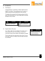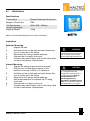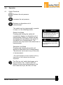
1
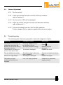
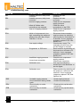
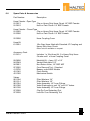
High Pressure Digital Inflation Equipment
HIGH PRESSURE
DIGITAL TYRE INFLATOR
WARNING
by trained personnel.
This equipment must only be used
anual before use.
Read and understand Operation M
89XHA
HIGH PRESSURE
DIGITAL TYRE INFLATOR
89XHB
S P E C I F I C A T I O N S
I N S T A L L A T I O N
O P E R A T I O N
S E R V I C E
Please read this
manual before carrying
out any installation or
service procedures.
Upon Installation pass
this manual to the
equipment owner.
1
www.haltec.com
Contents
1.0
Introduction
This Manual
Digital Inflation Overview
General Specifications
2.0
89XHA Model
Specifications
Installation
3.0
89XHB Model
Specifications
Installation
4.0
Operations
Switch Functions
Inflation & Deflation (Single Display)
Volume Adjustment
5.0
Troubleshooting
6.0
Spare Parts & Accessories
7.0
Wiring Diagram
8.0
Component Replacement
9.0
Compressed Air Systems
10.0
Warranty
11.0
Initial Verification Certificate
12.0
Glossary & Conversions
2
www.haltec.com
1.0
Introduction
1.1
This Manual
Congratulations on selecting a Haltec High Pressure
Digital Tire Inflator. This equipment has a number of
unique features that are explained in this manual.
Throughout the manual the following symbols will be
used, this information is for your safety and to prevent
damage to this product.
!
CAUTION
The hazard or unsafe practice
could result in minor injury
1.2
!
WARNING
The hazard or unsafe practice
could result in severe injury or
death.
Digital Inflation Overview
Your Haltec High Pressure Digital Tire Inflator has a
dual pneumatic valve controlled by an electronic
circuit that controls the inflation and deflation process.
!
WARNING
To avoid the risk of electrical
shock, personal injury or death
disconnect power before
servicing this equipment.
The process will only commence when there is more
than 3psi, 20 kPa or 0.2bar in the tire when the hose
is connected.
3
www.haltec.com
1.3
!
Relative Humidity
100%
Supply Voltage
11-18Vdc, 8-16Vac
100-120V 50/60Hz
220-240V 50/60Hz
Current
1A Max
Fuse
Auto Reset
1.1A Nominal
Max Inlet Air Supply
220psi, 1500 kPa,
15.0 bar
Recommended Inlet
Air Supply
10 psi, 70kPa or
0.7 bar above the
maximum set pressure
of the unit.
CAUTION
To avoid equipment damage,
never exceed the manufactures
maximum inlet pressure of 220
psi, 1500 kPa or 15.0 bar.
!
0oC to + 60oC (without heater)
32oF to 140oF
-20oC to + 60oC (with heater)
-4oF to 140oF
WARNING
This equipment is not intended
for use by children without adult
supervision.
!
Operating Temperature
WARNING
To avoid the risk of personal
injury, especially to the eyes, face
or skin DO NOT direct the air
stream at any person/s.
!
General Specifications
CAUTION
This equipment has NO user
serviceable parts. Only trained,
experienced repair personnel
employed by an authorised
service agent should perform
service to this equipment.
Operating Pressure
Maximum
Minimum
181 psi, 1250 kPa,
12.5 bar
5 psi, 35 kPa, 0.3 bar
Accuracy
Up to 0.5% FS
Display Increments
1 psi, 5 kPa, 0.1 bar
Units of Measurement
psi, kPa, bar, kg/cm2
Default to Safe Setting
1 minute
(DTSS) Reset Time
(Retail Petroleum Equipment ONLY)
4
www.haltec.com
2.0
89XHA Model
Specifications
Construction
Diecast Aluminium Enclosure
Degree of Protection
Unit Dimensions
IP66
HIGH PRESSURE
DIGITAL TYRE INFLATOR
WARNING
y trained per onnel.
y be sed bs
This equipment must onlu
anual before use.
Read and understand Operation M
269 x 285 x 106mm
(excluding packaging)
Shipping Weight
5.4kg
89XHA
Refer to General Specifications for further information.
Installation
External Mounting
1.
Unpack the unit.
2.
Hold the unit up on the wall and mark where the
four (4) holes are to be drilled.
3.
Secure the unit using suitable fasteners.
4.
Connect the air supply to the unit.
5.
Connect the power supply, refer to the rating label
for the correct power requirements.
Internal Mounting
1.
Unpack the unit and remove the front panel
2.
Drill the four (4) Mounting locations in the
backbox to suit up to M6 or 1/4” fasteners.
3.
Hold the unit up on the wall and mark where the
four (4) holes are to be drilled.
4.
Secure the unit using suitable fasteners.
5.
Seal these fasteners to maintain the IP rating
of the unit.
6.
Connect the air supply to the unit.
7.
Connect the power supply, refer to the rating label
for the correct power requirements.
!
WARNING
Ensure that the product is
connected to the correct power
and air supply, refer to rating
label and general specifications.
!
CAUTION
If this equipment is being installed
on a retail petroleum site
consideration must be given to
the requirements of German
Standard DIN EN 837-1
(Druckmeßgeräte mit
Rohrfedern), Ausgabe Februar
1997) or the relevant Hazardous
Area standard for your region.
5
www.haltec.com
3.0
HIGH PRESSURE
DIGITAL TYRE INFLATOR
89XHB Model
Specifications
Construction
Degree of Protection
Unit Dimensions
Diecast Aluminium Enclosure
IP66
269 x 285 x 106mm
(excluding packaging)
Shipping Weight
89XHB
4.1kg
Refer to General Specifications for further information.
Installation
!
WARNING
Ensure that the product is
connected to the correct power
and air supply, refer to rating
label and general specifications.
!
CAUTION
If this equipment is being installed
on a retail petroleum site
consideration must be given to
the requirements of German
Standard DIN EN 837-1
(Druckmeßgeräte mit
Rohrfedern), Ausgabe Februar
1997) or the relevant Hazardous
Area standard for your region.
External Mounting
1.
Unpack the unit.
2.
Hold the unit up on the wall and mark where the
four (4) holes are to be drilled.
3.
Secure the unit using suitable fasteners.
4.
Connect the air supply to the unit.
5.
Connect the power supply, refer to the rating label
for the correct power requirements.
Internal Mounting
1.
Unpack the unit and remove the front panel
2.
Drill the four (4) Mounting locations in the
backbox to suit up to M6 or 1/4” fasteners.
3.
Hold the unit up on the wall and mark where the
four (4) holes are to be drilled.
4.
Secure the unit using suitable fasteners.
5.
Seal these fasteners to maintain the IP rating
of the unit.
6.
Connect the air supply to the unit.
7.
Connect the power supply, refer to the rating label
for the correct power requirements.
6
www.haltec.com
4.0
Operation
4.1
Switch Functions
Reduces the set pressure.
Increases the set pressure.
Displays an alternative unit of
measurement.*
This switch can be programmed to operate
in one (1) of the following modes:
Default Unit Mode
Pressing and holding the switch will
momentarily display an alternative unit of
measurement. When you release the key
the display will immediately revert back to
the default unit of measurement. The
pressure can only be set in the default unit of
measurement.
!
WARNING
To avoid the risk of personal
injury, especially to the eyes, face
or skin DO NOT direct the air
stream at any person/s.
!
WARNING
This equipment is not intended
for use by children without adult
supervision.
Selectable Unit Mode
Pressing and releasing the switch will
display an alternative unit of measurement.
The pressure can be set in any of the units
of measurement.
* The units displayed on each machine will vary
depending on the software that has been
requested.
The ‘Flat tire only’ switch discharges up to
five (5) bursts of air. Used to start the
inflation process when the pressure in the
tire is less than 3 psi, 20 kPa or 0.2 bar.
7
www.haltec.com
4.2
!
4.2.1
Set the desired pressure, refer to Section 4.1
for the function of each switch.
4.2.2
Connect the hose to the tire, ensure the hose
is connected securely. Air leaks will cause an
error message to be displayed, refer to
Section 5.0.
4.2.3
The pressure in the tire will be displayed.
4.2.4
The unit will inflate or deflate the tire to the set
pressure. Periodically the process will stop
and display the pressure in the tire.
4.2.5
If the pressure in the tire is less than 3 psi, 20
kPa or 0.2 bar the process will not commence
until the ‘Flat tire only’ switch is pressed, refer
Section 4.1.
4.2.6
The scroll bar will indicate that the unit is
inflating or deflating, see below.
4.2.7
When the set pressure is reached the display
will flash and the unit will beep five (5) times.
This will continue until the hose is
disconnected, during this time the keypad will
be disabled.
WARNING
Ensure that the product is
connected to the correct power
and air supply, refer to rating
label and general specifications.
!
Inflation & Deflation
CAUTION
If this equipment is being installed
on a retail petroleum site
consideration must be given to
the requirements of German
Standard DIN EN 837-1
(Druckmeßgeräte mit
Rohrfedern), Ausgabe Februar
1997) or the relevant Hazardous
Area standard for your region.
8
www.haltec.com
4.3
Volume Adjustment
4.3.1 Turn the unit off.
4.3.2 Press and hold the decrease and ‘Flat Tire Only’ switches,
refer to Section 4.1.
4.3.3 Turn the unit on, VOL will be displayed.
4.3.4 Adjust the volume using the increase and decrease switches,
refer to Section 4.1.
4.3.5 To store the setting press the ‘Flat Tire Only’ switches.
Further changes can be made by repeating the above procedure.
5.0
Troubleshooting
The following chart has been prepared to assist with diagnosis of faults.
PROBLEM
No display.
The inflation process does not
commence, even when the
pressure is set and the hose is
connected to the tire.
The display will not move or is
stuck on a particular value.
POSSIBLE CAUSE
No power supply.
The tire is deflated below 3
psi, 20 kPa or 0.2 bar.
The hose connector is faulty.
The switch is damaged.
Replace the hose
connector.
Replace the switch.
The unit deflates very slowly.
The silencer plug on the valve
block is blocked.
The beeper is damaged.
Remove and clean the silencer
plug.
Replace the beeper.
Low or nil supply pressure.
Check the air compressor
supply pressure.
The unit no longer beeps.
The inflation process
commences but does not
complete.
SOLUTION
Check power supply.
Press
9
www.haltec.com
5.0
Troubleshooting, cont.
PROBLEM
ER1
ER2
ER3
POSSIBLE CAUSE
Unstable pressure, faulty hose
connector.
Unstable pressure, faulty hose
connector.
Incorrect supply pressure.
Inflate & Deflate valve
connections are reversed.
Low or nil supply pressure.
ER4
Initial or final pressure is too
high, exceeding the maximum
pressure by more than 20 psi,
140 kPa or 1.4 bar.
ER5
Low supply voltage.
ER6
Programme or PCB error.
ER7
Insufficient supply pressure
Loose hose connection
SOLUTION
Replace the hose
connector.
Replace the hose
connector.
Check the air compressor
supply pressure.
Check the valve
connections on the PCB.
Check the air compressor
supply pressure.
Disconnect hose connector,
reset processor by switching
off the power for a minimum of
5 seconds. If error message
reappears replace PCB, refer
Section 8.0.
Check power supply. The
message will clear when the
correct voltage is restored.
Reset machine by switching off
the power for a minimum of 5
seconds. If error message
reappears replace PCB, refer
Section 8.0.
Check the air compressor
supply pressure
Check hose connection.
ER8
Calibration error.
Unit requires calibration,
contact your local distributor or
service agent.
ER9
Calibration error.
Reset machine by switching off
the power for a minimum of 5
seconds. If error message
reappears replace PCB, refer
Section 8.0.
ERP
ERU
ERB
Unstable supply pressure
Hose connection during inflate
Ccycle.
Short circuitry on valve
cconnection
Check supply pressure.
Check hose connection.
Check and dry up the valve
cconnection
Short circuitry on buzzer
cconnection
Check and dry up the buzzer
cconnection
10
www.haltec.com
6.0
Spare Parts & Accessories
Part Number
Description
Hose Chucks - Open Type
91.0213
Clip on Heavy Duty Hose Chuck 1/4” BSP Female
91.0210
Hold on Twin Chuck 1/4” BSP Female
Hose Chucks - Closed Type
91.5055
Clip on Heavy Duty Hose Chuck 1/4” BSP Female
91.5056
Hold on Twin Chuck 1/4” BSP Female
22.0000
Hose Kit
61.0001
Hose Coupling Cover
10m Grey Hose fitted with Standard JP Coupling and
Heavy Duty Hose Chuck
Other colours available on request
Accessory Pack
61.0101
Includes 1 x 10m Hose Kit, 2 x Heavy Duty Hose
Chucks and 1 x Hose Coupling Cover
93.0800
94.5049
94.0951
97.5052
41.0702
45.1042
45.1050
Manifold Kit - 4 way 1/2” x 1/4”
Vented Slide Valve 1/2”
Non Return Valve, 1/4” BSP M/F
Core Removal Tool - Standard
Beeper, suits 89XD Models
Piezo Switch
Mechanical Switch
Valves
95.1004
95.1514
96.1024
95.1026
96.1038
97.5058
97.5258
Filter Washers 1/4”
Filter Washers 1/2”
Valve Assembly 1/4” Less Fittings
Valve Diaphragm to suit 1/4” and 1/2” Valves
Valve Assembly 1/2” Less Fittings
Clip-On Core Retracting Tool
Lock-On Core Retracting Tool
11
www.haltec.com
7.0
Wiring Diagram
!
WARNING
Ensure that the product is
connected to the correct power
and air supply, refer to rating
label and general specifications.
!
CAUTION
If this equipment is being installed
on a retail petroleum site
consideration must be given to
the requirements of German
Standard DIN EN 837-1
(Druckmeßgeräte mit
Rohrfedern), Ausgabe Februar
1997) or the relevant Hazardous
Area standard for your region.
12
www.haltec.com
8.0
Component Replacement
8.1
PCB
8.1.1 To remove the existing PCB, open the
unit.
8.1.2 Disconnect the switches from the
connector.
8.1.3 Unplug all other connections on the PCB.
8.1.4 Remove the sample tube from the valve
block.
8.1.5 Remove the 4 screws that retain the
PCB.
8.1.6 To install the replacement PCB remove
the clear protective film over the LCD.
8.1.7 Connect the sample tube to the valve
block.
8.1.8 Replace the 4 screws that retain the PCB
in position.
8.1.9 Reconnect the switch connector
and all other connections.
!
WARNING
To avoid the risk of electrical
shock, personal injury or death
disconnect power before
servicing this equipment.
13
www.haltec.com
9.0
Compressed Air Systems
The information in this section is designed to provide
some basic information about compressed air
systems and the use of electronic inflation
equipment.
Compressed air systems contain oil and water, it is
important to filter and drain these from the system.
The water is generated by condensation and oil can
be carried into the line from the compressor. A basic
system is illustrated below. The components of this
system are as follows:
1.
2.
3.
4.
5.
6.
Air Compressor
Air Receiver Tank
Valves
Filter & Regulator
Condensate Drain (Water Tap)
Electronic Tire Inflator
!
To avoid the risk of personal
injury, especially to the eyes, face
or skin DO NOT direct the air
stream at any person/s.
!
WARNING
This equipment is not intended
for use by children without adult
supervision.
1-2
o
!
3
WARNING
CAUTION
To avoid equipment damage,
never exceed the manufacturers
maximum inlet pressure of 150
psi, 1035 kPa or 10.3 bar.
6
2
4
!
1
5
3
3
5
3
CAUTION
This equipment has NO user
serviceable parts. Only trained,
experienced repair personnel
employed by an authorised
service agent should perform
service to this equipment.
14
www.haltec.com
Each system and installation of electronic inflation
equipment is different. However it is imperative with
any system that the drain valves (No. 3) are opened
routinely to remove water that has been collected.
Immediately prior to the tire inflator (No. 6) a regulator
(No.4) should be fitted. This should be set to 10 psi,
70 kPa or 0.7 bar above the maximum set pressure of
the unit. This will prevent excessive pressure from
being supplied to the unit and the resulting error
message ER4. Refer to Section 7.0 Troubleshooting.
Also prior to the tire inflator a filter (No. 4) should be
fitted. This filter should remove all solid materials
such as scale caused by corrosion inside the pipe
and reservoir. Contaminants may have an adverse
effect on the internal components of the system due
to blockage and corrosion.
!
WARNING
Ensure that the product is
connected to the correct power
and air supply, refer to rating
label and general specifications
!
CAUTION
If this equipment is being installed
on a retail petroleum site
consideration must be given to
the requirements of German
Standard DIN EN 837-1
(Druckmeßgeräte mit
Rohrfedern), Ausgabe Februar
1997) or the relevant Hazardous
Area standard for your region.
15
www.haltec.com
10.0
Policy / Warranty
Your Haltec Digital Inflation Equipment is covered
under warranty for 12 months from the date of
invoice, subject to the following conditions:
10.1
Products
Subject to change without notice. Haltec
Corporation is not responsible for
inadvertent typographical errors or
omissions.
10.2
Returned Goods
No return goods will be accepted unless
authorized in writing by Haltec Corporation.
All return goods must be shipped prepaid to
the factory, and are subject to a restocking
charge. Special items are not returnable.
10.3
Warranty
Except where the product has been
damaged by misuse, faulty installation,
unauthorised repairs, incorrect maintenance
or accidental damage, Haltec will at its own
discretion repair or replace the defective
product (or pay for the cost of repair or
replacement).
Warranty does not include air hoses, hose
connectors (hose chucks) or membrane
keypads.
Haltec Corporation expressly excludes all other
warranties expressed or implied, including without
limitation the implied warranties of merchantability
and fitness for any other purpose. Haltec Corporation
further excludes liability for consequential and
incidental losses including but not limited to the loss
of profits which may arise out of the breakdown or
failure of any product.
16
www.haltec.com
11.0
Initial Verification Certificate
Compliance Statement
This equipment before its release is checked and tested, and is calibrated on test equipment that has a
traceable accuracy that exceeds EC-Directive 86/217/EEC and managed under ISO9001 requirements.
This equipment also complies to the relevant sections of EC-directive 86/217/EEC (tire pressure gauges for
motor vehicles and BS EN 12645:1999 (pressure gauges: Apparatus for inspection of pressure and/or inflation
of tires for motor vehicles) applicable to digital equipment.
In addition this equipment complies where relevant to the following EC-directives:
2004/108/EC (EMC Directive)
2006/95/EC (Low Voltage Directive)
This compliance has been verified and tested by accredited laboratories to the following standards:
Emission:
AS/NZ CISPR 14.1:2003
AS/NZ 61000.3.3:1998
CISPR14.1:2000 Inc A1:2001
CISPR14.1:2005 inc A1:2008 & C1:2009
CISPR 14.2:2006
EN 55014.1:2000 Inc A1:2001
EN 55014.1:2006
EN 55014.1:2007
EN 61000-3-2:1995 inc A13:1999
EN 61000-3-2:2006
IEC 61000-3-3:1994
EN 61000-3-3:1995 inc A1:1998, A1:2001, A2:2002, & A3:2006,
Immunity:
CISPR 14.2:1997 Inc A1:2001,
CISPR 14.2:1997 Inc A1:2006 & A1:2008
CISPR 14.2:2003
EN 55014.2:1997 Inc A1:2001
EN 55014.2:1997 Inc A1:1998, A2:2002 & A3:2007
EN 61000-3-3:1995 Inc A1:2001
Further testing and approval information is available upon request
Manufactured for Haltec Corporation by
Airtec Corporation (Asia) Pte Ltd
67 Ubi Crescent #01-02
Singapore 408560
Model
O
O
89XHA
89XHB
Product Serial No.................................
PCB Serial No......................................
Date......................................................
Signature..............................................
18
16
www.haltec.com
17
12.0
Glossary & Conversions
Units of Measurement
Psi
Pounds per square inch
kPa
Kilopascals
bar
Barometric
atm
Atmospheres
kg/cm2
Kilograms per square centimetre
IP
International Protection Rating
CFM
Cubic Feet per minute
LPM
Litres per minute
PCB
Printed Circuit Board
Sample Tube
Connects the valve block & PCB
LCD
Liquid Crystal Display
Conversions
1 psi =
6.8947 kPa
0.0689479 bar
0.06890459 atm
0.0703069 kg/cm2
18
www.haltec.com
19
www.haltec.com
Haltec Corporation
Shipping Address:
32585 North Price Road
Salem, Ohio 44460
Mailing Address:
PO Box 1180
Salem, Ohio 44460-8180
Phone: (330) 222-1501
Toll Free: (800) 321-6471 (US & Canada)
Fax: (330) 222-2302
http://www.haltec.com
Haltec Corporation reserves the right to change specifications, modify designs and discontinue items without
incurring obligation and whilst every effort is made to ensure descriptions, specifications and other information in
this manual is correct, no warranty is given in respect thereof and the company shall not be liable for any error
therein.
R1 (18 Aug 2014) C11-1
20