1
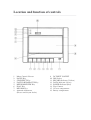
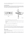
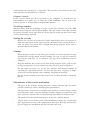
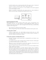
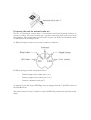
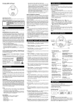
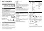
Location and function of controls
___________________________________________________________________________________
1.
2.
3.
4.
5.
6.
7.
8.
Motor Control Selector
PAUSE Key
STOP/EJECT Key
FAST FORWARD/CUE Key
REWIND/REVIEW Key
PLAY Key
RECORD Key
Azimuth Adjustment
(Please consult your dealer)
9.
10.
11.
12.
13.
14.
15.
16.
DC INPUT SOCKET
DIN Socket
RECORD Indicator (Yellow)
DATA Indicator (Green)
POWER Indicator (Red)
Tape Counter
Cassette compartment
Battery compartment
Precautions
___________________________________________________________________________________
The mains adaptor
WARNING: Under no circumstances should the mains adaptor be replaced by a
normal mains plug. The mains adaptor contains components to convert the mains to a
safe, low voltage (dc), for input to the Data Recorder.
There is a thermal fuse build into the mains adaptor and if this blows, you must
replace the adaptor. Please consult your local dealer.
The mains adaptor should not be left plugged into the domestic 13A socket for long
periods if the Data Recorder is not being used.
Do not expose the mains adaptor to rain or moisture.
Do not leave the PLAY key depressed for long periods when not in use, as this may
damage the mechanism.
Other Precautions
When the recorder is not to be used for long periods of time or when operated
extensively with the mains adaptor, remove the batteries to avoid damage from
battery leakage.
Do not install the recorder in a location near hear sources such as radiation or airducts,
or in a place subject to direct sunlight, excessive dust, mechanical vibration, or shock.
Power Supply
A. Mains operation
Plug the adaptor lead into the Data Recorder adaptor socket (marked: 6V. D.C.
POWER IN) [9]. Insertion of this plug automatically disconnects the internal
batteries.
Plug the mains adaptor into a domestic 13A socket and switch on at the socket. The
power indicator [13] will illuminate as an indication that the adaptor is in use.
The ALF03 will now operate using the mains when a mains socket is within reach.
WARNING: Disconnect from the mains when not in use.
B. Battery Operation
Place the recorder face down on a flat surface, and remove the battery-cover. Insert 4
HP11 batteries (or equivalent), carefully observing correct polarity as indicated on the
batteries and in the battery compartment [16]. Replace the battery cover. The power
indicator should not be illuminated during battery operation.
Interference between data recorder and microcomputer
Connect the 7 pin DIN lead from the DIN socket [10] of the Data Recorder to the
Cassette Socket of the Microcomputer.
Cassette insertion
Before inserting a cassette, check the tape tension and make sure that any slack is
taken up. This can be done by inserting a pencil into one of the hub holes and turning
to take up the slack. This simple operation will prevent tape-spill and loop-throwing
both of which can physically damage the tape and spoil recordings.
–
Press the Stop/Eject Key (3) to open cassette holder.
–
Place the cassette in the holder, insert the cassette with the desired side, A or B,
uppermost.
–
Close the recorder by pressing down firmly to ensure cassette is correctly
located.
–
To take out the cassette, press the Stop/Eject Key (3).
NOTE: C15, C30, C60 data cassettes should be used only.
(The use of C90 and C120 cassettes is not recommended with this data recorder). Do
not attempt to load a cassette when the mechanism is engaged. Do not attempt to
remove a cassette without first disengaging any function by using the Stop/Eject Key
[3].
Motor control
The motor control selector [1] is used to switch motor control between the remote
computer and local recorder control.
Computer Control: Motor Start/Stop is controlled by the Computer via the 7 pin
DIN lead, (an appropriate key switch must also be selected, i.e. Play, Fast-Forward or
Rewind).
Manual Control: Motor Start/Stop is controlled directly by the Recorder with or
without the 7 pin DIN plug in place.
The recorder should be in computer control mode during saving or loading of
data/programs.
Saving programs from an Acorn Electron or BBC Microcomputer
Insert a cassette and refer to the Microcomputer System User Guide, Recording
Programs on cassette (Electron page 7 and BBC page 34).
Press the Record Key [7] and Play Key [6] simultaneously until locked. The record
indicator [11] will light up. The recorder is now enabled for recording data under
computer motor control as described in the Microcomputer User Guide. During
recording the recording level is automatically adjusted for optimum results by the
Automatic Level Control (ALC) circuitry.
The Data indicator [12] will light up when blocks of data are being recorded.
If the end of tape is reached during recording, your recorder will shut off
automatically. The Record Key and Play Key will also be released from their locked
positions. Note: If the end of tape is reached before the program has been completely
saved then you must save the whole program on a different part of the tape or the
program will be lost.
When the computer has finished saving the program on the tape, the motor will
automatically stop. If further recording is not required the Stop/Eject Key on the
recorder should be depressed to unload the head mechanism.
Loading programs into a computer from the data recorder
Refer to the Microcomputer System User Guide, Loading programs from cassette.
Insert a recorded cassette into the Cassette Compartment [15]. Press the Play Key [6]
until it locks. The recorder is now enabled for playback under computer control.
The Data indicator [12] will light up when blocks of data are being played back.
When the tape reaches its end, the tape drive mechanism is released and the power is
turned off automatically. The Play Key is also released from its locked position.
The signal output level from the recorder has been optimised for best results with the
Acorn Electron and BBC Microcomputer.
Cue (F.Fwd) and review (rewind)
Manual Control:
The tape can be rapidly advanced or rewound by depressing and latching the FF/cue
key [4] or rewind/review key [5] as appropriate. To stop the tape press stop [3].
If the recorder is in the 'Play' mode (i.e. the PLAY key [6] is depressed), the Cue and
Review keys will not latch on depression but will cause the tape to rapidly advance or
rewind whilst the relevant key is depressed. The recorder reverts back to the 'play'
mode when the Cue/Rewind key is released.
Computer Control:
If the cassette motor has been activated by the computer as described in the
microcomputer user guide (e.g. by using the *CAT command), the cue and review
features operate as described above under manual control.
Use of tape counter
When recording from the beginning of a tape, set the Tape Counter [14] to the '000'
position by pressing the Counter Reset Button. The tape counter shows the positions
of sections recorded on the tape while it is being played so that you may locate those
sections again during playback.
Storing the cassette
–
Replace the cassette in its protective holder immediately after use to protect it
from dust and to prevent the tape from being unwound in the cassette. Store in a
cool, dry place away from direct sunlight and strong magnetic fields such as
speakers and electric motors.
Caution
–
When the tape reaches its end during fast forward or rewind operation it stops
automatically but the motor remains running. Be sure to stop the motor by
pressing the Stop Key [3] or otherwise the tape drive mechanism may be
damaged.
–
Keep the machine and cassettes away from strong magnetic fields, such as close
to large transformers, electric motors, television receivers and loudspeakers.
–
Do not make excessive use of the Fast Forward and Rewind buttons in
searching for a particular item on a cassette; this may cause "stepping" or ridges
in the layers of tape and thus cause jamming, triggering the autostop.
–
Do not touch recording head with screw-driver or other metallic or magnetic
objects.
Maintenance of the cassette mechanism
–
The parts of the machine coming into direct contact with the tape do require
periodic cleaning to ensure continuing good performance.
–
The tape heads (erase head, record/play head) should be cleaned using a cotton
bud moistened with a drop of isopropyl alcohol solution or proprietary tape
head cleaner or, alternatively, by a good quality Tape Head Cleaning cassette.
–
The pinch-roller and capstan shaft may be cleaned in a similar manner.
–
To gain better access to these parts of the mechanism, remove any cassette from
the compartment and leave the compartment door open. Pressing the Play Key
[6] will engage the mechanism and move all parts into view.
–
It will be found easier to clean the pinch-roller if the power source is connected
(batteries or mains) so that the roller and the capstan shaft rotate.
–
Failure to maintain the tape heads in a clean condition will result in program
errors and incomplete erasure.
–
Failure to maintain the pinch-roller and capstan shaft in a clean condition is
likely to cause the tape to entangle and spill out of the cassette.
Demagnetizing the head
Either prolonged use or an accidental contact with a piece of magnetized steel
(screwdriver, scissors, etc) will magnetize the Record/Playback Head causing an
increase in tape noise. In such an event, demagnetize the head using a commercially
available head demagnetizer.
–
–
Be careful not to demagnetize the Erase Head.
When demagnetizing, remove the batteries and disconnect the AC power cord.
Cleaning the cabinet
–
Clean the cabinet with a soft cloth slightly moistened with water or a mild
detergent solution. Do not use solvents such as alcohol, benzine or thinners as
they may damage the finish of the cabinet.
Protection Against Accidental Erasure
–
Normally, anything recorded on the tape is automatically erased when a new
recording is made.
–
It is possible to protect your recordings from accidental erasure by removing the
erase-lock tabs found on the rear of the cassette.
–
When the cassette is held with the recorded side uppermost, the protective tab
will be found on the left of the rear edge of the cassette.
–
All pre-recorded cassettes are protected in this way to prevent accidental erasure
of the commercial recording.
–
"Protected" cassettes may be re-recorded simply by fixing a piece of adhesive
tape over the hole where the tab has been removed. This takes place of the tab
and your machine can now be engaged in the record mode. A "protected"
cassette will prevent the record button from being depressed. If at any time you
attempt to record, and this button will not engage, never force the mechanism or
damage will result. Check that a cassette has been loaded properly and that the
erase-lock tab has not been removed.
Preparing the unit for normal audio use
For use as a monaural cassette unit, i.e. for normal record and playback of music or
speech, it will be necessary to make up a separate connecting lead to that used with
the computer. The connections required at the cassette end of the lead should be made
as indicated in the drawing below:A. When the input is from a stereo source connect as follows:-
B. When the input is from a monoural source:–
Connect input lead to either pins 1 or 4.
–
Connect output lead to either pins 3 or 5.
–
Connect common lead to pin 2.
A standard 5 pin 180 degree DIN Plug may be plugged into the 7 pin DIN socket on
the Data Recorder.
The motor control selector [1] must be in the 'MANUAL' position for operation in this
mode.
Product specification
___________________________________________________________________________________
1.
EQUIPMENT: Data Recorder
2.
ORDER CODE: ALF03
3.
FUNCTION: Program and data storage on C15 up to C60 cassette tape
4.
DESCRIPTION OF OPERATION: Mono data recorder with switchable motor
control facility
5.
CAPACITY: Approx 30 Kbytes/side on C15
Approx 120 Kbytes/side on C60
6.
FORMAT: 300 or 1200 baud computer user tape standard 1200 and 2400HZ
tones.
7.
SPEED: 4.7 cm/second - 2% to +3%
Fast forward and rewind in 100 seconds for C60
8.
CONTROLS: 6 key mechanism for "pause", "play", "stop and eject", "cue/fast
forward", "review/rewind" and "record".
9.
COMPUTER/MANUAL CONTROL. The motor can be controlled from a
remote computer if this facility exists.
10. INDICATORS: Power, data and Record indicators. Tape counter with reset
button.
11. SIGNAL CONNECTIONS: 7 pin DIN for input/output/motor control
Input signal range 5mV to 500mV
Input impedance 40k Ohm
Output signal 500mV RMS at φdb tape level.
12. POWER IN: 4 x HP11 1.5 volt cells or ALF03 mains adaptor
13. APPROVALS: To conform to BS415:79
14. OPERATING TEMPERATURE: 0 degree C to 35 degree C.
15. ACCESSORIES INCLUDED: ALF03 mains adaptor; 7 pin DIN to 7 pin DIN
lead and this User Manual.
This apparatus has been produced to comply with Directive No 76/889/EEC
(CISPR14)