1
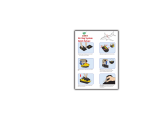
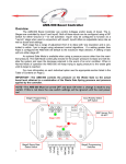
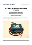
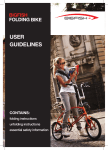
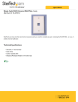
USER MANUEL
AUTOMATIC TIRE INFLATOR
# MW-60, MW-60-4WAY & MW-64HP
TIRE EQUIPMENT
MANUFACTURER
1.866.409.RACK
WWW.MARTINSINDUSTRIES.COM | [email protected]
PARTS
Verify that the following components are complete in the package.
INFLATOR BODY WITH 5 FEET (1.52M) POWER CORD
MW-60
150 PSI X 1outlet
MW-64Hp
195 PSI X 1outlet
MW-60-4way
150 PSI X 4 outlets
POWER SUPPLY, INLET, OUTLET, EXHAUST & BEEPER
MW-60 & MW-64Hp
110-240 V
(50-60 Hz)
AIR HOSE WITH
1/4” CHUCK
1/4”
Connector
1/4”
Quick connect
MW-60-4way
Exhaust
Beeper
(Speaker)
MW-60 & MW-64Hp
25 feet (7.6 M) Air Hose
1/2”
Quick connect
MW-60-4way
4 hoses of 8 feet (2.4M)
1
PARTS
Verify that the following components are complete in the package.
INSTALLATION SCREWS
M6*38 Screw - 4 pcs
HOOK AND SCREW KIT
Hose hook and M6*38 Screw
INSTALLATION
1. Unpack the unit
2. Hold the unit up on the wall and mark
where the four (4) holes are to be drilled.
3. Secure the unit using suitable fastener
4. Connect the air supply to the unit.
5. Connect the power supply; refer to the rating
label for the correct power requirements.
WARNING
Ensure that the product is connected
to the correct power and air supply;
refer to rating label and general specifications.
2
SWITCH FUNCTIONS
Navigation menu function,
decrease pressure in operating mode
Navigation menu function,
increase pressure in operating mode
Select function: Select measurement unit/select
OPS setting nitrogen cycle purge (on MW-64Hp model only)
Select function: Confirm / Start Inflation / Stop.
Press this button to turn on the inflation process when the
tire pressure is less than 3 psi, 20 kPa or 0.2 bars
LCD CRYSTAL DISPLAY
1. Unit display
2. Pressure
3. “Select” function
4. Inflation cycle indicator bars
1.
2.
3.
4.
FUNCTION AND OPERATION
NAVIGATING THE MENUS
Press (i) to access the select functions mode, then select the unit of measurement; press (i) 2 times to enter the OPS setting,
press (i) 3 times to enter the purge nitrogen cycle functions (on MW-64Hp model); press (i) 4 times to exit the select functions
mode without saving your previous selections.
UNITS OF MEASUREMENT
The automatic inflator offers you a choice of 4 tire pressure measurement units: Kpa, Bar, Kg/cm2 and Psi. The selected unit
becomes the default measurement unit; it will not be necessary to change the unit for future use. To choose the desired unit
of measure:
A. Press ( i ); (SET) will be displayed on screen, and the current measurement unit will flash.
B. Press (+) or (-) to select the desired measurement unit.
C. Press ( ) to confirm your selection.
OVER-PRESSURE SETTING (OPS)
A. Press ( i ) twice; (SET) and (OPS) will be displayed on screen, and the OPS indicator will flash.
B. Press (+) or (-) to select the OPS value.
C. Press ( ) to confirm your settings. If the OPS value is not equal to zero, the OPS indicator will be visible on the LCD screen.
Important: The sum of the selected inflation pressure and OPS pressure must always be less than the maximum pressure
allowed by the tire manufacturer.
3
FUNCTION AND OPERATION
INFLATION AND DEFLATION
A. Press (+) or (-) to select the target pressure.
B. Connect the air hose to the tire valve, the tire inflator will automatically start.
C. When inflation has been completed, the tire inflator will automatically stop and will emit a beep to alert the user.
D. The tire is now inflated; you can open the door and disconnect the air hose.
The tire inflator will not start automatically if the pressure is lower than 3 psi or 0.2 bars.
You must press ( ) for 2 seconds to manually start the inflation process.
During the inflation phase, the device automatically checks the tire pressure, and the inflation cycle indicator bars will become
active. The indicator bars will move from left to right during inflation, and from right to left during deflation
NITROGEN PURGE CYCLE (on MW-64Hp model only)
A. Press (i) 3 times (SET) and (N2) will be displayed on screen.
B. Press (+) or (-) to set the number of Nitrogen Purge Cycles.
C. Press ( ) to confirm your settings. If the Nitrogen Purge Cycle value is not equal to zero, the N2 indicator
will be visible on the LCD screen.
D. The Nitrogen Purge can be set up to 9 cycles.
REMARK:
OPS SETTING
When OPS function is on, device will inflate to target pressure plus OPS value first, then deflate to tire pressure desired, for example:
A final target of 32 psi or 2.2 bar with an OPS setting of 16 psi or 1.1 bar gives a sum of 48 psi or 3.3 bar. This sum of 48 psi or
3.3 bar is the Over Pressure setting for tire. Tire will inflate to the sum value and deflate to the final target pressure.
NITROGEN PURGE CYCLE (on MW-64Hp model only)
When N2 purge function is on, the device will inflate to the final target pressure first, and then deflate to the
N2P deflate-lower-limit-setting, the device will inflate again to the final target pressure. If 1 N2P cycle was set, then
the cycle is now completed. If more than 1 N2P cycle was set, the purge routine (deflate/inflate) is repeated according to
the number of purge cycles set. The deflate lower limit default setting is 0.3bar or 5psi.
WARNING
1. Please check carefully to ensure that no part is damaged, so to ensure safety and formal operation.
2. During inactivity period, please package the inflator and keep it away from damp, heat, impact, etc.
3. The device can be installed outside, but a shelter is suggested, so to protect the equipment from bad weather, extend
the service life.
4. Since directly compressed air contains oil and water, water is from condensation and oil is from the compressor,
water and oil will strongly destroy the device, so it is important to filter them out first from the system.
5. Keep the compressed air inlet pressure within 10.5 bar (1050 kpa / 150 psi / 10.5 kg/cm2).
6. Electrical connection should be carried out by qualified people strictly according to the related regulation applicable at
the place where the inflator is used.
7. Protection switch is not supplied with the device; please install the protection switch on your own if necessary.
4
FUNCTION AND OPERATION
MAINTENANCE
1. Daily Maintenance
The device does not require particular maintenance; routine check of the pneumatic connection is suggested.
Daily maintenance should be carried out by qualified personal.
2. Special Maintenance
All the maintenance not included in Daily maintenance is special maintenance, which should be done by qualified personal.
Authorized agent could be contacted for it.
TROUBLESHOOTING
PROBLEMS
POSSIBLE CAUSES
SOLUTIONS
Air Leaks
Leak in the connections
Check the pneumatic connections
The inflator works but
does not inflate
Obstruction in filters or in the air system
Clean the filters and check the air hose
No display
Problem with the power supply
Check the power source and
electrical connection
Inflation does not start,
but the pressure has been
selected and the air hose is
connected to the tire valve
The air hose is
improperly connected
The door valves are not connected
or are poorly adjusted
The tire pressure is below 0.2 bars (3psi)
Check the air hose connection and
ensure there are no leaks
Check the valve connections
and/or adjust the door valves
Press for 2 seconds
The inflator deflates very slowly
The silencer outlet is blocked
Remove and clean the silencer
outlet and reinstall it
Er1
The pressure sensor is broken
The inflator must be replaced
Er2
The pressure is unstable,
the connector hose is defective
Replace the connector hose or
reconnect the hose to the tire
Er3
Tire connected, the tire pressure
is too high (150 Psi)
Stop inflating the tire immediately
and disconnect it from the system
Er4
Wrong connections of air inlet and outlet
Refer to wiring diagram and connect
the magnetic valve accordingly
Er5
Low voltage
Check the electrical power source
Er6
Calibration error
The automatic inflator needs to be
calibrated, contact Martins Industries
Er7
Calibration error
The automatic inflator needs to be
calibrated, contact Martins Industries
Er8
The air source is lower than the set pressure
Stop inflating the tire
5
GENERAL SPECIFICATION
Inflation Range:
0.5-10 bar (1000 kpa / 145 psi / 10 kg/cm2)
Accuracy:
+/-0.29 psi (+/-0.02 bar)
Max Inlet Air Supply:
150 psi (10.3 bar)
Supply voltage:
AC 110~240V (50~60Hz)
Watt:
12 W Max.
Working Temperature:
-10°C~50°C (14°F~122°F)
Relative Humidity:
up to 95% RH non-condensing
Material:
Die cast Aluminum Enclosure
Degree of Protection:
IP66
Dimensions:
9” X 10.5” X 3.5” (23 X 27 X 8.5 cm)
WIRING DIAGRAM
WARRANTY
The inflator includes a 1-year warranty from the billing date, but is null and void if the inflator has been damaged through misuse,
faulty installation, improper maintenance or accidental damage, or unauthorized modifications or repairs.
6
CERTIFICATIONS AUTOMATIC INFLATOR
7
1.866.409.RACK
WWW.MARTINSINDUSTRIES.COM
[email protected]