1
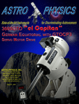
ASTRO-PHYSICS
3600 GERMAN EQUATORIAL WITH
GTO SERVO MOTOR DRIVE
For Mounts shipped starting in October, 2008. Beginning with Serial Number 36003
MODEL 3600GTO PARTS LIST – MODEL GTOCP3
3
FEATURES AND SPECIFICATIONS
4
INTRODUCTION
5
Why Polar Alignment is Important
5
ASSEMBLY DIAGRAM
6
INITIAL MOUNT ASSEMBLY AT YOUR OBSERVING SITE OR OBSERVATORY
7
Assemble Pier (purchased separately) or Attach 3600 Flat Surface Adapter to your Existing Permanent
Pier.
7
Assemble Polar Axis Assembly to Pier and Attach Azimuth Adjuster
8
Prepare to Mount the Declination Axis
9
Mount the Declination Axis onto the RA Axis.
11
Attach the GTOCP3 Control Box, optional GTOELS Limit Switch / Encoder Box and Cables
13
Polar Alignment – Part 1 – Rough Alignment
14
Altitude and Azimuth Adjustments - Rough polar alignment
14
The Azimuth Adjustment System
15
The Altitude (latitude) Adjustment System
16
Procedure for rough alignment
16
The Daytime Polar Alignment Routine in Brief
17
FINAL SYSTEM ASSEMBLY AND CABLE MANAGEMENT
Attach Mounting Plate (purchased separately)
CABLE MANAGEMENT
Mount Control Cables – Servo, Limit / Homing Switch and Precision Encoder
Accessory Cables
Attach Counterweight Shaft and Counterweights
Attach Mounting Rings and Scope (purchased separately)
Understanding the R.A. and Dec. Clutches
Balancing Your Telescope
First, Balance the Declination Axis
Second, Balance the Polar Axis
Polar Alignment – Part 2 - Fine Polar Alignment
Tips on Making the Fine Adjustments to the System
Methods for fine polar alignment
18
18
20
20
20
23
23
24
25
25
25
26
26
27
POWER CONSIDERATIONS
28
SERVO MOTOR DRIVE
31
GTO Control Box – Model GTOCP3
Servo Cable Connections
12V Connector
POWER Indicator Light
KEYPAD Connector
31
32
32
32
32
1
RS-232 Connectors
FOCUS Connector
RETICLE Connector
AUTOGUIDER Connector
+6V Connector
N and S Switch
Drainage Holes
Pre-loaded PEMPro Curve
32
33
33
33
33
33
33
31
GTO KEYPAD OPERATION
34
PULSEGUIDE BY SIRIUS-IMAGING
34
PEMPRO V. 2.X (LATEST RELEASE) BY SIRIUS-IMAGING
34
OPTIONAL 3600GTO LIMIT / HOMING SWITCH SYSTEM (36LSS)
34
OPTIONAL 3600GTO PRECISION ENCODER SYSTEM (ON THE 3600GTOPE)
34
SLEWING YOUR MOUNT IN BELOW FREEZING TEMPERATURES
35
MOUNT CARE, CLEANING AND MAINTENANCE
36
Care
Cleaning and Touch-up
Routine Mount Maintenance
36
36
36
ADDITIONAL TIPS AND SUPPORT
36
TROUBLESHOOTING
37
CHARACTERIZING THE DEC AXIS MOTIONS
40
ASTRO-PHYSICS MOUNTING PLATE FASTENER CHART
41
PLEASE RECORD THE FOLLOWING INFORMATION FOR FUTURE REFERENCE
MOUNT SERIAL NUMBER:
______________________________
KEYPAD SERIAL NUMBER:
______________________________
GTOCP3 SERIAL NUMBER: ______________________________
GTOELS SERIAL NUMBER: ______________________________
PURCHASE DATE:
______________________________
2
ASTRO-PHYSICS
3600GTO “El Capitan” GERMAN EQUATORIAL
WITH GTO SERVO MOTOR DRIVE
For Mounts shipped starting in October, 2008. Beginning with Serial Number M40003
MODEL 3600GTO PARTS LIST – MODEL GTOCP3
1
1
1
1
1
1
1
1
1
1
7
1
Var.
1
1
Polar axis assembly (right ascension-R.A.) with Integrated Pier Adapter
Azimuth Adjuster Assembly with two 1/4-20x1 3/4” socket cap screws for mounting
Servo Control Box GTOCP3
Declination (Dec.) axis assembly with two 3/8-16x1” and four 3/8-16x1 1/2” socket head cap screws for attachment
31.5” (30.0” usable) Stainless counterweight shaft (2.5” dia.) with machined, black-anodized, safety stop
Y-cable with grommets for internal cable routing – R.A. portion is 19.5” long and Dec portion is 35” long (inside RA)
22” Servo Extension Cable for connection to GTOCP3 Control Box
D.C. power cord (cigarette lighter adapter on one end) - 8’ long
Straight-through Serial Cable – 15 feet long – for connection to computer
GTO Keypad controller with 15’ coiled cable, Instruction Manual and installed Keypad Protector (KEYPRO)
3/8-16 x 3/4 socket cap screws with seven 3/8 ID x 7/8 OD flat washers – for attachment to pier or 3600FSA
Hex key set with additional 3/8” long arm hex key
Cable stays (some attached), Velcro straps, 1 - keypad lanyard strap etc.
PEMPro™ V.2.x – Full Version Periodic Error Management software with Polar Alignment Wizard (CD-ROM)
PulseGuide™ by Sirius Imaging – remote control utility for improved guiding (CD-ROM)
In order to fully assemble your mount, you will need the following items sold separately:
•
Telescope mounting plate: We recommend our 22” x 12.9” Dovetail Saddle Plate (DOVE3622) and the 22” x
9.9” Dovetail Sliding Bar (SB3622).
•
Pier: Permanent Pier (12” Min. diameter recommended), 12” O.D. ATS Portable Pier or other pier
•
3600 Flat Surface Adapter (3600FSA): This will be required for most of the pier options available to you.
•
Counterweights: 30 lb. (30SCWT) – Up to 12 counterweights will fit on the standard counterweight shaft.
•
DC Power Source: 14 to 18 volts at 10 amps is recommended.
o
BEST CHOICE: Filtered, Regulated Power Supply (Household AC to DC converter) – we recommend
our 15 volt, 10 amp supply for users with 110 volt 60 Hz AC power. (PS15V10A).
o
See additional information in the Power Considerations section of this manual.
Many of these items will be discussed throughout these instructions. Several additional options are available:
•
Limit Switch System for the 3600GTO (36LSS): Switch system for establishing safety parameters past the
meridian and for homing functions.
•
Precision Encoder System for the 3600GTO (on the 3600GTOPE): State-of-the-art technology for virtual
elimination of periodic error in real-time. Note: This option can NOT be purchased as an upgrade after the
mount is complete. It must be ordered before the mount is built.
•
11.5” counterweight shaft extension (M3655):
•
Autoguiding Accessories: Various imaging and CCD based guiding configurations can take advantage of
the 3600GTO’s autoguider port. The autoguider port receptacle (RJ-11-6) uses the industry standard SBIG ST4 wiring setup.
•
Extension cable for keypad: Please call Astro-Physics to obtain a quote on the length of extension cable you
need.
For balancing heavier loads.
Note on Encoders: Mounted shaft encoders for use with digital setting circles can not be used with the 3600GTO. They
are not needed since the go-to functions of the mount are so much more accurate. The encoder that is built into the servo
motor itself has a resolution of 0.05 arc seconds vs. 324 arc seconds for mounted encoders.
Do not confuse shaft encoders with the Precision Encoder System that is an option with the 3600GTO mount. The
Precision Encoder System, which is detailed later in this manual, is for real-time periodic error reduction.
3
FEATURES AND SPECIFICATIONS
R.A. worm wheel:
Aluminum - 13" (330mm), 256 tooth
Dec worm wheel:
Aluminum - 13" (330mm), 256 tooth
Worm gears:
Brass - 1.41" (35.8 mm) diameter
R.A. shaft:
4.72" (120mm) diameter with 4.02" (102mm) clear inside diameter
R.A. axis bearings:
7.09 " (180mm) diameter deep groove ball bearings
Dec shaft:
4.72" (120mm) diameter with 4.02" (102mm) clear inside diameter
Dec axis bearings:
7.09 " (180mm) diameter deep groove ball bearings
Counterweight shaft:
31.5” overall, 30.0” useable length, 2.5” diameter, stainless steel, removable with Safety Stop
Latitude range:
15 - 70 degrees
Azimuth adjustment:
Approximately 14 degrees (+/- 7 deg.)
Motors:
Zero-cogging Swiss DC servo motors – 2 for each axis
Power Consumption:
0.6 to 1.0 amps at the sidereal rate – depending on voltage, worm mesh and other factors
3.0 to 6.0 amps with both motors slewing simultaneously at 720x – depending on voltage, worm
mesh and other factors
Power requirements:
15 VDC at 10 amps – suggested range: 14 to 18V – See additional information in the Power
Considerations section of this manual. Our 15 Volt, 10 Amp supply (PS15V10AC) is ideal.
Weight of mount:
Equatorial head:
Dec axis:
R.A axis:
Counterweight shaft:
Capacity of mount:
Approximately 300 lb. (136 kg) scope and accessories (not including counterweights), depending
on length. Will accommodate Astro-Physics and similar refractors up to 300 mm f12, 20 - 24"
Cassegrains and Richey-Chrétiens. Multiple scope setups can also be deployed.
These are only guidelines. Some telescopes are very long for their weight or heavy for their size
and will require a larger mount.
205 lbs. (93 kg)
84 lbs. (38kg)
121 lbs. (55kg)
42 lbs. (19kg)
4
INTRODUCTION
The 3600 German equatorial was designed to meet the needs of the advanced observer who requires a mount with
maximum strength and rigidity for today’s large imaging instruments. The excess material in both axes has been carved out
while retaining a heavily ribbed structure for internal strength and rigidity. The axes can be separated for transport to a
remote dark site, but this mount is primarily intended as an observatory platform for large loads and critical applications.
The DC servo motor drive with GTO computer system, the keypad with its digital display screen, and the included
PulseGuide™ and PEMPro™ v.2.x software (most current version) all combine to offer extraordinary sophistication for
today’s observer. We have employed two of the precise Swiss DC servo motors on each axis to provide the extra power
needed for large loads and to smooth out the power curve of the system for incredibly smooth operation, especially in
tracking and guiding. Optional precision encoders for real-time periodic error elimination and limit switches for safety in
remote observatories are available as upgrade accessories when the mount is ordered. Whether you enjoy visual
astronomy exclusively or plan an aggressive astrophotography or CCD imaging program, this mount will allow you to
maximize your night out under the stars.
The advanced keypad features allow you to slew automatically to objects in a wide range of databases as well as any
R.A./Dec coordinate. A large selection of common names for stars and other objects makes your selection a snap. The rapid
slew rate of 3 degrees per second (720x) allows you to locate objects very quickly and accurately. You will be very pleased
with the intuitive operation of this keypad. There are no complicated sequences of keystrokes to remember. It is so easy to
use that even if you don’t use it for a few months, you will feel at home with the keypad very quickly.
PulseGuide™ is a stand-alone Windows (98, ME, 2000, NT4, XP, Vista) utility that provides complete remote control of all
Astro-Physics GTO mounts. It derives its name from its most distinctive feature, pulse guiding, which can improve unguided
tracking. Specifically, it can help correct tracking errors caused by polar misalignment and atmospheric refraction. You can
also train PulseGuide™ to track objects moving relative to the stars, such as asteroids, comets, and the moon. In addition to
pulse guiding, PulseGuide™ also has many useful utility features. PulseGuide™ was written by Ray Gralak of SiriusImaging. Please refer to his website http://www.pulseguide.com for further developments and enhancements.
PEMPro™ (Periodic Error Management Professional) is a Windows software application that makes it easy to characterize
and reduce periodic error. PEMPro™ will analyze the performance of any mount that is equipped with a CCD or supported
video camera and compatible camera control software. PEMPro™ gives you powerful tools to program your mount's
periodic error correction firmware to achieve the best possible performance for your mount. PEMPro™ dramatically
improves guided and unguided imaging resulting in better images and fewer lost exposures. The current full version of
PEMPro v.2.x is included with the 3600GTO. While the native periodic error of your 3600GTO will be 5 arc seconds or less,
you can reduce it even further to maximize performance without auto-guiding. As an added bonus, all 3600GTO mounts
will come pre-loaded with the custom-fitted PEMPro corrections from our extensive individual testing that is performed on
each and every mount.
The 3600GTO is most at home in a permanent observatory, but unlike most observatory-class mountings, it can go portable
for remote star parties. This is the perfect mount for a large refractor, Newtonian, Cassegrain, Richey-Chrétien or astrograph,
and it is perfect for multiple instrument imaging setups.
In order to maximize your pleasure on your first night out, we
recommend that you familiarize yourself with the assembly
and basic operation of the mount indoors. The temperature
will be comfortable, the mosquitoes at bay, and you'll have
enough light to see the illustrations and read the manual.
Please take particular note of counterbalancing, use of the
clutches and operation of the keypad controller.
Why Polar Alignment is Important
Polar alignment compensates for the Earth’s rotation.
If you were to take a long exposure photograph with Polaris
(often called the north star) in the center of the field, you
would discover that all stars seem to revolve around Polaris.
This effect is due to the rotation of the earth on its axis.
Motor-driven equatorial mounts were designed to
compensate for the earth's rotation by moving the telescope
at the same rate and opposite to the earth's rotation. When
the polar axis of the telescope is pointed at the celestial pole
(polar aligned) as shown in the diagram at right, the mount
will follow (track) the motions of the sun, moon, planets and
stars. As a result, the object that you are observing will
appear motionless as you observe through the eyepiece or
take astrophotos. Please study the sections detailing polar
alignment procedures later in the manual.
5
ASSEMBLY DIAGRAM
6
INITIAL MOUNT ASSEMBLY AT YOUR OBSERVING SITE OR OBSERVATORY
Assemble Pier (purchased
separately) or Attach 3600 Flat
Surface Adapter to your Existing
Permanent Pier.
The 3600GTO will be carrying many pounds and many
thousands of dollars worth of equipment, all the while
performing at levels measured in arc seconds and
fractions of arc seconds. To achieve the mount’s
potential level of performance, it must be on a solid and
secure pier.
Be particularly aware of the issue of tube roundness at
the top of any permanent or portable pier where you
intend to use an open pipe top for the mount. The
mount’s integral Pier Adapter Plate must be able to fit
into the opening at the top without either undue
resistance or excessive slop. The mount’s Pier Adapter
Plate is machined on a lathe and is machined to very
high tolerances. It is as perfectly round as modern CNC
machining can produce. The pier component that is to
receive it should have similar precision. Most “round”
pipe is not perfectly round without either some machining
work, or the insertion of a plug to “force” the pipe walls
round. The difficulty in making an open pipe round
enough for a good fit is why we strongly recommend the
use of a flat top plate and our 3600 Flat Surface Adapter,
whether on a portable or a permanent pier.
•
A permanent pier with a deep footing and a flat
surface on top is highly recommended for an
observatory situation. We suggest that for
ease of installation, the pier should incorporate
a 12” to 16” diameter top plate of steel or
aluminum that is drilled and tapped with eight
3/8-16 holes on a 10.788” bolt circle as shown
in the drawing at right. Then simply bolt the
3600 Flat Surface Adapter to the top for a
perfect fit. Alternatively, your permanent pier
can have an open top with an 11.500” inside
diameter and eight holes 0.500” down from the
top as shown in the drawing at right.
•
For portable use, we are currently offering the
ATS 12” Portable Pier.
•
Other portable piers may also be available
from other manufacturers. Any portable pier
that you choose must either accept our 3600
Flat Surface Adapter (3600FSA) or else
adhere strictly to the specifications shown
above. We recommend that your pier employ
our 3600 Flat Surface Adapter for best results.
•
For occasional portable use with light loads, a 10” diameter pier like an Astro-Physics or ATS Portable Pier may
also be used. Simply attach a 1200 Standard Pier Adapter (1200SPA) to the 10” pier, and remove the Mount Lock
Knobs, the Azimuth Adjuster Block and the Center Pivot Screw from the 1200SPA. Now bolt the 3600 Flat
Surface Adapter onto the 1200SPA using the tapped holes for the lock knobs and center hole, and you are ready
to go.
7
Assemble Polar Axis Assembly to Pier and Attach Azimuth Adjuster
In order to track the motion of astronomical objects, the polar
axis must be positioned so that an imaginary line drawn
through the center of the axis points toward the celestial pole.
Refer to the diagram at the front of this manual for a graphical
representation. At this stage of the assembly process, you
want to position the mount so that it points roughly north.
1.
Orient the pier. Set your pier up so that the hole
pattern for the mount’s Pier Adapter Plate is
oriented as shown in the preceding diagrams and
the photo at right, with side mounting holes at each
of the four compass points.
2.
Set the RA Axis in place. Carefully set the
3600GTO Right Ascension Axis into the pier top or
the 3600 Flat Surface Adapter (3600FSA). It is
ideal to have three people involved in this
operation: two people lifting the axis – one from
each side and the third person guiding the Pier
Adapter Plate into the opening of the pier top or
3600FSA. Depending on the configuration of your
observatory, you may also wish to employ a hoist or
other lifting device. A strap can be easily run through
the axis to facilitate a mechanical lifting device.
3.
Line up the Pier Adapter. If the side thru-holes in the
pier or 3600FSA are not perfectly lined up with the
tapped holes in the mount’s Pier Adapter Plate, line
them up by grabbing hold of the Azimuth Adjuster Block
on the bottom rear of the mount and using it to turn the
Pier Adapter Base. Do not try to line up the holes by
turning the large square base of the mount. Since this
is a Rotating Pier Adapter, simply turning the base
without the Azimuth Adjuster in place will turn the top
plate without also turning the part of the plate that is
inside the pier top or 3600FSA. If you have a pier top
that is rather tight, you may need to attach the Azimuth
Adjuster (see the next step) before securing the mount to
the pier so that you can line the holes up by turning the
mount’s big square base.
4.
Attach Azimuth Adjuster. Attach the 3600GTO’s Heavy
Duty Azimuth Adjuster to the bottom rear of the mount’s
bottom plate. To do this, first unscrew (loosen) each of
the knobs far enough that the azimuth adjuster block on
the bottom of the plate will easily fit between the ends of
the two rods.
Install the Azimuth Adjuster Assembly as shown in the
photo at right, and fasten with the two 1/4-20 x 1 3/4”
socket head cap screws that are provided with the
Azimuth Adjuster Assembly.
Once the Azimuth Adjuster is installed, you can snug
the knobs up against the Azimuth Adjuster Block and
now when you rotate the mount base within the pier it
will turn the bottom part of the Rotating Pier Adapter so
that you can line up the holes for attachment if you were
having trouble moving the base via the azimuth adjuster
block alone.
8
5.
Secure the RA Axis to the pier. When you have the holes lined up, fasten the mount to the pier top or 3600 Flat
Surface Adapter using seven 3/8-16 X 3/4” socket head cap screws and 3/8 flat washers. (There is not a tapped
hole in the pier adapter plate immediately behind the Azimuth Adjuster Block.) Be sure to start all seven cap
screws (with their washers) before tightening any of them. Then snug all seven cap screws down before finally
tightening them all securely.
Prepare to Mount the Declination Axis
1.
Set the RA latitude higher. Your RA axis will have
been shipped, and should be transported in a low – but
not quite bottomed out – latitude position of about 18
degrees. At this point in the assembly process, you will
want to raise the latitude adjustment to around 35 to 40
degrees, even if you are at a lower latitude. The reason
for this is to provide an angle for the declination axis to be
in a relatively balanced state when it is set in place on the
RA axis. This will make it much easier to align the bolt
holes and secure the axes together without also having to
hold the 84 lb. dec axis in place against gravity.
To raise the latitude or altitude setting, first loosen the
forward and the rear polar axis lock-down bolts in the
curved slots on the sides of the polar forks as shown at
right. Do not loosen the larger center polar axis pivot
bolt. The Hand Wheel’s crank handle will be in the folded
position. To unfold the handle for altitude adjustment,
pull up on the handle, and then simply fold it out as shown
in the photo. Turn the Altitude Adjustment Hand Wheel
counter-clockwise to raise the angle of the RA axis to
around 35 or 40 degrees. You may find an inclinometer
handy as shown below.
If you are setting up your mount at a latitude between 35
and 40 degrees (or close to that) anyway, you might also
consider performing your rough alignment before actually
mounting the declination axis onto the RA axis. At higher or
lower latitudes, there is no point in setting the rough altitude
until after the declination is safely mounted. See the section
on rough alignment later in this Initial Mount Assembly
section.
9
2.
Prepare Mating Surface for Declination Axis. The carved out
face of the RA axis’ declination mating surface shows three
indentations for the clutches. One of these is centered between
two of the attachment bolt holes while the other two are each off
center of a single attachment hole. You will also note that there
are two small indicator grooves or indentations on opposite sides
of the mating face and a third small groove on the outside of the
mating hub, just below the clutch that is centered between the
two bolt holes.
The correct orientation of the mating surface for attachment of
the dec axis is with the clutch that is centered between the two
holes (and therefore also the small groove on the outside of the
mating hub) down at the 6 o’clock position. This will have the
other two clutches at the 2 o’clock and 10 o’clock positions and
the two small grooves at 3 o’clock and 9 o’clock. This
orientation is shown in the photo at right. The mount will have
been shipped already in this position. If your mount is being
reassembled and was not disassembled from the classic German
equatorial pose (instrument pointing at the pole as in the AstroPhysics Park 3 position), you may need to loosen the clutches
and turn the hub to the proper position. Be sure to re-tighten the
clutches before installing the dec axis. (See the section on clutches later in the manual.)
3.
Make the Cables Accessible. The mount is shipped and
may be transported with the “Y” cable attached to the RA
motor/gearbox and the RA cable access plate on the rear of
the RA axis. The declination leg of the cable will be coiled up
inside the hollow RA shaft, and will probably be situated all the
way back against the rear RA rear cover plate. To make it
easier to access the dec cable once the dec axis is installed,
reach into the axis and carefully pull the cable forward and out
of the axis. Slide the rubber grommet for the dec cable all the
way forward until it is tight against the plug for the dec
motor/gearbox. Then re-coil the cable into the RA axis
positioned so that it will be easy to reach once the declination
axis is attached. DO NOT have any of the cable actually
hanging out of the RA axis, or it will get pinched when the
declination axis is set in place. The photo at right shows a
good arrangement.
10
Mount the Declination Axis onto the RA Axis.
At 84 lbs. (38 kg.), the dec axis is not quite as unwieldy as the
RA axis. However, it must be lifted higher than the RA. You
may still wish to employ a mechanical lift if available. If lifting by
hand, we again recommend getting help as described above –
two to lift; one to guide.
1.
Check the Cables in the Declination Axis. If you
have ordered your 3600GTO with the optional limit
switches (36LSS), you will also have a cable coiled up
inside the declination axis. Make sure that this cable
is not protruding from the mating surface of the
declination axis. As mentioned in the instruction
above, you do not want to pinch this cable between the
mating surfaces of the two axes.
2.
Mount the Dec Axis. The declination axis should
first be positioned with the declination hub up and the
counterweight shaft adapter down. It will have been
shipped (and should be transported) with the
declination mating surface bolted down to the shipping
crate. It may be best to lift the axis into an
intermediate position like a work bench and turn it over
there. Then, carefully lift the declination axis onto the
RA axis, keeping the dec hub up and the CW shaft
adapter down.
The dec axis will fit into the mating surface of the RA hub. Once it is
in place, if you have pre-set your RA altitude to 35 – 40 degrees as
instructed above, the axis will stay in place and will not fall off. For
safety sake, however, we would recommend that you not let go
completely until you have one of the mounting bolts started.
3.
Secure the Declination Axis. The first step will be to align the three
holes on each side of the declination axis with the corresponding holes
in the mating surface of the RA axis. If you pre-positioned the RA
mating surface as described above and you set the dec in place with
the dec hub straight up and the CW shaft adapter down, they should
already be very close.
Carefully turn the dec housing on the RA mating surface until the holes
are lined up. The small groove on the outside of the RA mating hub
should be in line with the CW shaft if you have everything oriented
correctly.
When everything is lined up, insert the shorter 3/8-16 x 1” Socket Cap
Screws in the center attachment holes on each side and start each
bolt in a couple turns. Attach the four longer 3/8-16 x 1 1/2” Socket
Cap Screws in the outside attachment holes on each side of the dec
axis. Lightly snug all six bolts. Then, tighten the center bolt on
each side, and lastly, tighten the four outside bolts.
11
4.
Retrieve and Attach the Declination Servo Cable. To attach the declination servo cable, you will first need to
remove the dec axis’ servo cable port plate from the axis body. Use a Phillips screwdriver for this as shown in the
photo. Once the port plate is removed, reach into the declination axis to retrieve the Declination Servo Cable from
the inside of the RA axis. You may need a step stool or small step ladder to do this. In our experience, we have
found it easiest to first pull the cable on out through the declination hub so that you can be sure that nothing is
tangled. This will also allow you to be sure that the rubber cable grommet is in position to be easily fed through the
cable port.
Next, you simply get a good grip on the plug and grommet and plunge your hand back into the declination hub to
feed the plug and grommet out through the cable port in the declination axis. The cable port plate can then be
slipped over the plug end of the cable. The flat side of the cable port plate should be facing outward – the side with
the recessed face will face into the axis. Carefully work the rubber grommet onto the cable port plate.
12
Attach the GTOCP3 Control Box, optional GTOELS Limit Switch / Encoder
Box and Cables
The GTOCP3 control box is attached to the built-in bracket as shown below. (This will be on the west side of the polar fork
for those in the northern hemisphere, and the east side of the fork for those in the south.) The procedure is illustrated
below.
1.
Prepare the control box bracket. Begin by removing the two small buttonhead screws near the back edge of the
fork using a 3/32 hex wrench. These will be used to attach the cable stays once the servo cable is attached. Next,
loosen the two thumbscrews on the top of the bracket until they are flush on the bottom lip of the bracket.
2.
Attach GTOCP3. Tilt the GTOCP3 Control Box into the bracket’s bottom dovetail fitting. Snug down the two
thumbscrews to hold the control box in place.
3.
Attach Servo Cable. Attach the 22” Servo Extension Cable (CABGTOR22) that was included with the mount to
the control box and to the receptacle on the rear plate of the RA axis.
4.
Attach Cable Stays. Slip the cable stays over the cable and attach to the polar fork using the buttonhead screws
that you removed in step 1.
The optional GTOELS control box for the Precision Encoder System and for software control of the Limit / Homing Switch
System is installed in the same basic fashion on the opposite side of the polar fork. For detailed instructions, see the
separate documentation that pertains to the options you have selected.
13
Polar Alignment – Part 1 – Rough Alignment
We recommend that you accomplish your polar alignment in two
or more phases – rough alignment and fine alignment (or
successively finer alignments). The purpose of performing a
rough alignment before final system assembly is to minimize the
amount of adjustment that is necessary once the mount is fully
loaded with equipment and counterweights.
NOTE: A polar alignment scope cannot be used with the
3600GTO. There were a number of considerations that made a
polar scope impractical for the 3600GTO.
•
•
•
•
•
•
The mount’s polar fork geometry and rear altitude
adjuster would interfere at all but the lowest latitudes.
A huge sight hole would have been required on the top
of the dec axis to avoid vignetting of the alignment stars
around the periphery of the polar scope.
Internal cabling would interfere with the operation of the
polar scope.
An externally mounted polar scope (i.e. on a bracket on
the side of the axis) does not give satisfactory results.
The mount will rarely be used as a portable mount.
Other excellent alternatives are available that take
advantage of the Astro-Physics GTO system. (see further
details below)
Altitude and Azimuth Adjustments - Rough polar
alignment
To begin with, your pier and/or Flat Surface Adapter (3600FSA) should
already be oriented approximately towards the pole. See the section
earlier in the manual on pier assembly.
For rough polar alignment, your goal is to be able to sight and roughly
center the celestial pole when looking through the polar alignment
sight hole in the center of the RA (polar) axis. However, we realize
that, unlike our smaller mounts, this one will probably have most of its
assembly and rough alignment work done during the day when the
pole is not visible. You may want to consider using an inclinometer
(like the one shown at right) for rough altitude setting. You might also
consider making a mark of due north in your observatory for rough
azimuth setting. If you use a compass to set the rough azimuth, be
aware of the difference between the true pole and the magnetic pole
for your particular location.
To perform the rough alignment, you will need to make altitude
(up/down) and azimuth (side-to-side) adjustments to the position of
the mount. We should therefore take a closer look at how these
adjustments are accomplished on the 3600GTO. You will see by
looking at the photo at right that the Azimuth Adjuster, Altitude
Adjuster and Polar Alignment Sight-hole are all close together for
convenience.
14
The Azimuth Adjustment System
The 3600GTO’s Azimuth Adjustment System has two major components that combine to make adjustment of the azimuth
angle precise, secure and easy. The Integrated Precision-Adjust Rotating Pier Adapter is the foundation of the system. The
entire mount glides almost effortlessly on the azimuth bearing as the adjustment knobs are turned. The Azimuth Adjuster
Assembly makes for easy and accurate polar alignment in your observatory or in the field. The heavy-duty construction and
integrated one-piece design results in smooth control of the azimuth axis and secure locking of the azimuth angle once
aligned. Large left and right adjuster knobs are graduated for precise control of the azimuth position angle. The size of the
knobs makes them easy to turn with very little torque required,
even with the mount fully loaded.
The 3600GTO Integrated Precision-Adjust Rotating
Pier Adapter with Azimuth Bearing
The Precision-Adjust Rotating Pier Adapter consists of two plates
that allow ultra-smooth adjustments for critical polar alignment.
There are two black nylon setscrews on the underside of the
Precision-Adjust Rotating Pier Adapter. These screws are used to
apply tension to the rotating plate. You may, on rare occasions,
need to adjust these setscrews to gain the proper feel during the
adjustment process. If you notice a slight amount of shift,
particularly with a larger scope, tighten the screws. If you find too
much resistance, the screws may need to be loosened slightly.
The screws are properly set at the factory. Most users with
permanent installations will never need to touch them, and we
would generally advise you to leave them alone. If you do feel the
need to adjust these screws, DO NOT over-tighten them!
The Azimuth Adjuster
Use the two fine-azimuth
adjustment knobs, one on each side of the mount, to make
adjustments. You must back off the opposing azimuth knob in
order to move the other knob in the desired direction. Please refer
to the photo at right. (Note that the east-west direction arrows on
the photo below are for the northern hemisphere. They will, of
course, be reversed in the south.) Note also that you can see the
azimuth adjuster block through the sight window in the center of
the Azimuth Adjuster body.
The 3600GTO has approximately 14 degrees
(+/- 7 deg.) of azimuth adjustment possible.
The knobs have been scribed with graduation marks and the body
of the Azimuth Adjuster has corresponding Reference Marks by
each knob. Take advantage of these graduations on the knobs
to mark your starting and ending points for each adjustment (more
the case during fine adjustment later). This will allow you to
exactly undo any adjustments that are made in the wrong
direction. Do not leave the knob you have backed off loose. It
must be gently, but firmly “snugged” against the azimuth adjuster
block to hold the azimuth angle you have set.
One full turn of the Azimuth Knob is approximately 0.38 degrees (22.9 arc minutes). Small graduations
are 55 arc seconds; long graduations are 4.6 arc minutes
If you have accurately marked a plumb line due north from your pier on your observatory wall, you will perform the rough
azimuth adjustment first. Adjust the altitude low enough that you can see the plumb line through the polar alignment sighthole. If using a compass, align the compass along either side edge of the large square mount base.
15
The Altitude (latitude) Adjustment System
The mount's polar axis is held in place between the two side plates of the
Polar Fork. The axis pivots on two Center Pivot Bolt Assemblies, one on
each side plate, that include two bearings each, one on the inside and the
other on the outside of the respective side plate (4 bearings total). Because
of these bearing assemblies, the Center Pivot Bolts should never be
loosened. On either side of each Center Pivot Bolt are two Polar Axis Lockdown Bolts that take a 5/16 hex wrench from the included set. To adjust the
altitude, these two bolts must be loosened on each side (4 bolts total). The
bolts do not need to be extremely loose, and should not be removed. In fact,
when performing your final fine alignments they should be snug to avoid any
shifting that may result from re-tightening them.
The altitude is adjusted by turning the Altitude Adjuster Hand Wheel. The
Hand Wheel has a folding handle. To unfold the handle for altitude
adjustment, pull up on the handle, and then simply fold it out as shown in the photo. Turning the Hand Wheel counterclockwise will raise the altitude – turning it clockwise will lower the altitude.
One full turn of the Altitude Adjuster Hand Wheel is approximately 0.37
degrees (22 arc minutes).
Once you have reached your desired altitude setting, tighten the four Polar Axis Lockdown Bolts and fold the handle back into the Hand Wheel.
Procedure for rough alignment
1.
If available, use an inclinometer, a compass, a reference point, plumb line or
other mechanical device(s) to help you to get close.
2.
Remove the Sight-Hole Covers from both the RA and Dec axes. If you examine
the polar axis assembly, you will see that the center of the R.A. shaft is hollow.
You can sight right up through this hollow shaft and right out the declination axis
sight-hole if your latitude is not too high.
3.
If you are using a reference point or plumb line on the north wall of your observatory, you will need to start by lowering
the altitude enough to sight your mark through the sight hole. Loosen the four Polar Axis Lock-down Bolts as described
above and turn the Altitude Adjuster Hand Wheel clockwise until the altitude angle will allow you to see your mark. If
you are using a compass, you can skip this step.
4.
Make azimuth adjustments until your reference point or plumb line
is centered east to west in the sight hole. If using a compass,
adjust until it is pointing to true north (magnetic north adjusted for
the magnetic declination at your location). Be sure to snug the
“backed off” Azimuth Adjuster Knob against the Azimuth Adjuster
Block when you are finished.
5.
Make altitude adjustments. If you skipped step 3 above, loosen
the four Polar Axis Lock-down Bolts now. Turn the Altitude
Adjuster Hand Wheel counter-clockwise to raise the altitude –
clockwise to lower it. For higher latitudes, a simple small flat mirror
(2” x 2” is a good size) can be employed as a simple diagonal to
sight in on the pole. A 1.25” diagonal will also fit into the sight
hole, but be careful that you will be able to remove it once your
altitude is set! The photo at right shows a flat mirror being
employed at a latitude of just over 55 degrees. (OK! OK! I
confess. That isn’t really Polaris in the mirror. I cheated for the
photo, but I have tested the technique outside under the stars, and
it works easily!) If you are in the southern hemisphere, or cannot
see Polaris in the north, an inclinometer is probably your best bet.
6.
Continue your azimuth and altitude adjustments until you can sight Polaris in the center of the polar alignment sight
hole, or you are as close as you can “guesstimate”. At this point, you have achieved a rough polar alignment, which
may be sufficient for casual visual observations, if you are not planning to slew to target objects with the keypad. When
the R.A. motor is engaged (the power is plugged in), it will compensate for the rotation of the earth and keep the target
object within the eyepiece field of view. Your target object will slowly drift since polar alignment at this stage is only
approximate. However, you can make corrections with the N-S-E-W buttons of your keypad controller. For finer polar
alignment, see the section later in this manual and the appropriate sections of the Keypad Manual.
16
7.
Tighten the polar axis lock-down bolts with the 5/16 hex wrench. If you will be refining your alignment further (as we
suspect you will), only snug the bolts down. Don’t forget to snug the “backed off” Azimuth Adjuster Knob against the
Azimuth Adjuster Block.
The Daytime Polar Alignment Routine in Brief
The Daytime Polar Alignment Routine that is described in the Keypad Manual is also an excellent method for rough polar
alignment. It is especially useful in the southern hemisphere. We mention it here, although at this point you are not yet
ready to perform it. The daytime routine requires having an instrument mounted on your 3600GTO, but that instrument
can be quite small and light in weight for convenience.
To use this method, first read through the rest of the mount assembly instructions. Once you have read and understand
those instructions, you can go ahead and attach a mounting plate with a small instrument and probably no more than the
counterweight shaft without weights to perform the daytime routine. We recommend the daytime routine as the best
first step in the fine alignment process.
You might even want to consider the following as a method to get yourself to the “almost perfect” state of alignment
before mounting up your full (and very heavy) instrument setup and counterweights. This is presented here as an
outline. Details are in the appropriate sections later in this manual and in the keypad manual.
1.
Attach the Counterweight Shaft and then attach your mounting plate and a finder scope or a small wide-field
telescope in adjustable guidescope rings. Depending on the small scope you use, you may need to add a bit of
weight to the mounting plate to balance out the 3600GTO’s rather heavy counterweight shaft.
2.
Use the daytime routine as described in the keypad manual. (You can use the edge of the mounting plate for
your bubble level if the level is too long for the scope.)
3.
Once aligned with the daytime routine, proceed to the Revised GTO Quick Star Drift Method of Polar Alignment,
also in the Keypad Manual. This will get your alignment extremely close.
17
FINAL SYSTEM ASSEMBLY AND CABLE MANAGEMENT
How you proceed at this point will depend entirely on how you will be using your system and on the instrument(s) and
additional equipment that you will be using with your 3600GTO. We strongly suggest that you read this entire section
up to the section on Power Considerations before actually performing any of the operations that we outline below.
While we have divided this into sub-sections out of organizational necessity, you should keep in mind that most of the
individual sub-sections are intimately related.
Attach Mounting Plate (purchased separately)
A special 22” Dovetail Saddle Plate (DOVE3622) (also called
cradle plate) and Dovetail Sliding Bar (SB3622) have been
designed specifically for the 3600GTO mount. If you own
more than one instrument, you may want more than one
sliding bar so that you do not need to detach the plate from
one instrument in order to use another. The Dovetail Sliding
Bar is extremely versatile, and can be used with a wide
variety of large instruments.
You can also mount two or even three 16” Dovetail Saddle
Plates for Losmandy “D” series plates (DOVELM162 –
introduced in February, 2009) in a large number of
configurations for side-by-side setups. Unfortunately, you
cannot use our previous versions of the 16” Dovetail Saddle
Plate (DOVELM16 or DOVELM16S) since they were not
designed to be used on the SB3622.
Alternatively, you may have a custom plate machined by your
favorite machine shop for your particular instrument. The
declination hub hole-pattern is shown at right.
The 22” Dovetail Saddle Plate can be mounted in any of
three positions, depending on the balance point of your
instrument(s). The plate has circles inscribed in its top
surface to help you line up the appropriate sets of holes
for attachment. If you start by lining up the holes in the
center safety slot along the optical axis as shown in the
drawing above, then the rest of the available holes will all
line up for your chosen position – forward, centered or
back.
As with earlier instructions, it is best to get all of the bolts
started first, then snug them all in a criss-cross pattern
as you would a car wheel, and finally tighten them all
down. Please note that the two outer positions (marked
“C” and “B”) will use 8 attachment bolts, while the center
position (marked “A”) can use all 10 available mounting
holes. (8 bolts are more than enough for the full load
that the 3600GTO can carry.)
The actual process of balancing your setup and using
the clutches is detailed later in the manual.
Please pay particular attention to the following section on
cable management before actually attaching this or any
instrument mounting plate to the 3600GTO!
When mounting the DOVE3622 on your 3600GTO, the
Cable Channels shown in the photo at right should be on
the eyepiece, or camera end of the plate. See the next
section on cable management.
18
The 22” Sliding Bar (SB3622) was designed with versatility and
flexibility in mind. The robust male dovetail plate pictured at left
features a myriad of holes throughout the entire length that can
accommodate a variety of instrument configurations at various
balance points. Instruments include the Planewave CDK
telescopes and any mounting rings that have the Astro-Physics
hole-spacings of 3.2” and 4.5”. We also offer hole-spacings of
3.5”, 5.5” and 7.45” from one end of the plate to the other.
Some additional features of the DOVE3622 / SB3622
System include:
•
The dovetail system can be set up for tip-in or slide-in
of the dovetail sliding bar.
•
Safety slots on the saddle plate coupled with the
sliding bar's safety stop will help keep accidents from
happening. (See photo on previous page.)
•
For permanent installations, a series of matching
“Lock-down” through-holes in the saddle and tapped
holes in the sliding dovetail plate allow the setup to be
bolted into its final position through both plates once
adequate balance is achieved. (See photo at right for
SB3622 and on previous page for DOVE3622.)
•
As an added feature, the Dovetail Saddle Plate has
cable channels machined into the bottom to facilitate
through-the-mount cable routing if desired. (See
photo on previous page and in the next section on
cable management.)
•
The DOVE3622 has been drilled and tapped on the
eyepiece end so that you can attach a plate that can
be customized as a cabling port. See additional
details in the next section under Cable Management.
As mentioned above, you can also use two (or even three,
depending on instrument size) 16" Dovetail Saddle Plates
(DOVELM162 – introduced in February 2009) in a side by side
configuration for multiple instruments. These plates are drilled
to attach directly onto the SB3622.
•
The DOVELM162 can be mounted either centered or
offset to the front or back to help with the tricky job of
balancing multiple instrument setups. (See photo at
right.)
•
They accept the industry standard Losmandy “D”
series plates or any other plate manufactured to the
Losmandy “D” dovetail specification.
•
They also feature lock-down knobs that can be firmly
tightened with an Allen wrench.
19
CABLE MANAGEMENT
Mount Control Cables – Servo, Limit / Homing Switch and Precision Encoder
The 3600GTO was designed from its very inception to accommodate its required cabling inside the mount where it would not
catch or tangle during normal operation. Instructions for attaching the servo cable are detailed earlier in this manual.
Specific instructions for the Limit / Homing Switch System (36LSS) and the Precision Encoder System (3600GTOPE) are
included in separate documentation.
Accessory Cables
Introduction to the 3600GTO Cable Management Capabilities
There are, of course, many more cables in the average imaging setup than just those used to operate the mount. Dew
heaters, motorized focusers, camera rotators, CCD cameras, guiders and other accessories all require their own cables –
often two (one for power and one for computer interface), and these cables can become a nightmare. They tangle up; they
catch on everything; they sag and cause flexure; and they are just plain unsightly hanging haphazardly off of a beautiful
mounting with a fine optical instrument perched gracefully on top. With the
3600GTO, you can route all of your cables through the mount turning the
nightmare into a dream-come-true.
Cable Attachment on the SB3622
The cable routing system begins at the top (literally!) with the design of the
optional 22” Dovetail Saddle Plate (DOVE3622) and SB3622 (22” Dovetail
Sliding Bar). Down each side of the SB3622 are ten 1/4-20 tapped holes
that are intended for attaching cable stays, strapping down CCD power
supplies or dew heater controllers, or for attaching any other accessory
device that you use. Attaching your cables and other “danglers” to the plate
will greatly help in the reduction of the dreaded differential flexure that
plagues so many imaging systems.
Cable Channels under the DOVE3622
The next steps in the cable routing path are the two cable channels
underneath the DOVE3622 Dovetail Saddle Plate. These channels provide
adequate space for the cables to be routed to the center of the declination
axis where they enter the mount itself. The DOVE3622 saddle plate should
be mounted with the cable channels on the eyepiece / camera end of
the optical assembly rather than at the objective end.
The bottom of the DOVE3622 has also been drilled and tapped for the
addition of a custom cable port plate if you wish to have one made.
See
photo
below.
Through-the-mount and out the RA Rear Cover Plate
The cable channels provide unobstructed access to the hollow center of the declination axis. Cables pass through the top
half of the declination axis and are then routed through the opening in the Dec / RA Mating Surface, and from there into the
hollow center of the RA axis. The RA Rear Cover Plate has three cable port cover plates where cables can then exit the
mount for routing to your power supplies, computer, etc.
Note that at least one of the Cable Port Cover Plates is blank. (It has no connectors.) For your accessory items, you can
remove the blank Cable Port Cover Plate(s) and allow your cables to exit the opening. Or, for a cleaner appearance, you
can modify your blank Cable Port Cover Plate to attach receptacles in a similar manner to the Servo Cable Receptacle. Yet
another option is to cut a slot or slots into the blank Cable Port Cover Plate. The slots would only need to accommodate the
cable thicknesses and would not have to be large enough to pass the plugs on the cable ends.
20
Think Ahead!
The key to good cable routing is good preplanning. Unlike a smaller mount, you will not be inclined to simply “pop off” a 200+
lb. instrument package simply to install or modify a cable. Do it right the first time, and then provide yourself with a means of
adding cables using a trick learned from electricians that will be explained below.
If you have a custom mounting plate machined instead of using our DOVE3622, be sure to keep cable management in mind
during its design! A one-piece plate can simply have a hole in the plate above the center of the declination axis for cables, if
the instrument mounting permits this. Any dovetail or two piece adjustable sliding plate will probably require something like
our cable channels.
Specific Instructions for Routing Your Cables
What follows are some more detailed instructions for installing your cable package into the 3600GTO. You will, of course,
have to tailor the instructions for your own particular needs. These instructions are for the routing of auxiliary cables for
cameras, dew heaters, focusers and other devices that are not a component of the 3600GTO. The mount’s own cables are
discussed elsewhere in this manual or in separate documentation for the Limit / Homing Switch (36LSS) and Precision
Encoder Systems (on the 3600GTOPE). Use the Assembly Diagram found earlier in the manual to help identify the named
parts below.
1.
Start with the assembled mount on your pier. At this point, you do
not need the counterweight shaft installed. The DOVE3622
Dovetail Saddle Plate should not be attached at this point. The 22”
Servo Extension Cable (CABGTOR22) and the external cables for
the Limit / Homing Switch (CAB36LS or your own custom cable)
and Precision Encoder Systems (CAB36PE) should also be
disconnected from the receptacles on the RA Rear Cover Plate for
this operation.
2.
Lower the altitude of the RA axis using the Altitude Adjuster Hand
Wheel as discussed earlier in the manual to provide easy access to
the RA Rear Cover Plate and the three Cable Port Cover Plates.
3.
Unbolt the three Cable Port Cover Plates by removing the two #1032x1/2” button head screws from each plate using the 3/32 hex
wrench from your set. Remove the blank auxiliary cable port cover
plate(s).
4.
Remove the RA Rear Cover Plate by removing the six 1/4-20x3/4”
socket cap screws around its perimeter with the 3/16 hex wrench from
the set. Carefully work the Servo Cable Port Cover Plate and the
Encoder / Limit Switch Cable Port Cover Plate (if applicable) through
the RA Rear Cover Plate as you remove it. The Cable Port Cover
Plates remain attached via their cables. With the RA Rear Cover
Plate removed, carefully set the attached cable port cover plate(s)
aside out of the way.
5.
Feed your cables through the mount starting at the opening through
the dec axis. Help each cable end or bundle around the corner and
into the right ascension axis.
6.
Feed the cables on out the rear of the right ascension axis.
7.
Adjust the cable length that is hanging out of the declination axis.
There should be absolutely no tension on any cable once everything
is finished and mounted, but likewise there should not be excessive
slack or slop, especially on components that are part of the imaging
train. You can always fasten excess cable length to the mounting
plate, especially to our SB3622.
8.
Arrange the cables protruding from the declination into two bundles depending on which side of the optical
assembly they will be routed to. Each bundle will be for one of the cable channels in the DOVE3622. If you have a
custom plate, bundle accordingly. You can use cable ties or Velcro straps like those that we provide if you wish.
Remember that the cables must be able to flex and turn without binding as the mount points your instrument all
around the sky.
21
9.
Now is the time for the electrician’s trick. Take a length of cord or heavy string and run it through the two axes.
DO NOT tie it or bundle it inside of the mount. It must be free to be pulled back and forth inside the mount once
everything is fully assembled.
Please note: This “trick” will work for many cables that you may need to add. However, be realistic. Cables with
huge plugs, (Parallel DB25’s come to mind) probably can’t be added using this method. Also, the more cables you
have inside your mount, the more difficult it is to add yet another one. With that in mind, in the future, if you need
to add a cable, you simply do the following:
a.
Tie the new cable end and a new identical piece of string to the end of the string protruding from the
declination axis. Sometimes it is easiest to fold the cable end back on itself and tie the strings at the bend
in the cable.
b.
Cover the cable end and string knots with wrapped tape in such a way that there is no longer a “snag” at
the place where the cable end and strings come together. If you have some electrician’s wire pulling
soap, apply a small amount to the taped knot as lubrication. Do not lubricate with anything that is not safe
for electrical insulation!
c.
Grab the string end that protrudes from the RA axis and pull gently as you guide and push the new cable /
string bundle through the declination end. You may need to jiggle a bit as the cable end rounds the corner
inside the mount, but in this way, you should be able to add a new cable to a fully set up system.
d.
When the cable end is pulled out of the RA axis, untape and untie everything. Your new cable will be
through the mount. You will have a new string in place for any future additions. And, you can save the old
string for “next time.”
e.
If your cable gets stuck, it will almost certainly be at the “corner” where the cable must leave the Dec and
enter the RA axis. If needed, remove the RA Rear Cover Plate to reach up and help it through. This is still
much easier than removing a heavy instrument !
10. Once you have the cables arranged and the string in place, carefully mount the DOVE3622 or whatever saddle
plate you are using onto the hub of the declination axis. As noted above, the cable channels of the DOVE3622
should be at the eyepiece / camera end of the setup since that is where most of the cables are headed. BE VERY
CAREFUL that you do NOT pinch any of your cables between the plate and the declination hub! As noted above,
your cables should be appropriately in two bundles – one for each cable channel. With the saddle plate in place,
give another look at your cable lengths – just to be sure.
11. At this point you should have all of your cables (and your wire pulling string) simply hanging out the back of the
right ascension axis. You will now wish to feed these cables through the bottom opening in the RA Rear Cover
Plate. If you do NOT have the Limit / Homing Switch or Precision Encoder Systems on your mount, you can also
choose the opening opposite the one used for the servo cable. Move the RA Rear Cover Plate in close to position,
and carefully work the Servo Cable Port Cover Plate into position. If applicable, also move the Encoder / Limit
Switch Cable Port Cover Plate into position. Secure the RA Rear Cover Plate with the six cap screws you removed
earlier. Always check before tightening anything to be sure that no cables are caught or pinched!
12. Attach the Servo Cable Port Cover Plate and the Encoder / Limit Switch Cable Port Cover Plate (if applicable) to
the RA Rear Cover Plate with the screws you removed earlier.
13. Because of the virtually limitless number of cable configurations that are possible, we leave it up to you to decide
on a best solution for routing the cables out of the RA axis. The blank Auxiliary Cable Port Cover Plate(s) can be
left off, drilled, slotted or even fitted with receptacles if you so desire. The other cable port covers can also
certainly be modified as well to meet your needs. We look forward to seeing some of the clever solutions that you
develop.
14. Remember to adjust the altitude back up to your latitude (as close as you can get) before loading the mount up
with instrument and counterweights!
22
Attach Counterweight Shaft and Counterweights
IMPORTANT:
•
Always attach the counterweights before mounting the
telescope to the cradle plate to prevent sudden movement
of an unbalanced tube assembly, which may cause damage
or injury.
•
Remember counterweights are heavy and will hurt if they
fall on your foot.
1.
Thread the counterweight shaft onto the Dec. axis. The
counterweight shaft for the 3600GTO is large and heavy and can
be quite unwieldy. Be careful not to cross-thread! This may
be another job best done by two people. Having done this now
a few times solo, I have found the best way is to use my left hand
up near the threads and my right hand on the end of the shaft. (I
am right-handed.) The left hand guides and stabilizes, while the
right hand supports and turns the shaft. Turn the shaft at least
three full rounds into the adapter before relaxing your support on
the bottom of the shaft. Do not tighten too much, since you
may need to remove it later.
2.
Remove the safety stop from the end of the counterweight
shaft. Add sufficient counterweights (30 lb. counterweights
are available) to the shaft to balance the telescope you
intend to use. Most configurations will require between 80
and 100% of the total instrument weight including plates,
rings, cameras, etc. Loosen the counterweight’s recessed
knob and slide the weight into position.
The brass pin that locks the counterweight onto the shaft is
spring loaded, so it is not necessary to worry about holding
the counterweight with the knob facing down. Always use
two hands to attach or move a counterweight on the shaft.
The recessed knob minimizes the chances for accidentally
snagging or loosening the knob during your session.
3.
Re-attach the safety stop to the end of the counterweight shaft. This will help to prevent injury if someone
accidentally loosens the counterweight knob.
NOTE: A firm tightening of the counterweight knob will not damage the surface of the counterweight shaft. The pin that
tightens against the stainless counterweight shaft is constructed of brass.
Attach Mounting Rings and Scope (purchased separately)
The 22” Sliding Bar (SB3622): As noted above, the 22” Sliding Bar is drilled with through-holes on centers of 3.2”, 3.5”,
5.5” and 7.45”. This allows a wide variety of mounting rings or instrument mounting hardware to be attached. Attach the
rings in a position that provides the best combination of stability and balancing travel for your particular instrument.
Custom Mounting Plates: Attach mounting rings to your custom mounting plate in accordance with the specifications of the
ring and plate manufacturer.
Never attach a telescope to your mount without having first attached adequate counterweights!
23
Understanding the R.A. and Dec. Clutches
We suggest that you read this before assembling your system.
1.
What do they do?
The three R.A. and three Dec. clutch adjustment screws depicted in the Assembly Diagram at the beginning of the
manual have the function of connecting the R.A. and Dec. axes to their respective drive worm wheel gears. Their
function is progressive, from no tension (axes relatively free to move - as required during correct balancing of the
telescope) to a virtually "locked up" state. When you move your telescope by hand, via the clutch system
(clutches loosened), you are NOT turning any of the gears. The motors do not turn. The servo cannot update the
pointing position of the system. The servo does, however, still know the exact position of the worm gear itself
(since it has not moved) and therefore maintains its periodic error correction phase. It is not possible to move the
axis with the clutches and thereby also turn the worm and reduction gears.
2.
How can you find out what they really do?
As shipped, all 3600 mounts have all three R.A. and Dec. clutch adjustment screws set flush with the outside
surface of the axis. This will give a moderate level of tightness (clutch action). Clutch adjustments are made with
the 5/16” hex wrench from the included set. At this point, you must bear in mind that for optimum performance all
three clutches on each axis (R.A. or Dec.) should be tightened evenly with the same tension i.e. all three half tight,
all three fully tight, etc.
In order to feel the effect of the clutches, you may wish to experiment with your assembled mount before attaching
the instrument. Assemble the mount with the mounting plate and counterweight shaft. Do not put the telescope
and counterweights on at this stage. With the above assembly (with the clutches “as shipped"), you can feel the
amount of force needed to move each axis by hand. Grab each end of the telescope mounting plate and move it
with a backward and forward movement of the Dec. axis. Get a feel for the amount of resistance to this motion.
Perform the same operation on the R.A. axis by moving the counterweight shaft backward and forward.
Now loosen the clutch adjustment screws until they protrude about
3/8” to 1/2” (9-13 mm) from the smooth surface of each axis. You
should be aware that the clutch adjustment screws have spring
loaded tips. These tips continue to provide some pressure on the
clutches, even though the adjustment screws feel as if they are no
longer engaged. To fully disengage the clutches, the adjustment
screws must be backed out this 3/8” minimum distance. Move the
axes as you did above and feel the amount of resistance. This is
the least amount of resistance that the system will allow, and it is
how you will want the system set for balancing.
Finally, carefully tighten the clutch adjustment screws until you feel
them “bottom out.” This is the point where they suddenly get very
tight. Do not exert a lot of pressure on the hex wrench at this point;
simply reach the point where the screws suddenly tighten up. Now, repeat the movements you made above. The
two axes should be stiff, but moveable. For normal operation, you will probably want the clutches near this level of
tightness or just a little tighter. Once this “bottomed out” state is reached, there is very little remaining in-travel of
the clutch adjustment screws. Beyond this point, very small turns of the hex wrench result in large increases in
clutch system tightness.
If you proceed to mount up and balance your telescope, you can "feel" what this resistance in R.A. and Dec.
(movement backwards and forwards) is like when you make these motions from the eyepiece end of your
telescope as you would during normal use when slewing (pushing) by hand to acquire an astronomical object within
the field of view of your finder or scope.
3.
How tight can the clutch be and can you do any damage by pushing against them?
This clutch system is considerably different from that found in the 900 and 1200 series of mounts, and instead is of
a design similar to that in the Mach1GTO, only on a much larger scale. There are no Delrin clutch plugs to deform
from excessive tightening. However, bear an important thing in mind: The clutches are much more than a
convenience for balancing the system. They are the last line of defense in protecting your expensive optical
instruments from damage in the rare event of a servo malfunction, or in the more likely event of operator error.
The drive system of the 3600GTO is very powerful. If the system is not capable of slipping, there is considerable
potential for damage.
First and foremost: BALANCE your system as well as you can! (See specific instructions below.) Perfection in
balancing is not necessary as the mount can easily handle several pounds of imbalance, but the less imbalance
you have, the less requirement you have for extremely tight clutches. In other words, the required clutch tightness
will be directly related to the amount that you are out of balance. Clutch tightness will also be determined by how
you are using the mount, and how much total weight and moment arm you are moving with each slew. Long
exposure astro-photography will demand tighter clutches than visual use as will very long or very heavy systems.
24
You can safely tighten the clutches to roughly 5 to 10 ft.-lbs of
torque on each adjustment screw, but if you need the clutches
tighter than that, you should consider re-balancing. We have
found that tightening as far as we can using the short leg of the
hex wrench gives a very satisfactory level of tightness. Moving
the axes, even at this level of tightness, will not damage the
clutches. You will also not damage the clutches by tightening as
hard as you can with the long leg of the hex wrench that was
included with the mount, but we would not advise using a cheater
bar or longer handled hex wrench. Again, for best mount
performance, the clutches should all be evenly tightened!
Balancing Your Telescope
For proper operation, the telescope must be adequately balanced along both axes. Start by balancing the tube assembly.
First, Balance the Declination Axis
1.
Position the mount for balancing. Move the R.A. axis so that the counterweight shaft is pointing down. The
declination axis assembly will be in the meridian (this is the classic photographic pose for a German Equatorial).
Position the Dec. axis so the telescope tube is horizontal and pointing east.
2.
Tighten the three R.A. axis clutch adjustment screws.
3.
Loosen the three Dec. axis clutch adjustment screws until they protrude about 3/8” to 1/2” (9-13 mm) from the axis
hub so that the telescope moves freely about the declination axis. Be careful because if your telescope is
significantly out of balance, it may swing rapidly in the out-of-balance direction!
4.
Loosen the tube mounting rings and slide the tube back and forth for balancing. This is best done with the tube in
the horizontal position. If you are using the 22” Dovetail Saddle Plate, slightly loosen the clamps on the female
dovetail plate and slide the male plate and telescope to the desired position. Be very careful not to over-loosen
the clamps so that the male dovetail sliding bar can tip out! We suggest that you snug at least one of the clamps
back up each time you go to test the balance. Then loosen, adjust and retighten as needed until balance is
achieved. When you are balanced, don’t forget to securely tighten all the clamps.
5.
The scope is balanced when it stays put (does not move) with the clutches loose and movement back and forth
about the declination axis has the same feel in both directions. Be mindful of eyepieces, cameras and other
accessories that are yet to be added and compensate accordingly.
Second, Balance the Polar Axis
1.
Now, moderately tighten the declination axis clutches and position the mount with the telescope horizontal and the
declination axis horizontal. The counterweight shaft is now horizontal with the center of the counterweights the
same height as the middle of the tube.
2.
Loosen the R.A. clutch adjustment screws as noted above. Again, be careful because if your scope is significantly
un-balanced, it may swing rapidly in the out-of-balance direction.
3.
Move the counterweight(s) up or down to achieve the correct balance in R.A. Again, movement back and forth
about the R.A. axis should have the same feel in both directions.
4.
Re-set the tightness of all 6 clutches to the resistance you want making sure that each axis’ 3 clutches are evenly
tightened. (See section on clutches above.)
Try to anticipate any balance problems due to the extra weight of cameras, diagonals, heavy eyepieces, finders, solar filters,
etc. If the scope moves by itself, when the clutches are loose, then the scope is not balanced adequately. You may want to
“tweak” by carefully repeating the above steps after everything has been attached to the telescope. Be especially careful
loosening the Dec. clutch knobs.
25
Polar Alignment – Part 2 - Fine Polar Alignment
If you plan to use any of the go-to functions of the 3600GTO or do astrophotography, you must accurately polar align.
Procedures will be discussed here. These procedures require that an instrument be attached to the mount. However, that
instrument does not need to be the main scope that the mount will carry. You may find it much easier to perform the
alignment with a finder scope or a small wide-field instrument that is attached with adjustable “guidescope style” rings so that
you can make the instrument precisely orthogonal to the mount.
We recommend the following general procedure for accurately polar aligning your 3600GTO:
1.
Perform a rough alignment as described earlier in this manual.
2.
Perform the daytime polar alignment routine using either a small telescope or a finder scope. The daytime routine
is detailed in the Keypad Manual.
3.
Perform one of the GTO Quick Star Drift Methods.
4.
a.
Use the Revised GTO Quick Star Drift Method if you have a finder scope or a small refractor that is
mounted in adjustable guidescope rings.
b.
Use the standard Quick Star Drift Method if you are using an instrument without adjustable rings. This
method is also detailed in the Keypad Manual
If needed, refine further with traditional drift alignment or software solutions using your main instrument.
Tips on Making the Fine Adjustments to the System
Azimuth Adjustment: Fine azimuth adjustment is performed with the two fine azimuth adjustment knobs, one on each
side of the mount. You must back off the opposing azimuth knob in order to turn the other, adjusting knob that will push the
stationary Azimuth Adjuster Block and therefore rotate the mount in a given direction. The tendency is for people to back
off the opposing knob several turns, and then to turn the adjusting knob until you think you are aligned, and finally to tighten
the “backed off” knob to lock the azimuth in place. This method is quick, and is recommended for rough alignment.
However, there is a better approach for accomplishing the very fine movements you are seeking at this stage.
We suggest that you try this method once you are very close:
1.
First decide which way you think the mount needs to be rotated, and determine which knob will “push or adjust,” and
which knob will “back off.”
2.
Both knobs should be somewhat tight against the Azimuth Adjuster Block.
3.
Mark your starting position on the knob that you plan to back off (not the knob that will be pushing the mount)
using the knob’s graduation marks. A tiny piece of blue masking tape cut into a mini-pointer works really well for
this. (The tape pointer is also a great trick for fine focus adjustment when imaging!)
4.
Back off the knob you have marked by just a few graduation marks, or however many you believe will bring you to
alignment. (See the scale information below.)
5.
Turn the “adjusting” knob so that it turns the mount until it tightens the azimuth block against the knob you backed
off in step 4. At this point, no further shifting of the azimuth is possible and the mount is locked in its new azimuth
angle.
6.
Check your alignment. If you went the wrong way, you will know how to get back to the exact spot where you
started because you marked your starting point. If you need to go further, you can repeat this procedure using ever
smaller increments until it is perfect. You can also move the blue tape pointer to each new starting position.
7.
Make your next adjustment the same way taking ever smaller steps.
The small graduations are 55 arc seconds per graduation; long graduations are 4.6 arc minutes per
graduation; one full turn is 22.9 arc minutes or .38 deg.
The method outlined above eliminates one of the classic problems of fine, precise alignment. You get everything perfect,
and then somehow the act of locking it all in place shifts something and ruins the alignment. With the method above, the
two acts of adjusting and locking into position are combined. You are effectively adjusting INTO the desired locked position.
Classic problem solved!
26
Altitude Adjustment:
As mentioned earlier, the mount's polar axis is held in place between the two side plates of the
Mount Base / Polar Fork Assembly. The axis itself pivots on two bearings on each Center Pivot Bolt. You should NEVER
loosen the Center Pivot Bolt as part of your polar alignment.
It is possible for the mount to shift slightly when the Polar Axis Lock-down Bolts are fully tightened down after adjustment of
the altitude angle by turning the Altitude Adjuster Hand Wheel. For the rough alignment procedure earlier in the manual, this
shift would have been of no consequence. Now, however, we are after more precision. To prevent that shift, it is
suggested that the initial altitude adjustment at this stage be done with these bolts hand tight, and as you approach the final
adjustment point, tighten the bolts a little further with a hex key after each movement. You cannot move the mount with the
Polar Axis Lock-down Bolts fully tight, but they can be quite snug and still allow a small final movement into position.
Considerable effort may be required on the last nudge or two to finish the alignment.
Since you will be making adjustments against ever increasing resistance from the Polar Axis Lock-down Bolts, you should
always make your last few adjustments going uphill, so-to-speak, with the Altitude Adjuster Hand Wheel being turned
counter-clockwise. If you try to adjust down, the Polar Axis Lock-down Bolts may actually hold the axis slightly above its rest
position against the adjuster thereby allowing it to settle in the future. By lifting it up into its final position, everything is kept
tight and fully engaged. If you accidentally move the axis too high and overshoot the angle, it is better to loosen the four
Polar Axis Lock-down Bolts a bit, bring the axis back down a very small amount and progress back up with the bolts hand
tight. This way you are using the weight of the mount to insure a solid connection to the altitude adjuster.
One full turn of the Altitude Adjuster Hand Wheel is approximately 0.37 degrees (22 arc minutes).
Methods for fine polar alignment
•
GTO Keypad – Please refer to the instruction manual for the GTO Keypad and read the sections from “Getting
Started” through “Alternate Polar Calibration Routines & Tips.” The GTO Keypad manual details several techniques
for polar alignment. The two polar alignment methods in the startup routines of the keypad were really designed for
smaller portable systems, and are not really adequate for the type of usage we expect with the 3600GTO.
However, the routine for daytime setup (See “Polar Aligning in the Daytime” ) is the recommended first step in fine
alignment for the 3600GTO. The original GTO Quick Star Drift Method of Polar Alignment that takes advantage of
the Meridian Delay feature of the Astro-Physics Servo System is also included in considerable detail in the Keypad
Manual. We have also included a second Revised GTO Quick Star Drift Method that was conceived for use with a
finder scope. For our testing purposes here at Astro-Physics, using one of the first production 3600GTO’s, we
obtained accurate enough polar alignment for extensive imaging (with a focal length of 3810 mm!) using the
Daytime Routine, followed by the Revised GTO Quick Star Drift Method, and did so in less than one half hour!
•
Computer Software Solutions – There are many software packages that include aids to polar alignment. Some
work better than others. Most of them have shortcomings, especially if there is any orthogonality error or flexure in
your system. We have seen customers practically tear their hair out trying to get good alignment using software.
Do not be fooled into thinking that your alignment is perfect simply because a piece of software told you so. Polar
Alignment is, after all, entirely a mechanical issue. With the creation of the Revised GTO Quick Star Drift Method,
Roland and other staff members here at Astro-Physics no longer even bother with software for polar alignment.
Having said that, here are some of the software options that are available:
•
o
We suggest that you refer to detailed instructions in the GTO Keypad manual for a method that utilizes
CCDOPS from Santa Barbara Instrument Group (SBIG) for precise polar alignment. This method is
basically traditional drift alignment with CCDOPS and your camera precisely measuring the drift for you.
o
There is a Polar Alignment Wizard in the included Full Version of PEMPro 2.x. This wizard is quick and
easy and gives excellent results! Details are in the PEMPro documentation.
o
There are also other similar alignment procedures, including one in MAXIM DL from Diffraction Limited.
Numerous other software solutions are also available.
Star Drift method – Traditionally, this has been regarded as the most accurate method of polar alignment.
However, if you are using the old method of drift alignment (star near eastern horizon, etc), you are doomed to
failure. To obtain more accurate results, choose stars somewhere near the celestial equator due south or slightly
east and west, but not below 45 degrees elevation. If you attempt to drift align below that, you will encounter
atmospheric refraction, which skews your alignment.
Helpful Advice – Members of the ap-gto Yahoo group occasionally discuss alternative methods of polar alignment that they
have found helpful. We suggest that you participate in this Internet discussion group. Follow the links from the sidebar of our
website to find the group.
27
POWER CONSIDERATIONS
The Astro-Physics Servo Drive System uses industrial components, and our circuit boards are built with aircraft quality
assembly techniques. We chose a sturdy industrial handheld computer as our keypad. These components are far more
rugged than conventional consumer electronics, and they will continue to function properly down to -40 degrees F (-40 C).
The keypad uses a vacuum fluorescent display that does not lose its speed or readability in the coldest winter conditions.
Your 3600GTO has more than twice the capacity of our venerable 1200GTO and employs two servo motors for each axis.
The RA axis may be moving loads as heavy as 700 pounds: instrument + counterweights + dec axis weight. These loads
put even further demands on the power system supplying the mount. Above all, the 3600GTO has a very large worm gear
that is meshed into an appropriately large, precisely machined worm wheel. These state-of-the-art components make
contact over a much larger surface area than smaller, less precisely machined worm systems. The large worm gear and
worm wheel contribute to the 3600GTO’s incredible performance, but they are also capable of generating significant drag on
the motors and demanding higher current than smaller mounts. This is especially true when temperatures drop and
lubrication is at a higher viscosity.
When you consider this mount’s overall performance and capabilities, it is truly remarkable that it can do so much on so
comparatively little power. The high efficiency of the Astro-Physics Servo System makes portability and remote operation a
real possibility for this mount. We want you to get the most out of this mount, wherever you operate it. Therefore, we also
want you to understand the mount’s power requirements from the outset, so that you can provide the best power source
possible to the system.
Power Supply Table
Absolute Minimum Power:
12 Volts
15 Volts
at
at
8 Amps
6 Amps
Recommended Power:
14 to 18 Volts
at
10 Amps
Highest Normal Power:
20 Volts
at
Anything between 6 and 15 Amps*
Highest Sub-Freezing Power:
24 Volts
at
Anything between 6 and 15 Amps*
*Large power supplies should be fused to prevent more than 15 Amps of current draw to the mount.
We consider 14 to 18 volts at 10 amps to be ideal for virtually all situations. Voltages of 20 or slightly higher should only be
considered in cold conditions. We do not recommend ever exceeding a typical 24 volt system.
Some Power Basics for Non-Electrical Engineers
It is vitally important that you understand what is meant by: “adequate power.” Adequate power has two major criteria that
must be satisfied: adequate voltage and adequate current (amperage). Think of voltage as the pressure or push of the
electrical energy. Voltage represents the potential difference or electromotive force across a circuit. More simply put:
voltage is how much the electrons desire to move through a circuit. On the other hand, think of the amperage as the volume
or quantity of the electrical energy. Amperage is more accurately described as the total number of electrons that move
through the circuit over a given amount of time.
Your 3600GTO’s servo drive system needs energy that is pushing its way through the system at a “pressure” of at least 12.0
volts. It will normally perform best if that voltage pressure is between 14 and 18 volts. If the pressure exceeds 21 to 22
volts, you may begin to generate heat buildup in the GTOCP3 control box as the unit’s voltage regulator must dissipate more
and more excess energy as heat.
Your servo drive system needs available current of 3 to 6 amperes. Even though it only consumes just less than one amp
during normal tracking, and only about 3 to 5 amps when slewing at high speed under normal conditions, it should have at
least 6 amps (at 15 volts) continuously available to it to ensure that it is adequately energized. A power supply that can
deliver 10 amps would have the reserve capacity to deliver steady power through any peaks in demand, such as when new
movement is initiated or when the display screen changes.
You must also understand that voltage and amperage are not independent of each other. If your mount demands more
current (amps) than your power supply can deliver, the result will be a drop in the pressure or voltage of the current. It’s like
spraying a high pressure washer into a storm drain. The storm drain can handle a huge volume, so the tiny volume of water
from the pressure washer, even though at very high pressure itself, cannot possibly supply enough water to “pressurize” the
storm drain. A power supply of insufficient current or amperage capacity cannot maintain the pressure or voltage when a
system demands excess current, even if only momentarily.
A lower voltage power supply will need more available amperage than a higher voltage supply. This is easiest to understand
if you remember that the work done, or energy converted into work, measured in Watts, is always equal to the Volts times the
Amps. Again, water makes a good analogy: Imagine a water wheel that must turn a mechanical device. A small stream of
water at high pressure will turn the wheel, but so will a large volume of water at low pressure. If you are inside the building
watching the device operate, you can’t tell whether the wheel is being turned by a small volume at high pressure or by a large
volume at low pressure.
28
To further illustrate, we tested an unloaded 3600GTO in our shop using a variable power supply and recorded the load at
several voltages. The mount was at room temperature, and the gear mesh was set as perfectly as our mount supervisor
could do it. To give the mount a bit of challenge, it was set up several pounds out of balance in each axis. The tests were
then performed in such a way that the mount was “lifting” the out of balance side from the same starting position for each
test. We ignored the “downhill” slew amperage readings (which were slightly lower, of course) as we reset for each test.
Sidereal Tracking
Both Motors Slewing at 720x
•
12.0 Volts
1.0 Amps
3.5 Amps
•
13.0 Volts
0.85 Amps
3.0 Amps
•
15.0 Volts
0.65 Amps
2.75 Amps
•
18.0 Volts
0.6 Amps
2.4 Amps
•
21.0 Volts
0.57 Amps
2.0 Amps
The tests above were performed under ideal conditions. You should expect higher demands under real world observatory
conditions. Most important among the variables that will affect your mount’s power requirements are the degree of system
balance, the ambient temperature and above all, the perfection of the worm mesh.
Please remember, there is current loss and voltage drop at every connection and in every inch of wire through which the
current must travel. This is why we strongly advise against using any kind of extension cord between the mount’s power
cord and the DC power source you are using. It is why we chose a very fine strand, low resistance cable for the power cord
and limit its length to 8 feet. And it is why we recommend using the relatively short, heavy-duty Kendrick Alligator Clip
(KDRALL) or something similar for connections to a battery system. Keep this in mind when choosing your components. To
say that the power delivery system that you employ is “only as good as its weakest link” is not quite adequate to the truth. In
reality, the power supply system will be degraded by the sum total of all its individual weaknesses.
So, what are the “DO’s and DON’T’s” ?
•
DO NOT use power supplies designed for portable stereos, laptop computers or other consumer electronics.
•
DO NOT use the supply from a Meade or Celestron system, even though they may claim to provide adequate power.
•
DO NOT power additional devices from your mount’s power source – especially dew heaters which are notorious for
initiating momentary voltage dropouts as they cycle on and off! (The auxiliary GTOELS control box for the Precision
Encoder System and software control of the Limit / Homing Switch System can be powered from the same source as
the mount.)
•
DO NOT use a DC extension cord between your DC power supply and the Mount’s power cord. Run any needed
extension cords on the AC side, or move your battery pack closer to the mount.
•
DO NOT use batteries or battery packs with less than 30 amp-hours of power. In fact, we would recommend nothing
less than a large (ie. 50+ amp-hour) deep cycle marine battery.
•
DO give your mount its own power source, if possible, and power other devices from a separate source or sources.
•
DO inspect your mount’s power cord regularly to be sure that it is not damaged and be sure that the split, center-pin of
the power receptacle on the GTOCP3 (or GTOELS) control box is spread enough to make good contact with the inside
of the cable’s locking plug.
•
DO use higher voltages – up to 18 to 20 volts – for extremely cold temperatures.
•
DO keep an eye on the power LED on your GTOCP3 control box.
Your mount’s power source should be able to deliver between 12.0 and 20 volts (15 - 18V is ideal) at a minimum 8 amps
continuous draw (10 amps peak) at 12 volts. If using a power inverter to go from standard household AC current to DC
current, it should be filtered and regulated to ensure clean steady power delivery. The larger of the two power supplies that
we offer is an excellent choice for customers with U.S. standard 110-120 volt 60 Hz AC household current. (PS15V10AC)
Batteries
If you are using battery power, be sure that you are using fully charged deep cycle type batteries with an absolute minimum
30 amp/hour rating. Deep cycle marine batteries with AGM (absorptive glass mat) technology are among the best to use as
they deliver relatively steady power levels throughout their discharge cycle. They
are also designed to recover from more extreme levels of discharge and can be
drained and re-charged many times without suffering a loss of capacity as happens
with typical car batteries.
Another excellent battery choice is to purchase 6 or 8 volt golf cart batteries that are
then wired in series. A single 6 volt of similar amp-hour rating could be wired in
series to a 12 volt deep-cycle marine battery to produce 18 volts, or three 6 volt golf
cart batteries could be wired in series to also produce 18 volts. Since golf cart
batteries are also available in 8 volt sizes, two of these wired in series would yield a
perfect 16 volts for your mount. Be aware, however, that there are limitations in
29
available charging systems. Eight volt batteries are normally used with three batteries in series to create a 24 volt system
and are charged accordingly. To use 8 volt batteries, you might need to purchase 3 batteries and use them in rotations of 2
for each session.
All of the lead-acid based batteries, whether traditional “flooded” or “wet” (non-sealed where you add distilled water
periodically), gel or AGM, will basically measure about 2.3 volts per cell when new and fully charged. In an actual operating
circuit, the output of a fully charged battery cell is closer to 2.1 volts per cell. Therefore, the “standard 12 volt” battery when
new and fully charged will measure 2.3 volts x 6 cells = 13.8 volts with no load applied, and will measure about 12.6 volts
under a normal load of several amps. Likewise, a so-called “18 volt” setup under normal load actually delivers roughly 2.1
volts x 9 cells = 18.9 volts, and a 24 volt system delivers 2.1 volts x 12 cells = 25.2 volts.
A battery is considered fully discharged at about 1.75 volts per cell. You do not ever want to discharge a battery below this
level, even if it is a deep cycle battery. A 12 volt battery discharged to this level (1.75 volts x 6 cells = 10.5 volts) is totally
insufficient to power the 3600GTO. An 18 volt system consisting of a 12 and a 6 or of three 6 volt batteries discharged to
this level still has 15.75 volts.
So, what happens if inadequate power is supplied to the mount? The answer is: a number of things. Which of these
happens first is hard to predict without knowing other factors. Rest assured knowing that you will not damage or break
anything by supplying inadequate power. You will, however, spoil that evening’s observing or imaging plans until the power
situation is rectified. Here then are the most common symptoms of a poor power supply:
•
A labored sound from the motors when slewing. Be aware, however, that there are other things that can cause a
motor / gearbox to make strange noises.
•
The power LED on the GTOCP3 turns from red (normal) to amber (motor stall or safe mode). When the power light
changes color to amber, the servo shuts down and quits trying to drive the motors. A note of caution: The amber
light does not necessarily signify low voltage from your power supply. A number of things can cause the servo to go
into this condition including balance issues and gear mesh, but power issues should always be looked at first if the
amber light occurs.
•
Keypad resets. The keypad will suddenly click and go back to the startup screen. As voltage gets lower, resets of
the keypad become ever more frequent.
OK! So, what happens if you connect to a power supply that delivers more than 20 volts? What about 24 volts – i.e. two 12
volt batteries in series (which actually delivers between 25 and 26 volts)? Here again, there is no simple, straight-forward
answer. The biggest danger as your voltage climbs over 20 V is that the GTOCP3 will overheat. Again, conditions will play
a role. Here are some considerations:
•
First, excess heat shortens the life of electronic components over the long term. Too much excess heat from
extreme over-voltage will even damage the components in the here and now and may “burn the unit up” right before
your eyes.
•
Second, energy that is being dissipated as heat by the voltage regulator is basically being wasted.
•
In addition, at even higher voltages, your motors may experience chatter from the excessive gain, and there is an
increased likelihood of damage to the motors, encoders and system components, not to mention the heat damage
to the control box as voltages climb higher.
•
The voltage that matters is the voltage that enters the control box. For example, two 12 volt batteries, connected in
series, (producing roughly 25 to 26 volts) that are 50 feet away from the mount in a truck, might only deliver about
20 volts to the mount by the time the current has gone through all that cable.
•
Cold weather does two things: It demands more voltage from the system, especially for slews, and it allows heat to
dissipate faster. At temperatures below freezing, you may be safe with up to 24 volts, but we do not recommend
this as a general practice.
•
If using a supply with voltage over 18 V, you should periodically check the GTOCP3 to be sure it is not overheating.
Warm to the touch is OK. Too hot to touch continuously is TOO HOT!
•
Finally, you should be aware that voltages above about 28 V begin to pose a shock hazard to humans.
We have tested the 3600GTO in our facility (indoors at room temp.) with 25.5 volts – the equivalent voltage of two brandnew, fully-charged 12 volt batteries connected in series. We did not observe any problems at this voltage. The mount
performed perfectly, and was allowed to track for several hours with occasional slews being performed to simulate a real
world situation. There was no chatter from the motors from excessive gain. The GTOCP3 control box became quite warm,
but never hot. We do not recommend this high a voltage as a general practice. We cannot be sure of the long term effects
of such a high voltage on the electronics over time. There is also simply no reason for such high voltage since the system
performs so well at the recommended voltages.
30
SERVO MOTOR DRIVE
GTO Control Box – Model GTOCP3
The GTO control box contains all of the circuitry to drive the two pairs of servo motors and the logic required to navigate the
sky. It will be operational and track at the sidereal rate when connected to both motor / gearboxes of the mount and a power
source. In order to control the movement of the mount, you will need to connect at least one of these:
•
GTO Keypad.
•
PC computer with PulseGuide by Sirius Imaging. The CD with this program is included with the mount. The CD includes
a complete user’s manual in PDF format. For the most updated version of the software, check out the website
www.pulseguide.com. Please refer to the section later in this manual for further information regarding the capabilities of
this program.
•
Computer with astronomical software or planetarium programs such as Software Bisque’s TheSky™, Imaginova’s
Starry Night™, Nova Astronomics’ The Earth-Centered Universe (ECU) version 3.1 or later, and Chris Marriot’s Sky
Map Pro 6 or any ASCOM compatible telescope software (all purchased separately).
PLEASE NOTE: Because the 3600GTO uses different gearing than our other mounts, the GTOCP3 control boxes are NOT
interchangeable as they are between, for example, a 1200GTO and Mach1GTO. DO NOT use a GTOCPx control box from
another mount on your 3600GTO and DO NOT use the 3600GTO’s GTOCP3 on any other mount (unless you have TWO
3600GTO’s!)
The GTO Servo Control Box is mounted directly onto the side plate of the 3600GTO mount as described earlier. Please
remember that this box contains advanced electronics and must be treated with the same care given to other fine equipment.
You can see that the unit is machined of aluminum and is built to be rugged; however it is not indestructible.
Pre-loaded PEMPro Curve
Your mount was tested at our production facility with a special version of PEMPro Periodic Error Management Software.
After ensuring that the mount’s uncorrected periodic error is within our specifications of 5 arc-seconds peak-to-peak, we
generate a unique optimized PE curve for your specific mount, and then save the corresponding PE correction curve to the
GTOCP3 control box for you to use. By turning PE on from the keypad, you can take advantage of this PE curve the very
first time you use your mount. This PE curve should remain valid for several months as your gears “run in” and will probably
suffice for many mount owners. Instructions for turning the PEM on in the keypad’s “Tools” menu are found in the keypad
manual.
PEMPro v.2.x has been included with your 3600GTO, so you can actually produce an even more refined periodic error curve
by using more worm cycles than we can do here at the factory. Although we can make no promises, we have heard
numerous reports of sub-arc-second periodic error from experienced users running 6 or more worm cycles in PEMPro!
31
It is suggested that you save the existing curve to your computer before overwriting it in the control box with a new curve, just
in case you do something wrong in your first attempt at a PEMPro run. That way, you can re-load the old data back to your
control box if needed.
Lead-Free Electronics
Starting in 2006, we began phasing in lead-free electronics for all of our mounts. In the first phase, all GTO mounts (and
other electronics) shipped to customers in the European Union were built with lead-free electronic components due to RoHS
regulations that went into effect on July 1, 2006. Now, all of our electronics adhere to this safer and more environmentally
responsible standard. All functions and capabilities of the Servo System were maintained with the lead-free components.
All 3600GTO mounts are shipped with lead-free electronics.
Servo Cable Connections
A “Y” cable and a 22” Servo Extension Cable with 10-pin connectors are both included with your mount. The “Y” cable has
been pre-installed inside the RA axis and is attached to one of the plates on the rear axis cover with a receptacle. Its
connection to the declination axis is described earlier in the manual. Attach the connector from the 22” Servo Extension to
the receptacle and to the GTOCP3 Control Box.
12V Connector
Place the DC power cord’s 5.5 mm locking plug (the cord is included with your mount) into the 5.5 mm receptacle marked
12V on the GTO Control Panel and lock in place by screwing on the plug’s lock-ring. Plug the cigarette lighter plug end of
the cord into your power source. The recommended voltage range is 14 to 18. A 15 volt filtered, regulated power supply of
10 ampere or more rating (like our PS15V10AC) is ideal. See the section entitled “Power Considerations” earlier in the
manual for more details on adequate power sources.
There is no on-off switch on the GTOCP3, although on-off switches are found on most power supplies. We recommend that
you connect all of your cables to the GTOCP3 Servo Control Box before applying power, whether from a power supply or
from a battery. Because of the relative locations of the receptacles when the GTOCP3 is attached to your 3600GTO, you
will find it easier to connect the power cable to the GTOCP3 before you connect the keypad cable. To turn the unit off,
simply disconnect the power at your power supply or battery.
Considerations for observatory installations: We suggest that you disconnect your GTO Control Box from 110V and any
other device (CCD camera, computer, etc) when you are not using your mount so that if your observatory experiences a
power surge or lightening strike, your mount electronics will not be damaged. If you operate your mount remotely, you will
have to leave your power cable connected just as you do for the rest of your electronic equipment. You may want to consider
surge protectors or other protective measures to protect from voltage spikes. A disconnect relay to remove power from both
the 12-volt and ground wire is highly recommended in this situation.
POWER Indicator Light
This red LED will remain illuminated when your system is powered up and operating properly. The red colored LED indicates
proper functioning of the servo system. If the servo detects a problem, the LED will turn from red to amber. An amber LED
indicates that the servo has gone into “safe mode” or “motor stall” mode and is no longer trying to drive the motors. The
motors will be stopped. Position data is not lost during this condition. If the voltage falls below about 10.5 volts, the power
LED will go out completely. The keypad will also not function properly below about 11 volts. See the section on Power
Considerations.
If the LED turns yellow, and you are providing adequate power, this means that your motors are overloaded, probably due to
an unbalanced load on your mount. Refer to the section on balancing and the troubleshooting section of the manual for the
solution.
KEYPAD Connector
Attach the 5-pin male connector of the keypad controller and lock in place (push in the knurled ring then turn).
RS-232 Connectors
These serial port connections are used to connect your mount to your PC computer. We provide one 15 ft. cable with your
mount. You may provide your own additional straight-through (non-crossing) cables with a 9-pin (DB9) male connector to
interface with the GTO panel, or you can purchase them directly from us (and be assured that they are the correct type of
cable!). We have provided the locking posts to secure the cable firmly onto the control box. If your serial cable does not
have a 9-pin connector, you can use a gender changer or adapter to convert it. Please note: the use of “crossing,”
“reversing,” “null,” or “null modem” cables is a frequent source of failure and frustration. Make sure that your serial cable is
wired straight-through!
32
When you are controlling the position of the mount with a computer program such as PulseGuide™, Software Bisque’s
TheSky™, or Imaginova’s Starry Night™, the microprocessor chip located in the servo drive box will send continual RA and
Dec. coordinate data via the cable connections to your computer. When you use the software to give instruction to slew to a
new object, the commands (RA and Dec. coordinates) are sent to the mount.
We provide two serial port connections on the mount so that you can use two software programs simultaneously (in addition
to any auto-guider software that may be sending signals to the mount through the Auto-guider Connector). For instance, you
can use PulseGuide for advanced mount control, while using TheSky as a planetarium program. The telescope control
functions of TheSky are more limited, so using both in a remote application is advantageous. Since the mount will update the
RA and Dec coordinates simultaneously, both programs are continually updated with the data from the mount. You can
watch the screen display of TheSky to see where your telescope is pointing as it slews. This is most effective if you have a
reasonably fast computer with plenty of RAM. If you try this with a 100MHz processor and only 32 MB of RAM, the response
time will be slow since both programs must be continuously updated with position data.
You must have two serial ports available on your computer to take advantage of this feature. If you use a laptop or a newer
desktop computer, you may need to purchase a USB to Serial Adapter. Starting in the spring of 2008, Astro-Physics began
offering single port and four port units made by Keyspan™ that we have found to work quite well on our own equipment.
The serial ports on the GTOCP3 control box will even allow remote operation of your mount, a handy feature for catching
those winter pretties from the warmth of the house. We have tested setups using an Ethernet based USB Server (also from
Keyspan) coupled to the four port Keyspan USB to Serial Converter. The USB Server provided four USB ports, one of
which was used by the four port USB to Serial Adapter, leaving 3 available USB and four available Serial ports at the mount.
The computer was connected to everything via a single RJ45 Ethernet cable. For detailed information, please refer to the
Products section of our website. For further discussion of this and other options, go to the Yahoo ap-gto user’s group
(access it through our website) and type “pcmcia” “serial” or “usb” into the search box. Also, be sure to keep an eye on the
“What’s New?” pages of the website for further developments in this area.
FOCUS Connector
If you have a motorized focuser with a DC synchronous motor (like the JMI Motofocus), you can attach the 3.5mm phono
plug connector here. This connector can NOT be used with motorized focusers that use stepper motors as they require their
own separate drivers. Refer to the section regarding focus adjustment in the GTO Keypad Manual for instructions on using
the keypad controller to adjust focus.
RETICLE Connector
If you wish to use the illuminator cable for a plug-in type guiding eyepiece with an illuminated reticle (available from several
manufacturers), insert the 3.5mm phono plug into this connector for power. Reticle brightness can be adjusted with the
keypad. Refer to the section pertaining to reticle illuminator adjustment in the GTO Keypad Manual for further information.
AUTOGUIDER Connector
This connector interfaces with the RJ-11-6 modular jack of an autoguider cable, purchased separately or as part of a CCD
Imaging Camera or Autoguider. The autoguider will be functional and ready to go as soon as you plug it in. Please refer to
the appropriate manual from the manufacturer for operation of the autoguider.
+6V Connector
This 6-volt output accepts 3.5mm phone plugs. It’s original purpose was to power the Pentax 6x7 camera directly from the
mount. Its most common usage today is to power the StarGPS. It has also been used to power BlueTooth units for wireless
connection to the mount’s COM ports. Center is positive. It will supply up to 200mA of current. Be sure of your device’s
power requirements and polarity before attaching!
N and S Switch
Select northern (N) or southern (S) hemisphere, as needed. When you slide the switch to the opposite position, the tracking
direction of the drive will reverse. The power cord must be removed and re-attached to make this work.
Drainage Holes
Two holes are drilled into the lower portion of the bottom of the control box. These holes allow excess moisture to drain from
your control box, particularly useful on dewy nights. Please do not plug these holes.
33
GTO KEYPAD OPERATION
Please refer to the manual for the GTO Keypad Controller for complete instructions.
PLEASE NOTE: The slew and top button speeds referred to in the keypad manual of 1200x, 900x and 600x are actually
720x, 540x and 360x (times the sidereal rate) for the 3600GTO. This difference is not reflected in the keypad
documentation.
PULSEGUIDE BY SIRIUS-IMAGING
PulseGuide™ is a stand-alone Windows (98, ME, 2000, NT4, XP, Vista) utility that provides complete remote control of all
Astro-Physics GTO mounts. It derives its name from its most distinctive feature, pulse guiding, which can improve unguided
tracking. Specifically, it can help correct tracking errors caused by polar misalignment and atmospheric refraction. You can
also train PulseGuide™ to track objects moving relative to the stars, such as asteroids, comets, and the moon. In addition to
pulse guiding, PulseGuide™ also has many useful utility features. PulseGuide™ was written by Ray Gralak of SiriusImaging. The complete PulseGuide™ user’s manual is included on your PulseGuide™ CD in PDF format. Please read it
carefully to take full advantage of this powerful mount control software. See www.pulseguide.com for the latest information.
PEMPRO V. 2.X (LATEST RELEASE) BY SIRIUS-IMAGING
PEMPro™ (Periodic Error Management Professional) is a Windows software application that makes it easy to
characterize and reduce periodic error. PEMPro™ will analyze the performance of any mount that is equipped with a CCD
camera and compatible camera control software. PEMPro™ gives you powerful tools to program your mount's periodic error
correction firmware to achieve the best possible performance for your mount. PEMPro™ dramatically improves guided and
unguided imaging resulting in better images and fewer lost exposures.
The uncorrected periodic error of your 3600GTO will be 5 arc seconds or less when it leaves our facility. We will have
reduced this already small native error significantly by loading the error curve from our extensive testing procedures into the
servo system. The resulting error that remains should be negligible, and will probably be satisfactory for all but the most
demanding applications. You can, however, reduce the error even further to maximize performance without auto-guiding by
recording a much longer run with PEMPro™ that will average more complete cycles of the worm.
As a normal item of mount maintenance, you should plan to redo your PEMPro™ run once a year (more or less depending
on usage) to compensate for gear run in. If you ever remove your motor / gearbox or manually turn the worm gear, you will
also invalidate any previously recorded corrections and will need to do a new PEMPro™ run. (Manually moving the
telescope does NOT turn the worm gear, so that is not a problem!) Complete documentation is provided in the help menu of
the installed program. Also, please read the Important Information HTML file on the CD before loading PEMPro onto your
computer.
OPTIONAL 3600GTO LIMIT / HOMING SWITCH SYSTEM (36LSS)
The Limit/Homing Switch System for the 3600GTO is designed to enhance the safety of remotely operated imaging systems.
Instructions for the Limit Switch System and a wiring diagram with pin-out information for a simple power cut circuit is
provided in the 3600 Limit Switch System Documentation.
OPTIONAL 3600GTO PRECISION ENCODER SYSTEM (ON THE 3600GTOPE)
The Precision Encoder System for the 3600GTO provides a level of tracking accuracy that sets a new standard for German
Equatorial Mountings. Instructions for the Precision Encoder System are provided in separate documentation.
34
SLEWING YOUR MOUNT IN BELOW FREEZING TEMPERATURES
Notes from Roland during a very cold spell in January 2005:
“There are several potential problems when slewing your mount in below freezing temperatures. The symptoms are a
wavering or chattering sound from the motors, a slowing down of the slewing with a sudden jolting stop at the end of the
slew, and in the worst case, a continuous running of the motors and loss of control. I have seen similar things on my own
mounts when the temperature dips below zero F. There are three things that you can look at to alleviate the problem.
First, in cold weather it takes a very much larger amount of power to slew the motors than it does in the summer (see tests I
ran below). This extra current drain can cause a voltage drop in the power cord running from the supply to the servo. If you
have a long distance between the supply and servo, use a heavy wire to minimize the voltage drop. If the power drops below
about 11 volts at the servo terminal, the internal computer chips may reset with subsequent loss of control of the motors. If
your supply is marginal, it may also not produce the voltage necessary for proper operation during slews. It is a good idea to
limit the slew speed to 600x during real cold weather to reduce the power demand from the supply.
Second, it is very important to have the worm mesh not set overly tight. One symptom of overly tight worm is a chattering
sound as the motors try to slew at 1200x or even as low as 600x. You can check to see if the worm turns easily with your
finger by removing the motor covers and removing the large spur gear to get access to the worm end. Try turning it by hand.
If it does not easily turn, then the motor will also have a difficult time turning it. Check in our technical section of the AP web
site on how to set the worm mesh. In real cold weather, well below zero F, it might also be a good idea to lubricate each of
the spur gears and their sleeve bearings with a light machine oil. When warmer weather returns, this can be replaced with a
light grease, Lubriplate 105, which will reduce the wear factor in warm temperatures.
Third, under very extreme temperature conditions below -20F, it may be necessary to replace the grease on the worm wheel
teeth with a lighter material. The mounts use a special formulation of Lubriplate 105 with a damping grease added. This
combination is ideal for low wear since the damping grease portion allows the grease to stay on the teeth and not get wiped
off by the motion of the worm. Although this combination works well even at temperatures below zero, it does get more
viscous in really cold conditions. We have tried straight low temperature greases that work to -80F, and in each case, the
worm gears get abraded very quickly. Using no grease at all is also not recommended for a GoTo system that slews at high
speeds. The wear on the worm and wheel teeth is extremely high and can develop very high periodic error after a short time
due to scratches and high spots that develop on the gear teeth. At this time we have no solution to ultra-low temperatures.
Last night it was -8 F here, and I tested several of our mounts in the observatory. Two are very old, from the original batch,
and one is brand new. All worked well at 600x but showed signs of laboring at 1200x slewing. I use a 12-volt marine battery
to power them. I replaced the marine battery with a variable power supply that I varied from 12 volts to 18 volts. At 12 volts
when both motors were slewing at 1200x, the power draw was in excess of 8 amps (in summer this is around 2.5 amps). The
motors were laboring and not running smoothly at full speed. I turned up the voltage to 15 volts, and the current draw
dropped to around 5-6 amps. The motors worked smoothly at 1200x with no hesitation at that voltage level. I would
recommend for cold weather work to get a supply that can deliver 15 - 16 volts at a rated current capacity of 10 amps. Higher
than that is not necessary. Above 18 volts is not recommended.”
Please note that this article was written with regard to our 900GTO, 1200GTO and Mach1GTO mounts. The actual
mounts referred to were both older mounts. The principles are all the same, however. Primarily, you must understand
that colder temps require higher voltage. Also bear in mind that the slew speeds on the 3600GTO are 360x, 540x and
720x instead of 600x, 900x and 1200x as is the case for all the smaller mounts.
35
MOUNT CARE, CLEANING AND MAINTENANCE
Like any fine piece of equipment, your mount’s longevity and performance are directly correlated with the quality of the care
that you give it. Handle it with respect, keep it as clean and dry as is practical, and perform a few minor maintenance tasks,
and your 3600GTO will give you many years of trouble free service.
Care
Although we build it to be rugged enough for field use, your 3600GTO is a precision instrument with very accurate worm and
wheel adjustments. Please be careful if you place the mount on a flat surface, i.e. the ground or trunk of your car. The gear
alignment may be affected if the R.A. and Dec. motor/gear box assemblies sustain undue lateral force. This is true of any fine
instrument. We suggest that you transport and store the mount in its packing crate or in a well-padded box. ALWAYS
disassemble the mount before moving it or transporting it. More damage can be done in a few careless seconds in transit
than in many hours of normal operation.
It is always advisable to keep your mount protected from dust and moisture when not in use. In a remote observatory
situation, this may be easier said than done. However, observatories generally have enough air flow to allow things to dry
out well enough should you close up on a dewy setup. On the rare occasion that the mount is used in a portable situation,
allow the mount to dry out before packing it away for storage once you get home. On the other hand, if it is cold and dry
outside, keep the mount packed up when you bring it into the house until it reaches room temperature to avoid “fogging it
up,” or simply leave it in the garage or some other unheated area. (The same advice applies to telescopes, eyepieces and
other equipment in your Astro-arsenal.)
Cleaning and Touch-up
Wipe your mount clean with a soft dry cloth. If needed, you can use a damp cloth or a cloth that has been sprayed with a
mild, non-abrasive cleaner (window or all purpose cleaner – no bleach). Do not spray cleaners directly onto your mount. If
you use a cleaning product, follow with a damp cloth to remove the chemicals from the mount.
The painted surfaces of your mount may end up with scuff marks from repeated transport and assembly / disassembly. Most
of the time, these marks can be removed with a product like Color Back by Turtlewax (automotive product). Simply apply
with a paper towel and buff out the mark. If your paint becomes chipped, touch-up kits are available for purchase – please
call us. NOTE: Paint touch-up kits can only be sold to U.S. customers because of regulations governing shipment of
hazardous materials.
Routine Mount Maintenance
Under normal operating conditions, minimal maintenance is required. If the R.A. and Dec. axes are attached together for a
long time in outside conditions (i.e. in a permanent observatory) then the mating surfaces should be lightly oiled or greased if you expect to get them apart again after 10 years.
Jostling and vibrations associated with transport to and from observing sites has had the effect of causing screws and
fasteners to work their way loose over time. We have worked very hard in both the design and assembly of our mounts to
alleviate this problem, but it is still a good idea to periodically (once or twice a year) inspect and if necessary re-tighten any
easily accessible fasteners. Additional maintenance information can be found below in the troubleshooting section and in
the Technical Support Section of our website.
ADDITIONAL TIPS AND SUPPORT
For additional information regarding the 3600GTO, refer to the Technical Support Section of our website. We also encourage
you to participate in the ap-gto user group. The members of this group are very knowledgeable about the operation of their
mounts, CCD imaging and other related issues. Since the GTO Servo Drive electronics are common to all of our GTO
mounts, you can benefit from the wisdom of many experienced users on this group. The staff of Astro-Physics also
participates and you will find a wealth of information in the archives. To find the group, link from User Groups in our
website’s sidebar.
We encourage you to submit your technical support questions directly to Astro-Physics by phone or e-mail: [email protected].
36
TROUBLESHOOTING
Additional troubleshooting questions are in the GTO Keypad manual. Some of the issues discussed in the keypad manual
relate to mount communication issues whether you use the keypad or control the mount with a planetarium program or
PulseGuide. Please refer to them.
The Declination (or R.A.) axis is fairly tight, even with the clutch set screws loosened.
The clutches in the 3600GTO are of a different design than those found in the 900 and 1200 series of mounts. The set
screws have spring loaded tips, so you may think they are loose when they are actually still applying pressure. The set
screws must be backed out between 3/8” and 1/2” to fully disengage the clutches (see the section earlier in the manual).
Even fully disengaged, the clutch action is stiffer than the almost frictionless action of the 900 and 1200 mounts.
The LED on the GTO Control Box changes from red to yellow and the motors stop or go out completely.
1.
The motors are overloaded, probably due to an unbalanced load on your mount.
Rebalance your telescope, and then press one of the N-S-E-W buttons to reset the keypad. Re-enter the last object
on your keypad and the scope will slew to the correct position. Even though your motors had stopped, the logic in
the control box retained the scope position in memory. As long as you didn’t change the pointing position of the
scope, you are still calibrated.
If the scope was moved during re-balancing, simply enter a nearby bright star on the hand controller, press GOTO
and allow the mount to finish slewing. You can then move the scope manually or with the N-S-E-W buttons to center
the star in the eyepiece, and press the #9 RECAL button. This will recalibrate the mount.
Additional explanation: The GTO drive circuit includes logic for overload protection to prevent burning out the
expensive servomotors in case of severe overload on the two axes. The primary cause is an unbalanced load in
R.A. If the extra load opposes the motor rotation, the motor must work harder to track at the sidereal rate and the
current will rise to high levels. If the current exceeds the trip point for more than a minute, the logic will shut the
motor off and tracking stops. It typically takes about 4 lb. of unbalance to trip the overload, but a very heavy load of
scopes, accessories and counterweights on the mount can decrease this unbalance threshold.
2.
The voltage of your power source has probably dropped too low. See the earlier section on power considerations.
3.
The current rating of your AC-DC power supply is too low.
Additional explanation: During slewing, the two motors can draw up to 6 amps from a 12 volt source. This may
increase when the temperature approaches freezing or below. It is recommended that your supply be rated at from
6 to 10 amps, 12 volts DC minimum (15 to 18 volts recommended - 20 volts max.). If you also power other
equipment (CCD cameras, dew heaters, etc.) from the same source, you will need a supply capable of over 10
amps, or better still: multiple power supplies. The more equipment you have, the more current capability you will
need. For portable applications, we recommend heavy-duty deep-cycle batteries designed for deep discharge
applications. The most common problems are due to inadequate power supply. See the earlier section on Power
Considerations.
The keypad reset (or locked up) when I plugged my CCD camera, PC (or other equipment) into the same
power source as the GTO mount was using. Testing the power supply with a meter shows adequate
voltage.
The meter is reading an average and will not show momentary dips. Gel cells have internal resistance, which will cause
voltage drop when the load changes. When you connect an additional CCD camera and PC the load may momentarily drop
below 9 volts and the keypad will reset or it may affect the GTO circuit itself and cause the keypad to lock up.
We recommend that you use a large marine battery or golf cart batteries that are not gel cells and hook everything up to your
battery pack before calibrating the GTO. Or, better yet, put the other equipment on a separate battery or batteries.
What is the maximum voltage that I can use to power the servo drive?
The servo drive of the 3600GTO will withstand up to 24 volts without any sort of damage to the internal electronics, according
to our engineer. However, above about 21 - 22 volts, the GTOCP3 Control Box may overheat, and above that, the motors
may become a bit jittery because of the higher gain with this much voltage. The system works very well with 15 - 18 volts.
For polar alignment, I am using declination drift technique with stars on east & south. Now, I do not see
any drifts in declination on both sites (E & S), so the mount _should_ be properly aligned. However, I have
still small drift in RA which looks like the RA motor is a bit faster than earth rotation. This drift is
something like 1.5 arcsec during 1 minute or so and is accumulated over time, so it doesn't look like
periodic error.
37
The sidereal tracking rate is exact in the mount (it is crystal controlled and checked here for accuracy). However, the stars do
not move at exactly the sidereal rate everywhere in the sky. The only place they move at that rate is straight overhead. As
soon as you depart from that point in the sky, the stars will be moving more slowly, especially as you approach the horizons.
Thus, it looks like the mount is moving slightly faster than the sidereal rate. Just because you have done a classic drift
alignment, does not mean that the stars will now be moving at the sidereal rate everywhere in the sky.
In order to increase the area of sky from the zenith that will give you fairly good tracking, you will need to offset the polar axis
by a small amount. The amount will depend on what your latitude is. The other approach is to vary the tracking rate for
different parts of the sky. Ray Gralak's Pulse Guide will allow you to dial in an exact tracking rate for any part of the sky.
Initially, the mount was working fine. Then, suddenly the mount stopped tracking altogether!
Chances are that the motor was turning properly and driving the worm gear, but that your clutches might have been loose
and therefore the scope was not following the motion of the worm gear. The fact that the high slew rate did move the scope
does not change this, because Roland has seen this himself where the tracking rate did not overcome the slipping clutches
but the slew rate did.
If you are unsure of the motion of the motor, just remove the motor cover plate and look inside. You will see the motor
turning. Sometimes when you have the clutches loosely engaged and the counterweights are somewhat out of balance,
being heavy in the east, then the clutches might slip at the slow sidereal rate.
In any case, just to set your mind at ease, simply remove the motor cover next time something like this happens and look at
the motor shaft. If the motor is not turning, you will have some kind of electrical problem. If it is turning, then it is mechanical.
The motors sound louder and more labored in cold weather.
As the temperature drops, we recommend that you reduce your slewing speed to the slowest slew rate. The cold causes the
lubricants to get stiff in the gearboxes. This can make the high- speed gears resonate and sound screechy. Lowering the
slew speed in winter will eliminate this. You might also want to add a drop or two of light machine oil to the center posts of the
individual gears. Just remove the cover on the gearbox and add the oil drops. The noise is nothing to worry about. Refer to
the section of this manual entitled: Slewing Your Mount in Below Freezing Temperatures.
The declination axis does not appear to be moving properly. How can I check it?
Please refer to the appendix for the instruction sheet: “Characterizing the Dec Axis Motions,” which explains how to use
Maxim DL software to characterize your mount’s performance.
When I press the E button on my keypad, it takes forever for the star to finally stop. Adjusting the backlash
control using the keypad helped, but the problem is still there.
First, the problem is most often caused by the worm and worm wheel not being in mesh (this is often the case when a used
mount is purchased and the previous owner never ever adjusted the worm mesh or the mesh was altered during shipment).
When the worm is out of mesh, it takes the motor many seconds to reverse the tooth contact from leading to trailing edge
because it is running at the very slow sidereal rate. One could simply dial in an appropriate amount of RA backlash into the
keypad in order to compensate for this. RA backlash compensation simply kicks the motor momentarily in the opposite
direction at high speed until the opposite teeth have made contact and sidereal tracking can take place. The ideal solution is
to adjust the worm backlash so that this delay does not occur. Please refer to the detailed information in the technical support
section of our website. If the information is not there, please contact Astro-Physics.
I am experiencing trailed stars after a slew and apparently a high, variable backlash.
Check to make sure that the spur gear that is attached to the end of the worm is not loose. A loose screw will indeed cause
the axis to delay during reversal. In a few cases, we have seen that the set screw on this spur has backed off and needs to
be retightened. If you have any doubts about where this worm and spur gear is in the scheme of things, call Astro-Physics
and we will talk you through the procedure to check this.
Remember this: Any backlash or looseness in Dec will NOT cause trailed stars after a slew. That is because the DEC axis
does not move once it gets to its new position, so no trailing is possible. So, if you are getting trailed stars for a short time,
don't look for something in the Dec axis.
However, the RA axis WILL cause trailed stars after a slew if the spur gear is loose. That is because this axis must move at
the sidereal rate immediately after getting to the new position. If the spur gear is loose on the worm shaft, it will turn slowly at
the sidereal rate without imparting this motion to the worm itself (because it is slipping). At some point, the set screw will
catch on the edge of the flat on the worm shaft and begin to drive the worm gear. So, this looks like classical backlash, when
in fact it is not backlash at all, and all attempts at setting the gear mesh on the worm are futile to correct this lost motion.
When we get a chance, we will post a complete set of pictures on our web site showing how to check for this loose gear
condition. Meanwhile, you can take the cover off the motor gearbox and acquaint yourself with the spur gears inside. Do not
be afraid to move and wiggle things by hand to see how stuff works.
38
One more thing, sometimes a person will be absolutely certain that it is the Dec axis that is giving him a problem because the
CCD program he is using shows some improper function in the Y axis, and he is absolutely certain that Y = Dec. After much
sending of equipment back and forth to our facility, it finally is determined that it was the other axis after all that had the
problem. PLEASE, please make sure that you have identified the proper axis. In the case of any kind of motion problem like
this, it would be really helpful if you removed your camera, inserted an eyepiece with crosshairs and actually looked to see
what was happening. You can then identify exactly which direction, RA or DEC, is moving after a slew. Sometimes because
of mix-ups in the CCD software (Maxim, for instance), the axes are identified backwards.
When you are trouble shooting, remember, RA is the only axis that must move at the sidereal rate and is the only axis that
can trail a star if it is not moving correctly at that rate. The DEC axis does not move after a slew and will not trail a star except
by a very slow long period drift due to polar misalignment, etc. It will not trail a star image EVEN if it has 10 degrees of
backlash, so that analysis is definitely suspect.
I’m having a frustrating guiding problem with my mount and need to figure out my next steps.
Your next step would be to remove the camera and place a high-power eyepiece with crosshair reticle into the focuser. Then
sit down and watch what happens to the guide star. With the eyepiece and reticle, you can see whether or not the mount is
tracking smoothly and how the periodic error is manifesting itself. Yes, you will have periodic error, and any good CCD
camera will pick it up to give you oval stars - that is a given. What you need to find out is whether this periodic error is within
limits (+- 3.5 arc seconds for the 900GTO and +-2.5 arc seconds for the 1200GTO or 3600GTO) and whether it is smoothly
varying. You can also do some hand guiding using the 4 buttons on the keypad. It will tell you how responsive the mount is to
your guiding inputs and may even show some hidden problems when you try to keep the star on the crosshairs.
Alternately, you can use PEMProAP (or the full version of PEMPro) to characterize your periodic error. It will tell you things
like the peak value and the smoothness of the error.
You can also characterize your mount tracking and guiding abilities using the “Characterizing the Dec Motions” test outlined
in the Technical Support section of our AP website and included in the back of this manual. Many times a problem guiding in
RA can be the result of a Dec axis mechanical problem. Not knowing this, you will be forever chasing down the problem on
the RA axis, and never reaching a solution. Characterizing your Dec Axis will at least show you that the mount reacts
properly to the 4 guide directions. If it shows a problem area, then at least we will know how to fix it.
Once you know that the mount is tracking in a normal fashion with normal periodic error profile, you can go from there to
begin setting up your guiding parameters. It is not a piece of cake to get a guider like the ST4 to work flawlessly. It is an art,
but once you know that the mount responds properly to the guide inputs, it should be possible to set it up to work accurately.
If any problems occur, please don't hesitate to contact Astro-Physics for assistance.
We may add additional troubleshooting tips to future versions of this manual or in a separate technical document, so we
encourage you to check the Technical Support section of our website. We also strongly recommend that you participate in
the ap-gto discussion group at yahoogroups.com. In addition to the huge knowledge base of the various members, the
technical support staff at Astro-Physics also participates to help solve problems and answer questions.
ASTRO-PHYSICS, INC
11250 Forest Hills Road
Machesney Park, IL 61115
Telephone: (815)-282-1513
Fax: (815)-282-9847
[email protected]
www.astro-physics.com
39
CHARACTERIZING THE DEC AXIS MOTIONS
40
41
(3) 5/16-18x5/8" SHCS
(4) 1/4-20x5/8" SHCS
(4) 1/4-20x1" SHCS
(3) 3/8-16x3/4 SHCS
(1) 1/4-20X3/4" FHSCS
(1) 1/4-20X1" FHSCS
(1) 5/16-18X1" BHSCS
(2) 5/16-18X3/4" BHSCS
(6) 3/8-16x1" SHCS
22" Dovetail Saddle Plate for 3600GTO
DOVE3622
(4) 3/8-16x1-1/2" SHCS
(2) 3/8-16x1/2" low profile SHCS
Dovetail Sliding Bar for DOVE3622
SB3622
(4) 1/4-20x1" SHCS
** DOVELM2 may also be attached to 900 mount with (1) 1/4-20x5/8" FHSCS and (1) 1/4-20x3/4 SHCS
Control Box Adapter,
Bi-Level Support Bar &
Single Level Support Bar
Losmandy Tripod to Astro-Physics Mount Adapter
Plate
LT2APM
CBAPT,
TRAYSB &
TRAYSB1
12" Sliding Bar for the Losmandy D-Series Plates
SBD12
(6) 1/4-20x5/8" FHSCS [for mounting to 900]
(4) 1/4-20x1" FHSCS [for mounting to Mach1GTO]
(2) 1/4-20X1/2" SHCS
(2) Acorn Nuts
(2) 1/4-20 Nuts
(2) 1/4-20x3/8" SHCS
(1) 10-32x5/8" FHSCS
(1) 10-32 Nut
(4) 1/4-20x1" low profile SHCS [for attaching the LMAPBLOCKS]
(4) 1/4-20x1-1/4" FHCS [for attaching directly to 47RING]
(4) 1/4-20x1/2" low profile SHCS
(3) 1/4-20x3/8" SHCS
(2) 1/4-20x7/8" SHCS
Sliding Bar
(6) 1/4-20x1" FHSCS [for mounting to 900]
(4) 1/4-20x1-1/4" FHSCS [for mounting Mach1GTO]
SB0800 OR
SB1000 OR
SB1500
15" Ribbed Plate for 900 or Mach1GTO
900RP
(6) 1/4-20x1" SHCS [for mounting to 900, 1200 or Mach1GTO (uses 4)]
(1) 1/4-20x3/4" FHSCS [opt. 900 or 1200 for end positions]
(4) 1/4-20x3/4" SHCS [for SB3622 in side-by-side configuration]
900/Mach1GTO Adapter for use with DOVE08
16" Dovetail Plate for Losmandy D Series Plate for
900, 1200, Mach1GTO. Also for 3600GTO w/
SB3622
DOVELM162
Q4047
16" Dovetail Plate for Losmandy D Series Plate for
1200GTO - "S" version for 900 or Mach1GTO
DOVELM16/S
(6) 1/4-20x1" SHCS [for mounting to 1200]
8.5" Dovetail Plate for Losmandy D Series Plate
DOVELM2
(6) 1/4-20x3/4" SHCS [for mouting to 1200]
15" Dovetail Plate
DOVE 15
24" Ribbed Plate for 1200
8" Dovetail Plate
DOVE08
15" Ribbed Plate for 1200
18" Flat Plate
FP1800
Ships with:
(4) 1/4-20x5/8" SHCS [for mounting to 400, 900 or Mach1GTO]
(4) M6-1.0x20mm SHCS [for mounting to 600E]
(4) 1/4-20x3/4" SHCS [for mounting to 1200]
(6) 1/4-20x1" FHSCS [for mounting to 900 or 1200]
(4) 1/4-20x1-1/4" FHSCS [Mach1GTO]
(4) 1/4-20x1/2" SHCS [for mounting to 400]
(4) M6-1.0x16mm FHSCS [for mounting to 600E]
(4) 1/4-20x5/8" SHCS [for mounting to 900 or Mach1GTO, requires Q4047]
(4) 10/32x3/4" SHCS [for mounting as Accessory Plate onto A-P rings]
(4) 1/4-20x1/2" FHSCS [for mounting to 400 or Mach1GTO]
(4) M6-1.0x16mm FHSCS [for mounting to 600E]
(4) 1/4-20x5/8" FHSCS [for mouting to 900 or 1200]
(4) 10/32x3/4" SHCS [for mounting as Accessory Plate onto A-P rings]
(4) 1/4-20x5/8" SHCS [for mounting 400 or Mach1GTO]
(4) M6-1.0x20mm SHCS [for mounting 600E]
(2) 1/4-20x5/8" FHSCS [for mounting to 1200] **
(4) 1/4-20x3/4" SHCS [for mounting to 900 or 1200] **
(6) 1/4-20x1" SHCS [for mounting to 900 or 1200]
(4) 1/4-20x7/8" SHCS [for Mach1GTO]
1200RP15
1200RP
15" Flat Plate
Description
Astro-Physics Mounting Plate Fastener Chart
FP1500
A-P Part #