1
Astro-Physics Command Center (APCC)
Help File
APCC Pro Version
1.0.3.4
© 2015 Astro-Physics, Inc.
6/3/2015
Astro-Physics Command Center (APCC)
Help File
© 2015 Astro-Physics, Inc.
All rights reserved. No parts of this work may be reproduced in any form or by any means - graphic, electronic, or
mechanical, including photocopying, recording, taping, or information storage and retrieval systems - without the
written permission of the publisher.
Products that are referred to in this document may be either trademarks and/or registered trademarks of the
respective owners. The publisher and the author make no claim to these trademarks.
While every precaution has been taken in the preparation of this document, the publisher and the author assume no
responsibility for errors or omissions, or for damages resulting from the use of information contained in this
document or from the use of programs and source code that may accompany it. In no event shall the publisher and
the author be liable for any loss of profit or any other commercial damage caused or alleged to have been caused
directly or indirectly by this document.
Printed: June 2015 in Machesney Park, IL
Publisher
Astro-Physics, Inc.
Software Author
Ray Gralak
Editors
Howard Hedlund
George Whitney
Ray Gralak
Marjorie Christen
Special thanks to:
Ray Gralak , software author, and Howard Hedlund, technical support
at Astro-Physics for persevering with this project. The many hours of
collaboration, code writing and testing have now culminated in mount
control software that will enhance your observing or imaging
sessions for years to come.
Very special thank s to our beta testers who found bugs, offered
valuable suggestions and provided useful pointing data. We thank
you for graciously offering your valuable time to assist with
development.
Contents
3
Table of Contents
Foreword
Part I Welcome to APCC
0
6
1 Features
................................................................................................................................... 6
2 Version
...................................................................................................................................
History
8
3 License
...................................................................................................................................
Agreement
11
Part II Getting Started
14
1 Getting
...................................................................................................................................
Started Work Flow
14
2 Hardware/Software
...................................................................................................................................
Requirements
16
3 Installation
...................................................................................................................................
and Licensing
17
4 Setting
...................................................................................................................................
up your primary Virtual Port
22
5 Setting
...................................................................................................................................
up the AP V2 ASCOM Driver
24
6 Operational
...................................................................................................................................
Work Flow Basics
27
7 Tips to
...................................................................................................................................
Get the Most from APCC
30
Part III Initialization Window
32
Part IV Status View Window
36
Part V Main Window
40
1 Connection
...................................................................................................................................
Group Box
41
2 Move...................................................................................................................................
Scope Group Box
43
3 Telescope
...................................................................................................................................
Position Group Box
44
4 Status
...................................................................................................................................
Bar
45
5 Menus
................................................................................................................................... 46
File Menu
.......................................................................................................................................................... 46
Settings Menu
.......................................................................................................................................................... 46
Tools Menu .......................................................................................................................................................... 47
Help Menu .......................................................................................................................................................... 49
6 Setup...................................................................................................................................
Tab
49
Advanced_Settings
.......................................................................................................................................................... 51
7 Site Tab
................................................................................................................................... 52
Manage Sites..........................................................................................................................................................
Dialog
54
8 Park Tab
................................................................................................................................... 56
9 GoTo/Recal
...................................................................................................................................
Tab
61
10 Rate Settings
...................................................................................................................................
Tab
70
11 Horizon
...................................................................................................................................
Tab
71
Horizon Lim its
..........................................................................................................................................................
Editor
77
12 Meridian
...................................................................................................................................
Tab
85
© 2015 Astro-Physics, Inc.
3
4
Astro-Physics Command Center (APCC) Help File
Meridian Lim its
..........................................................................................................................................................
Explorer - Introduction
90
Using the Meridian
..........................................................................................................................................................
Tracking Lim its Explorer
97
Manually Add
..........................................................................................................................................................
Meridian Tracking Lim it Points
105
13 Virtual
...................................................................................................................................
Ports Tab
109
14 Pointing
...................................................................................................................................
Model Tab
113
Advanced Pointing
..........................................................................................................................................................
Model
117
Pointing Model
..........................................................................................................................................................
Window
118
15 PEM...................................................................................................................................
Tab
120
PEM-Recording
..........................................................................................................................................................
Options
121
16 Other
...................................................................................................................................
Tab
124
17 ELS ...................................................................................................................................
Tab
124
Hom e Settings
.......................................................................................................................................................... 134
18 GPS...................................................................................................................................
Tab
134
Part VI 3D Scope Window
136
1 3D Scope
...................................................................................................................................
Editor
142
2 Menu
...................................................................................................................................
Items
147
Part VII Emergency Stop Window
148
Part VIII Terminal Interface Window
150
Part IX Log_Window
151
Part X Log Zipper Window
153
Part XI Known Issues
154
Part XII Troubleshooting
154
1 FAQ................................................................................................................................... 154
2 Troubleshooting
...................................................................................................................................
Tools
155
Log Window .......................................................................................................................................................... 156
Log Zipper Window
.......................................................................................................................................................... 156
Part XIII APPM - The Astro-Physics Point Mapper
156
1 Overview
................................................................................................................................... 156
2 Menus
................................................................................................................................... 158
3 Run ...................................................................................................................................
Tab
160
4 General
...................................................................................................................................
Information Tab
162
5 Camera
...................................................................................................................................
Settings Tab
163
6 PinPoint
...................................................................................................................................
Settings Tab
164
7 Measurement
...................................................................................................................................
Points Tab
167
8 Progress/Point
...................................................................................................................................
Map
170
9 Advanced
...................................................................................................................................
Topics
171
© 2015 Astro-Physics, Inc.
Contents
Part XIV Horizons
5
171
1 Retrieving
...................................................................................................................................
data from the JPL Horizons Web Side
175
2 Test...................................................................................................................................
Tracking
182
3 Tracking
...................................................................................................................................
a Target
184
Index
189
© 2015 Astro-Physics, Inc.
5
6
1
Astro-Physics Command Center (APCC) Help File
Welcome to APCC
Welcome to the instruction manual and help file for the Astro-Physics Command Center (APCC). This is
a working document that will be updated frequently based on user feedback. Please check back often to
obtain the most recent version.
The topics in this "Welcome" section provide information about the features of APCC Standard and Pro
versions, version history and the license agreement. We hope you find this information useful and easy
to understand.
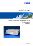
The Astro-Physics Command Center (APCC) Main Window
1.1
Features
Astro-Physics Command Center (APCC) is available in two versions, APCC Standard and APCC Pro.
Please review the feature list below regarding each version.
APCC Standard Features
Editable 3D telescope view shows the current orientation of your telescope.
Editable horizon tracking limits to stop tracking or park the mount once a horizon limit is reached.
© 2015 Astro-Physics, Inc.
Welcome to APCC
7
Editable meridian tracking limits to protect your telescope from pier collisions, and yet allow safe
tracking past the meridian.
Slew to counterweight-up positions with dynamic meridian delay feature (tied to meridian tracking
limits).
Safety slews for going into and out of counterweight-up positions. All declination movement occurs
while counterweight is safely pointing down.
Multiple virtual ports to allow easy connection of applications that do not require ASCOM support (like
PulseGuide or TheSky6/X).
Site management allows easily changeable setup for multiple sites.
Display and change time zone settings
Support for reading latitude/longitude/elevation from third-party GPS devices
GoTo/ReCal on RA/Dec and Alt/Az coordinates
Access to backlash, reticle, focus and PEM settings.
Set custom RA/Dec tracking rates
Can save/recall multiple RA/Dec and Alt/Az slew coordinates.
Park to editable alt/az position.
Available safety timer will cause the mount to park after a settable interval if a controlling computer
crashes or loses COMs.
Enables auto-park on power-down.
Easy to read status window summarizes mount status of critical parameters.
Logging of all commands for debugging if a problem occurs.
Convenient log zipper function to bundle relevant log files should problems occur and you need support
from AP’s world-class support team!
Can be configured to utilize a secondary serial port to prevent communication loss if a serial port to
USB converter fails
Terminal Interface tool to send commands directly to the mount.
All features of the latest GTOCP3 control box firmware are supported allowing feedback of the actual
status of the mount at all times.
Tight integration with the ASCOM driver.
Advanced support features for 3600GTO/3600GTOPE, 1600GTO and 1100GTO series mounts,
including Home recovery.
Includes the Horizons program for satellite, comet and asteroid tracking.
APCC Pro Features
Includes all features of the Standard version.
Dual-model pointing and tracking rate correction even with the telescope in the counterweight-up
© 2015 Astro-Physics, Inc.
8
Astro-Physics Command Center (APCC) Help File
position
Includes a separate application to acquire Pointing/Tracking model data (APPM).
1.2
Version History
Version 1.0.3.4 - 5/27/2015 (Release)
APCC - BUG FIX - releasing any of the Status View move buttons would trigger the Emergency Stop
window because the StopMove function used by the Emergency stop button was also used by the
mouse up events for all of the Status View's move buttons.
Version 1.0.3.3 - 5/27/2015 (Release Candidate)
APCC - Redesigned 3D Scope syncing logic to fix potential boundary conditions where the 3D scope
view might incorrectly show the mount's orientation.
APPM - Internal changes preparing for additional plate solving
Version 1.0.3.0 - 4/20/2015 (Beta)
APCC
* To prevent confusion on the use of the refraction checkboxes, they have been removed.
* Fixed display issues with the 3D Scope View
* Added "Create Virtual Ports First" option to Advanced settings, which when enabled will always create
the
virtual ports, even if the mount is off or not connected. This will allow the ASCOM driver to attach to a
virtual port
and potentially wait for the mount to be powered on.
* Fixed extra flip when scope is in a counterweight up position and the meridian limit set such that scope
should slew directly to the target position.
* Fixed similar to the above when meridian limits are set up.
* Fixed rounding error in longitude/latitude
* Park 2 and Park 3 used a hour angle of exactly -6, which caused some anomalies.
* Added additional commands for external programs to use:
? APCCVERSION returns Pro or Standard
? LIMITREACHED returns if a limit has been reached (Meridian or Horizon)
? SETTEMP/GETTEMP
? SETPRESSURE/GETPRESSURE
? SETHUMIDITY/GETHUMIDITY
APPM
Added missing DLL for AstroArt
Added new camera option to select SkyXPro Camera
Horizons
Allow "steps" to be used in calculations for fast moving satellites, like ISS
When clicking Stop tracking button tracking was completely stopped instead of returning to sidereal
Added option to display Native tracking rates.
Version 1.0.2.0 - 1/16/2015 (Release)
© 2015 Astro-Physics, Inc.
Welcome to APCC
9
APCC - BUG FIX - Fixed link in Horizons to APCC's help file.
APCC - BUG FIX - Set Meridian Delay to 0 before unparking.
APCC - BUG FIX - Fix excessive CPU utilization when "Automatic Shutdown" is selected.
APCC - BUG FIX - Improve some of ELS homing functionality.
Version 1.0.1.0 - 1/1/2015 (Beta)
APCC - Allow APCC to be connected to a COM Port waiting for mount to be turned on.
APCC - BUG FIX - Fixed "arithmetic overflow" that sometimes happened when calculating CRCs
Version 1.0.0.9 - 12/20/2014 (Release)
APCC - BUG FIX - Fixed start up issue with Windows XP.
APCC - BUG FIX - Fixed homing issue with 3600 mounts Homing feature.
Version 1.0.0.8 - 11/30/2014 (Beta 8-11)
APCC - BUG FIX - Fixed extra slew that was happening sometimes when slewing from Park 1.
APCC - BUG FIX - Main window's position should now be restored if the Save windows positions option
is set. Also, other window positions should be saved when closing the main window to exit APCC.
Previously the windows had to be closed first to be remembered.
APCC - BUG FIX - Not all COMM timeouts were being reported in the COM Timeouts window.
APCC - Improved detection of mount disconnects and reconnects. LST/RA/Dec/Alt/Az fields will now
flash when mount connection is lost.
APCC - Made improvements to logging.
Version 1.0.0.8 - 11/22/2014 (Beta 1-7)
APCC - Meridian Limits - Changed entry value precision to 2 decimal places.
APCC - Improved robustness of "Connect to Port" logic.
APCC - Improved the look and feel of the COM Port warning/error dialog. Removed pop-up warning
messages (replaced by aforementioned dialog).
APCC - Changed "Administrator" to "Elevated" to more accurately describe APCC's privilege level.
Implemented a different way to check for elevation.
APCC - BUG FIX - Main window's position should now be restored if the Save windows positions option
is set.
APCC - BUG FIX -Port status colors were sometimes incorrect.
APCC - Tweaked Park 1, 3, and 4's positions
APCC - Added "Always on top" option to Scope 3D View window.
© 2015 Astro-Physics, Inc.
10
Astro-Physics Command Center (APCC) Help File
APCC - BUG FIX - If the THUM service is running queries to the THUM would fail after 10 seconds but
would hold up APCC during that time so querying the THUM has been moved to a separate thread.
WARNING: users should NOT install and/or enable the THUM service/application software because then
APCC will not be able to communicate with the THUM.
APCC - BUG FIX - Added separate checks for updates for the Standard and Pro editions.
APCC - Added various information to the log files.
APPM - New Feature (Pro Only) - For dome users added new passive method for checking for dome
move completion. Instead of actively moving the dome via the ASCOM dome slewing commands, APPM
will assume that another program (e.g. DC3 dreams' ACP software) will issue the slew. APPM just
passively waits for the slew to complete. This option is setable via a new dome settings window in
APPM's settings menu.
Installer - Give permissions to "everyone" for Read/write access for logs and settings directories.
Version 1.0.0.7 (Official Release) - 10/12/2014
APCC - FEATURE - Added an option to the Log window to only show telescope move commands, which
can be useful for debugging autoguider issues.
Version 1.0.0.6 - 10/06/2014
APCC - Fixed issue with reading settings file.
Version 1.0.0.5 - 8/25/2014
APCC - Declination degrees was being set to 0 after a save if the field was a negative value.
APCC - Restored "West Limits" check box and finished implementing corresponding functionality (see
help section on Meridian Limits).
Version 1.0.0.4 - 8/15/2014
APCC - Now requires firmware version 'V" or later to run.
APCC - Changed out of date references to "U" firmware to save "V" firmware.
APCC/APPM - Further updates to the documentation .
Version 1.0.0.3 - 8/10/2014
APCC - BUG FIX - ASCOM driver would lock up if "Check for Valid Firmware" was clicked and the driver
was already setup to talk to APCC.
Version 1.0.0.2 - 8/8/2014
APPM - BUG FIX - Changing how Image FIT files were saved in an APPM run did not change
immediately (required a restart).
© 2015 Astro-Physics, Inc.
Welcome to APCC
11
APCC - BUG FIX - When "start with Status View Window" was selected and the Main window brought up
from the Status View, the Status View Window would minimize if the main window was minimized. Now
the Main Window will (only) Minimize and optionally hide itself if the appropriate settings are enabled.
APCC - BUG FIX - Clicking a button to show a window from the Status View would not show the window
if the window was previously opened but minimized.
APCC - BUG FIX - Horizon Limits check box was (purposely) cleared whenever parking or initializing the
mount. Now it is not cleared but not "armed" until the scope if first slewed into an area that is within the
horizon limits. Also, when clearing the Horizon limits trigger (which starts tracking) it won't actually be
armed again until the mount is again within the Horizon limits.
APCC - Made visible the "Correct for refraction" check box.
Version 1.0.0.1 - 7/16/2014
APPM - fixed bug reading Horizon limits from APCC's settings file.
Version 1.0.0.0 - 7/14/2014
APCC - added a triangulator class for future use.
APCC - automatically force the ASCOM driver to enable "chkAllowConnectIfMountNotPresent".
APCC - Updated the Help file with Howard's changes.
APPM - Improved performance of APPM when adjusting Point map and connected to APCC/Driver.
Version 0.99.99.73 (Release Candidate) - 6/25/2014
Minor changes to try to fix an issue found in RC72.
1.3
License Agreement
Astro-Physics, Inc. Software End-User License Agreement
This Astro-Physics, Inc. Software End-User License Agreement (“License Agreement”) must be read and
agreed to before you are authorized to install and utilize any of the following software products from AstroPhysics, Inc. (“Astro-Physics”): Astro-Physics Command Center Standard (“APCC-ST”), Astro-Physics
Command Center Pro (“APCC-PRO”), Astro-Physics Horizons (“APH”), and Astro-Physics Absolute Encoder
Utility (“APAE”). APCC-ST, APCC-PRO, APH and APAE are each referred to herein as either “Software” or a
“Software Product” and are collectively referred to herein as the “Software Products”.
IMPORTANT: This is a legal agreement between you (the Licensee) and Astro-Physics (the Licensor). By
installing, copying or otherwise using a Software Product, you are agreeing unconditionally to be bound by the
terms of this License Agreement. If you do not agree to the terms of this License Agreement, do not install or
use the Software Products.
For the purposes of this Agreement, "Software" or "Software Product" refers not only to the computer software
identified above, but also to all associated media, printed materials, "online" or electronic documentation,
including any and all executable files, tutorials, help files, utilities, and other files that accompany any of the
Software Products.
© 2015 Astro-Physics, Inc.
12
Astro-Physics Command Center (APCC) Help File
1.
License: Subject to the terms of this License Agreement, you are permitted to install and use the
Software on no more than two (2) computers per copy of the Software purchased, solely for your
personal and nonmilitary use, provided that only one (1) copy is in use at any given time. . You may
make one copy of the Software for archival purposes only, provided that you reproduce all copyright
or other proprietary notices that are on the original copy of the Software.
2.
Restrictions/Requirements:
a. APCC-ST, APCC-PRO, APH: These Software Products were written exclusively for mounts
manufactured by Astro-Physics or original equipment manufacturer (“OEM”) mounts that utilize
the GTOCP3 Servo Drive System (or a later version). Each of these Software Products may not
be used with any other mount or drive system. The firmware version of the GTOCP3 Control
Box must be version “V” or later.
b.
APAE: This Software Product was written exclusively for mounts manufactured by AstroPhysics that incorporate Absolute Encoders. It may not be used with any other mount or drive
system. For the duration that you own the associated mount, you may install this software on
any computer that you use to control the mount.
c.
APCC-ST, APCC-PRO, and APH: Astro-Physics grants to Customer a non-assignable, nontransferable license for these products, without the right to sublicense, to use the Licensed
Software.
d.
APAE: This Software Product may be transferred without charge along with the Astro-Physics
mount on which the Absolute Encoders are installed. You must provide Astro-Physics with the
name and address of the person to whom you are transferring the rights granted herein. The
recipient must provide a bill of sale and agree in writing to all terms of this License Agreement
in order to have the Software registered in their name.
e.
You may not disclose the license key provided by the Licensor for your use to a third party.
Such disclosure shall be considered a transfer of the Software itself and subject to the terms
and conditions contained herein regarding transfers.
f.
You may not bypass any facilities used by the Software to provide limited-time (trial/demo)
operation of the Software.
g.
You may not reverse engineer, decompile, disassemble, modify, alter, translate, or create
derivative works from the Software or make any attempt to discover the source code to the
Software Product.
h.
The Software may not be copied, redistributed, retransmitted, published, sold, rented, leased,
marketed, sublicensed or assigned other than as specifically permitted hereunder and
subject to the terms of this License Agreement.
3.
Title: The Software Product is owned by Astro-Physics and is protected by all applicable United
States copyright laws, international copyright treaties, and all other applicable national laws, rules
and regulations. Title, ownership rights, and intellectual property rights in and to the Software shall
remain with Astro-Physics. The Software Product is licensed, not sold. There is no transfer to you
of any title to or ownership of the Software, and this License Agreement shall not be construed as a
sale of any right in the Software.
4.
Termination: If you fail to comply with the terms of this Agreement, Astro-Physics may terminate
this License Agreement at its discretion. Upon termination, you must return or destroy all copies of
the Software, including all of its component parts. Your obligation to return or destroy all copies of
the Software upon termination shall not be deemed to restrict the rights of the Licensor and shall
be in addition to any and all other remedies available to Licensor.
© 2015 Astro-Physics, Inc.
Welcome to APCC
13
5.
Warranty Disclaimer: ASTRO-PHYSICS DOES NOT WARRANT THAT THE SOFTWARE WILL BE
DEFECT-FREE OR MEET YOUR REQUIREMENTS. THE SOFTWARE PRODUCT IS PROVIDED
“AS IS” WITHOUT WARRANTY OF ANY KIND, EITHER EXPRESSED OR IMPLIED, INCLUDING,
BUT NOT LIMITED TO, THE IMPLIED WARRANTIES OF MERCHANTABILITY, FITNESS FOR A
PARTICULAR PURPOSE AND NON-INFRINGEMENT.
6.
Limitation of Liability: IN NO EVENT SHALL ASTRO-PHYSICS, ITS OFFICERS, DIRECTORS,
EMPLOYEES, CONTRACTORS OR RESELLERS BE LIABLE TO YOU FOR DAMAGES, INCLUDING
ANY GENERAL, SPECIAL, INCIDENTAL OR CONSEQUENTIAL DAMAGES OF ANY KIND ARISING
OUT OF THE USE OR INABILITY TO USE THE SOFTWARE PRODUCT (INCLUDING BUT NOT
LIMITED TO LOSS OF DATA OR DATA BEING RENDERED INACCURATE, WORK STOPPAGE,
COMPUTER FAILURE OR MALFUNCTION, FAILURE OF THE SOFTWARE PRODUCT TO
OPERATE WITH ANY OTHER SOFTWARE PRODUCTS OR OTHER LOSSES SUSTAINED BY YOU
OR THIRD PARTIES), REGARDLESS IF THE LICENSOR HAS BEEN ADVISED OF THE
POSSIBILITY OF SUCH DAMAGE. SOME JURISDICTIONS DO NOT ALLOW THE EXLUSION OR
LIMIATION OF INCIDENTAL OR CONSEQUENTIAL DAMAGES, SO THIS EXLUSION AND
LIMITATION MAY NOT APPLY TO YOU. IN NO CASE SHALL ASTRO-PHYSICS LIABILITY, IF ANY,
EXCEED THE PURCHASE PRICE PAID BY LICENSEE FOR THE SOFTWARE PRODUCT.
7.
Export Laws: The Software Product and related technology are subject to U.S. export control laws
and may be subject to export or import regulations in other countries. You agree to strictly comply
with all such laws and regulations and acknowledge that you have the responsibility to obtain such
licenses to export, re-export or import as may be required.
8.
U.S. Government Licenses: The Software Product is a “commercial item” as that term is defined in
48 C.F.R. 2.101, consisting of “commercial computer software” and “commercial computer
software documentation” as such terms are used in 48 C.F.R. 12.212. Consistent with 48 C.F.R.
12.212 and 48 C.F.R. 227.7202-1 through 227.7202-4, all U.S. Government Licensees acquire the
Software with only those rights set forth therein.
9.
Jurisdiction: This License Agreement shall be governed by the laws of the State of Illinois,
excluding its conflict of laws principles. Each of the parties hereby consent to jurisdiction and
venue in the state and federal courts sitting in Winnebego County, Illinois. In any such dispute, the
prevailing party shall be entitled to recover its reasonable attorneys’ fees and expenses from the
other party in addition to any other remedy said party may be entitled. You may not assign or
transfer your rights or obligations arising under this License Agreement to any third party, and any
such attempted assignment or transfer shall be void and without effect. This License Agreement
may not be modified except upon mutual written agreement of the parties. The waiver by either
party of a breach of any provision of this License Agreement will not operate or be interpreted as a
waiver of any other or subsequent breach. If any provision of this License Agreement is deemed
unenforceable, such provision will be changed and interpreted to accomplish the objectives of
such provision to the greatest extent possible under applicable law and the remaining provisions
will continue in full force and effect. This License Agreement sets forth the entire understanding of
the parties and supersedes any and all prior oral and written agreements or understandings
between the parties regarding the subject matter of this License Agreement. Nothing contained in
any correspondence, purchase order, order confirmation form, invoice or similar documents
submitted by you to Astro-Physics or Astro-Physics’ distributors shall in any way modify or add to
the terms and conditions contained in this License Agreement.
I have read and agree to the terms of this License Agreement as set forth above.
Copyright ©2014 by Astro-Physics, Inc., 11250 Forest Hills Road, Machesney Park, IL 61115, U.S.A.
© 2015 Astro-Physics, Inc.
14
2
Astro-Physics Command Center (APCC) Help File
Getting Started
The information in this section will guide you through the APCC installation process and show you how
to set it up with the Virtual Port for the Astro-Physics V2 ASCOM driver.
Two detailed work flow sections have been prepared:
1. The first - Getting Started Work Flow - outlines the work flow for getting the program set up for your
system. The tasks in this section are performed when you first start using APCC, and are performed
much less frequently afterward.
2. The second work flow section - Operational Work Flow Basics - gives you an outline of the general
work flow you will use in your night to night astronomy endeavors.
To get the most from your observing session with APCC, be sure to review the Tips to Get the Most from
APCC.
In addition to this manual, there are some instructional videos at this link that you may find helpful.
2.1
Getting Started Work Flow
There are basically two work flow descriptions that should be helpful to you as you work with APCC.
First, you need to understand how to get the program set up to work with your mount, your observatory
and other software. This section provides a step-by-step outline of this work flow - but it is an outline.
Be sure to follow the more detailed steps in the next three sections to actually set up your system with
APCC. Later in this "Getting Started" section, we will provide the second section on operational work
flow. This will deal with suggested procedures and methods of operation in your normal night-to-night
observing and imaging after your system is all set up.
1. Get familiar with your mount. If you are new to Astro-Physics mounts, spend some time simply
using the mount with the keypad. Learn how your mount behaves. Become familiar with the
mechanics of the mount.
2. Make sure that you are familiar with the other software programs that you plan to use with APCC. If
you try to learn TheSkyX, Starry Night, MaxIm DL, CCDStack, ACP, CCDAutoPilot and APCC all at
the same time, you will probably be doomed to failure.
3. Become familiar with the AP V2 ASCOM Driver before you begin using APCC. Since most of the
software you will use with APCC will work through the AP V2 ASCOM Driver, it is best to first become
proficient with operations with the driver. If you have been using a program like TheSkyX with its native
driver, make the switch to using it with the AP V2 ASCOM Driver before combining it with APCC.
4. Confirm that you meet all of the Hardware/Software Requirements in the next section.
5. Follow the instructions in the section that follows to: Install APCC.
6. Start APCC and enter your license key information, if you have not already done so.
7. You will be prompted to enter your site information for your primary site. You can also enter
information for any other sites you wish at this time. For getting started, you only need the first site
you will use, so don't worry if you don't have the information for every site you will eventually enter.
You can add sites later.
8. Set up your Primary Virtual Port. DO NOT check the check box to Auto-connect to ASCOM driver on
first Virtual Port yet! You will do that AFTER the next two steps.
© 2015 Astro-Physics, Inc.
Getting Started
15
9. Set up the AP V2 ASCOM Driver.
10.In APCC's Connections Group Box, select your Primary COM Port to your PC, and then connect to
your mount.
11.Configure the rest of the Virtual Ports Tab for the way you plan to use your system. Many users will
only need the first Virtual Port for the AP V2 ASCOM Driver. Add extra virtual ports if you need them
(i.e. for a non-ASCOM app like PulseGuide), but don't add them unless you actually will use them.
NOW you can check the box to Auto-connect to ASCOM driver on first Virtual Port. Most users will
want to check both check boxes as shown here. Do not check the Auto-connect to ASCOM driver on
first Virtual Port if you plan to start APCC by connecting first with an ASCOM client. This is
explained further in the Virtual Ports Tab section.
12. Set your desired Park position in the Park Tab. Set the Unpark option in the dropdown list to Last
Parked. This is the normal Unpark setting for ALL permanent setups. If you are portable, and must
reestablish your position at each startup, set this to Park 4. If you just need to reestablish your
position this one time in a permanent setup, select Park 4 and then switch back to Last Parked once
pointing is established. To resume from Park 4, you will, of course, need to place the mount into the
Park 4 position.
13. Create your Horizon Tracking Limits if you will be using them.
14. Create your Meridian Tracking Limits if you will be using them.
15. If you have APCC Pro version, we recommend the following:
a. Establish your Horizon and Meridian Tracking Limits BEFORE doing anything in the Pointing Model
Tab.
b. If time permits, operate your mount normally for a few nights to be sure that you have everything
else working the way you want it to.
c. When you feel ready (or if you simply cannot wait), open the Pointing Model Tab, and then click on
the APPM button to get started with a pointing model.
If you follow these steps in order, you will have everything set up in a way that most users will find ideal.
There are, of course, many additional options and settings in APCC that you can work with, but start
with the basics and try to get a good understanding of the program before attempting to use the more
advanced features.
© 2015 Astro-Physics, Inc.
16
2.2
Astro-Physics Command Center (APCC) Help File
Hardware/Software Requirements
Mount Hardware Requirements:
o Astro-Physics GTO mounts, OEM German Equatorial mounts with GTO Servo System (Parallax
Instruments or Mathis Instruments).
o GTOCP3 Control Box with revision "V" or later firmware. Revision V began shipping with all mounts
starting at the end of July, 2014. Refer to this information from the Technical Support section of our
website. (http://www.astro-physics.com/tech_support/mounts/servo/cp3-chipupgrade.htm)
Minimum Recommended Computer Hardware Requirements:
The whole idea of "minimum computer requirements" for a single application is really no longer valid in
today's computer world. Any computer that can run any of the modern software packages that you will
be using with APCC will be adequate to run APCC. The issue in today's environment is whether your
computer can run ALL of the required software SIMULTANEOUSLY to achieve your desired goals.
APCC is unlikely to ever be run as a stand-alone piece of software. When you consider your computer
hardware, aim for a system that can handle all of the observing and imaging software that you plan to
use, and that can handle all of it running together. That being said, here are some general tips and
recommendations and a few specific requirements:
o RAM is generally more critical to adequate performance than processing power. If budgeting for a
computer system, spend the money on more RAM instead of the latest and fastest processors with
the most cores. 8GB of RAM is probably adequate for an imaging system, but 16GB or more is
even better.
o Solid State Drives (SSDs) have recently become much more affordable. They are certainly not a
requirement, but are recommended for your boot drive for their robustness, lack of moving parts, and
overall speed. At least 10GB of free drive space (for logs and settings) should be available.
o APCC makes some demands for graphics capabilities, but its demands are generally less than
those for either of the two most popular planetarium programs. If you can run TheSkyX or Starry
Night Pro Plus, you have probably already exceeded APCC's minimum requirements. However, for
clarity, please note the following:
3D accelerated graphics card or integrated controller recommended if using the 3D Telescope
View
OpenGL 1.5 or later required (Both planetarium programs mentioned above require higher Open
GL.)
o Native serial port, or installed PCI serial card, or USB/serial port converter required. For USB to
serial converters, we recommend the following:
Keyspan units (sold by Astro-Physics),
High quality units with FTDI chipsets (i.e. Industrial units from serialgear.com like their 2-port or
4-port),
© 2015 Astro-Physics, Inc.
Getting Started
17
Industrial USB to Serial converters from Moxa
Converters from Digi/Edgeport
We CAN NOT advise using ANY converter with a Prolific chip set!
Minimum Computer Software Requirements and Recommendations:
o Windows XP / Vista / 7 / 8 / 8.1
among OS choices.
32-bit or 64-bit Windows 7 Pro 64 bit is our current favorite
Required - Run Windows Update to apply all updates.
Required - You must have the .Net Framework 4.0 with all patches installed (Windows 7 and later
ships with .Net 4.0 installed). You can confirm that it is enabled in Control Panel => Programs
and Features => Turn Windows Features On or Off.
NOTE: .Net 3.5 is also required for some of the AP V2 ASCOM
Driver's features. Windows 8 and 8.1 do not ship with .Net 3.5
installed and you cannot directly download and install it. Please
see this link to enable .Net 3.5 on Windows 8 and later to have
full driver functionality:
http://msdn.microsoft.com/en-us/library/hh506443.aspx
o Required - The latest ASCOM Platform (currently 6.1 SP1) installed (http://www.ascomstandards.org)
o Required - The latest AP V2 ASCOM Driver (currently v5.06.00) installed (http://www.gralak.com/
apdriver)
o We recommend that you update your browser to the latest version
o We recommend that you install Adobe Acrobat Reader (may be needed to read APCC and ASCOM
PDF documentation)
Additional Requirement for APCC Pro's APPM Point Mapping Program:
o The FULL version of DC3 Dreams PinPoint application v5 or later (v6 is highly recommended).
2.3
Installation and Licensing
Preparation
In order to install and run APCC, please ensure following:
1. Make sure that you meet ALL of the requirements in the Hardware/Software Requirements section as
described earlier in the Welcome to APCC.
2. You must register a specific e-mail address with Astro-Physics for APCC. This will be the official e-
© 2015 Astro-Physics, Inc.
18
Astro-Physics Command Center (APCC) Help File
mail address that is associated with your license. This is required to obtain a trial license key or
make a purchase.
3. Download the program from this APCC Download Link
Installation
To install the program, double click on the APCC_Setup_1.x.x.exe or the APCC_Pro_Setup_1.x.x.exe
file that you have downloaded. Follow the instructions on the installer. You may need to disable some
anti-virus or firewall software before installing. You should NOT need to "Run as Administrator."
However, YOU must have administrator privileges for your current logon. These are not the same thing.
Obtaining a license key
When you run APCC for the first time and until you enter a license key you will be presented with the
Trial Registration Information Dialog when APCC starts.
© 2015 Astro-Physics, Inc.
Getting Started
19
Confirming you have the proper firmware
If you are not sure that your mount has the proper firmware installed then you can check it by clicking
Check for Valid Firmware. For this to work, you must have the AP V2 ASCOM Driver installed and
configured for normal (pre-APCC) operation. The serial cable must be connected from the computer to
the mount, and the mount must be powered on. If you can successfully use the Check Port button in
the AP V2 ASCOM Driver's Telescope Setup window, then you are set up correctly for this test.
If you don't have the correct firmware installed for this mount, you can click the Order Firmware button
for more information on how to obtain it.
Obtaining a trial license key if your computer has internet access
You can try APCC for up to 30-days before purchasing. To do so you will need to make sure your e-mail
is authorized to receive a trial license key. Authorization is required to ensure that you have the correct
firmware and control box, which will help minimize support questions.
To get an authorized e-mail you should contact Astro-Physics via phone or e-mail (support at AstroPhysics dot com) requesting that your e-mail be authorized for the trial. In order to be authorized, you
will have to purchase the upgraded firmware (revision "V" or later) if you do not already have this firmware
installed in your GTOCP3. Mach1GTO, 1100GTO and 1600GTO mounts shipped beginning July 22,
2014 and later will have the upgraded firmware. Owners of these more recent mounts must still get an email address authorized for the licensing process.
Once your e-mail address has been authorized, enter your Name and E-mail address (twice) and click
the Get Trial Key (Via Internet) button. Make sure that you run APCC on the computer you intend to
run it from.
You should receive an e-mail within a few minutes with your trial license key. Just copy and paste all 5
lines of the license key into the text box at the bottom of the window. If successful, the window will now
tell you that you have 30 days remaining in your trial. This window will come up every time you start
APCC so you'll know how many days remaining you have.
To begin using APCC click Start APCC.
© 2015 Astro-Physics, Inc.
20
Astro-Physics Command Center (APCC) Help File
Clicking the PURCHASE LICENSE button will take you to the Astro-Physics e-commerce page for
APCC. From there, you can click the appropriate Buy now ! button for the version you wish to
purchase. Follow the instructions to complete the purchase. Upon completion of the purchase, you will
be sent an e-mail with your full license key. Enter it in the same manner as the trial license described
above. If you are really smart, a successful registration of a full license will give a message like the
following:
© 2015 Astro-Physics, Inc.
Getting Started
21
Obtaining a trial license key if your computer does not have internet access
If the computer on which you intend to use APCC does not have internet access you can click the Get
Trial Key (Manually) button. A window like below will appear:
© 2015 Astro-Physics, Inc.
22
Astro-Physics Command Center (APCC) Help File
Write down the number and from a computer with internet access e-mail it to Astro-Physics. The staff of
Astro-Physics will manually generate the license key for you and send via a return e-mail. This could
take 2-3 days since the license key won't be generated over the weekend or holidays.
After you have entered the license key information, select the Start APCC button.
Clearing the license key
If for some reason you need to reenter your license key you can click the Clear License Key button.
You will then be able to enter a new trial license key the next time you start APCC.
2.4
Setting up your primary Virtual Port
What is a virtual port? Real serial ports are single, unique point to point communication contacts
between two, and ONLY two devices. Serial ports, by their nature cannot be shared. Virtual serial ports
are software-based rather than physical. Through the Virtual port software, you can effectively create
multiple ports that can all be merged into a single entity that can then communicate as a single device to
your GTOCP3 servo control box. APCC can create up to four of these virtual ports. The primary port is
normally used for the AP V2 ASCOM Driver.
To integrate the AP V2 ASCOM Driver into APCC for seamless operation, you will need to first set up
your primary Virtual Port in APCC. This only takes a few moments.
1. Decide on Port Numbers. Your first task is to determine which ports are already in use on your
computer, and to make a good guess at which additional ports may be added. You will certainly have
a port reserved for APCC, and you may have additional ports reserved for such things as a focuser,
rotator, dew heater controller, weather station, smart UPS or other serial devices. Remember that at
setup, you may not have all of these devices connected, and that they therefore may not show up on
your system. Use Windows Device Manager to see your current COM Ports. If you use Keyspan
USB to Serial converters, the Keyspan Serial Assistant will show you all of the currently connected
converters and their assigned port numbers.
As a general rule, most people will reserve port #s 1 through 10 for normal "real" ports, whether native
© 2015 Astro-Physics, Inc.
Getting Started
23
or via a USB to serial converter like the Keyspan units. COM 11 is often a good place to start with
your primary virtual port.
2. Open APCC, if it is not still open from your installation. You do not need to be connected to the
mount.
3. Click on the Virtual Ports tab in APCC.
4. Click on the Port Selection Dropdown list for the first (top) virtual port. The default is "None", but all of
the available choices will be listed.
5. Select the COM Port that you decided on in step #1 from the dropdown list
6. YOU MUST click the "Create" button to create the port in your system! This isn't simply an
APCC option, but goes to the heart of the PC's operating system.
© 2015 Astro-Physics, Inc.
24
Astro-Physics Command Center (APCC) Help File
7. DO NOT check the checkbox to Auto-Connect to the ASCOM driver on the first Virtual Port yet!
8. Remember the COM port number you just created, and proceed to the next step in these instructions:
Setting up the AP V2 ASCOM Driver
9. More information on using the Virtual Ports can be found under the Main Window => Virtual Ports Tab.
2.5
Setting up the AP V2 ASCOM Driver
Make sure you have v5.06.00 or later of the AP V2 ASCOM driver installed. We encourage you to check
the AP V2 ASCOM website frequently for updates: http://www.gralak.com/apdriver in addition to making
sure that you have the most recent version of APCC installed.
1. In the ASCOM Driver's Telescope Setup; check the APCC Virtual Port option check-box.
2. Make sure that the port number selected matches the top port in APCC's virtual ports.
3. Increase the Timeout to 1000, 2000, or even 3000 ms if you experience issues when starting directly
from ASCOM client software. 2000 is probably a good place to start. If using the driver by itself
without APCC, I would normally use a much shorter timeout value – maybe 200 to 500ms. However,
since APCC is in primary control of the mount, the AP driver may need to wait at times for APCC to
do its job before responding. This is especially true at startup where a whole lot of serial traffic is
happening all at once. This way, the driver will give APCC time to get the virtual ports started and
initialization completed.
4. Set the Retry Count to 0.
5. The Use ASCOM Serial Object option check-box is checked by default. If you experience
communication problems, try unchecking it, and then a C++ COMs library will be used. In particular,
be aware that one or the other may work better during shutdown and/or startup. This preference
seems to vary with different computers and USB to serial devices.
See the picture below:
© 2015 Astro-Physics, Inc.
Getting Started
25
6. When everything is set, you can use the "Check Port" button if you are connected to the mount with
APCC. The mount MUST be powered up and connected to APCC for this button to work! You can
always check this later. A successful connection will open a small window that says: Mount Found!
Firmware V. A failure will result in a small window that says: Mount NOT Found!
© 2015 Astro-Physics, Inc.
26
Astro-Physics Command Center (APCC) Help File
7. Open the expanded Advanced section of the AP V2 ASCOM Driver's Setup window by clicking the
button in the lower right corner.
8. At the bottom of the Initialization Setup pane is a checkbox to "Allow connect if mount not present".
Most users will want to check this box. It will allow APCC the extra time that may be required
to complete initialization of the mount without causing a timeout in the driver.
© 2015 Astro-Physics, Inc.
Getting Started
27
You now have your AP V2 ASCOM Driver and your APCC Virtual Ports configured to work together.
Additional details and options can be found in the section on the Virtual Ports Tab under the Main
Window, and in the documentation for the AP ASCOM V2 Driver.
2.6
Operational Work Flow Basics
Introduction
The earlier section on Getting Started Work Flow was designed to help you get the system up and
running. This section will guide you through normal operations as you use APCC with other software to
achieve your observing or imaging goals. The steps below are not hard and fast rules. They are guides
that, if followed, will present the easiest and most trouble-free way of operating your system as a whole.
© 2015 Astro-Physics, Inc.
28
Astro-Physics Command Center (APCC) Help File
Use the AP V2 ASCOM Driver!
First off, the question often arises: If I have a choice between using an external program's native driver
(as in TheSkyX), or connecting the software through the AP V2 ASCOM Driver, which should I choose?
We strongly advise using the AP V2 ASCOM Driver! Here are some reasons:
1. The AP V2 ASCOM Driver is a full fledged hub. It will accommodate a very large number of programs
all connected at the same time, and will do so without any problems. As a single hub, the driver will
minimize the serial traffic between the software and the mount by eliminating redundancy.
2. The AP V2 ASCOM Driver takes advantage of the full set of Astro-Physics servo commands, many of
which were developed specifically for either the driver or for APCC. Since these new commands are
not being published, the native drivers found in other software will be limited to the older set of
published commands.
3. The AP V2 ASCOM Driver can create log files for troubleshooting any issues that you may have.
4. We can provide a certain amount of support if you encounter issues with a program that uses the AP
V2 ASCOM Driver. We, of course, cannot fix a problem that is in someone else's software, but we
may be able to figure out what is happening to cause the problem. If you use a native driver, you will
be limited to the support that the software provider can give you. We can't support someone else's
driver.
Order of Operations
While there are several ways that you can start up and run your system, we recommend the following
order of operations:
1. Power up your imaging camera(s) and software and start the cooler(s). This is simply a time
saver. The cameras might as well be cooling while the rest of the system is being activated.
2. Power up your mount. Since APCC automatically sets the Auto-Park feature in the servo, the
mount will not start default sidereal tracking, even if it was not properly shut down at the end of the
previous session. The mount will quietly wait in place until it is initialized and unparked by APCC with
NO loss of pointing accuracy.
3. Start APCC. If you have checked the boxes in the Virtual Ports Tab as described in the Getting
Started Work Flow section, APCC will connect automatically to the mount and initialize it. It will then
create all of the virtual ports that you have defined. Finally, it will start up the AP V2 ASCOM Driver
and connect to it through the first virtual port .
4. Connect the imaging software to the mount if you normally do that. This was added as a
separate instruction because we advised you to start your imaging software earlier to cool the camera
and we don't want you to forget.
5. Start and connect other software. Start up each additional piece of software that you will be using
and connect that software to the mount, and to any other relevant devices. Refer to the other software
and hardware documentation for advice on the order in which you power other devices like focusers
and start the various other programs.
6. DO YOUR ASTRO-THING!
Note: Many of you with remote operations will have a scripting program like ACP or CCD Auto-Pilot that
© 2015 Astro-Physics, Inc.
Getting Started
29
will do this for you. If this is the case, we still recommend this basic sequence except that the first thing
activated will be the scripting software. Your scripts should include sufficient time (waits) for each
element to be completed before proceeding to the next.
Shutdown
The shutdown sequence is very much the reverse of the Order of Operations listed above with a couple
exceptions. Here is the recommended sequence:
1. Start the imager's cooler warm-up. Again, this is listed first as a time saver. For cameras that
require a warm-up, this might as well be going on while the rest of the shutdown is taking place.
2. Park the mount. Most of you will choose to park the mount to a predefined park position, even
though this is not strictly necessary with an Astro-Physics mount. For many, the park position is
dictated by the observatory architecture, or by the positioning of a flat screen. See the Park Tab
section for more details. If you are using TheSkyX to park the mount, be sure to see the special note!
3. Disconnect the imaging software from the mount. Once more, we provide this as a separate
instruction so that it is not forgotten. Since the warm-up of the cooler can take a while, the imaging
software is often the last piece of software to be closed down before shutting off the computer. You
will want to disconnect the imaging software from the mount before closing APCC.
4. Disconnect and shut down other software. Disconnect each piece of software from the mount
and any other devices that it controls, and then shut that piece of software down.
5. Verify that everything is disconnected. There are 2 steps to this:
a. If you have connected to the mount with one or more NON-ASCOM programs, go to the Virtual
Ports tab and make sure that the only active virtual port is the top one (the AP V2 ASCOM Driver's
port). You do not need to delete the other ports that you may have. Just make sure that no further
data is being transmitted or received over the lower three virtual ports. If you only connect to the
mount through ASCOM clients, you can skip this step.
b. The AP V2 ASCOM Driver has an indicator at the top of the Handbox Window that tells you how
many clients are connected. (See the AP V2 ASCOM Driver's help file.)
The first value (in the above case a 1 ) tells you how many client programs are still connected to the
mount. The second value tells you how many DC synchronous focusers are connected. (Note:
Digital focusers and focusers requiring drivers cannot use the simple AP focus controls and are
© 2015 Astro-Physics, Inc.
30
Astro-Physics Command Center (APCC) Help File
NOT included in this count. For most of you, the second value will always be a zero.) When the
client count gets down to 1, all the programs have been disconnected. The remaining 1 is APCC.
If you have chosen the Auto-Shutdown feature in the Advanced Settings window, the shutdown
timer will start when the last client apart from APCC is disconnected.
6. Close APCC. If you did not choose Auto-Shutdown as mentioned above, close APCC in one of the
conventional ways. When APCC closes, it will also close the last instance of the AP V2 ASCOM
Driver. APCC and the driver should be shut down before proceeding to the next step.
7. Power off the mount.
8. Finish closing down your imager and shut down the observatory.
2.7
Tips to Get the Most from APCC
Using the Help Files and Manual
We have tried to make this information as complete and well organized as possible. If you have
suggestions for improving the documentation, please let us know!
This information is available in many formats to suit your situation. We encourage you to refer to these
help files first before posting to the forum or calling for support. Please let us know how we can improve
the information or presentation to make it easier for all to use.
Help icons - The Help icons available throughout APCC are likely to be the most handy method for
gaining access to information when you need it. Each icon links to the specific part of this manual that
explains the feature or function. This puts pertinent information at your fingertips for immediate
reference. There are frequent links to other information for further clarification.
APCC Toolbar - The APCC toolbar includes a Help selection that will open the entire manual for your
review in html format. This version includes a search function and allows you to designate sections of
the manual as favorites for quick reference at a later date.
Adobe PDF - If you plan to review the manual at times when APCC is not active, the cross-platform
PDF format will be handy. Download it to your computer, print it for reference or upload it to your
portable device. If you use it in conjunction with an App like iAnnotate, you can highlight information
that you want to remember or make additional notes for future reference.
Apple iBooks (ePub format) - This handy version can sit on the bookshelf on your iPad or even your
iPhone! Naturally, other e-readers in ePub format can be used, as well.
We will make an effort to keep the screen shots updated as minor changes occur in upcoming releases,
however you may find some outdated screen shots that look slightly different. Please bear with minor
differences. However, if you find screen shots that are confusing and require immediate updating, please
let us know.
Instructional Videos
We have prepared some instructional videos at this link. The instructional videos are a work-in-progress,
and will be continuously updated and improved over time. Please note that some of the videos are
already a bit dated and may show screen shots that are no longer current. The basic information
contained in the videos, however, should still all be correct.
© 2015 Astro-Physics, Inc.
Getting Started
31
Help ? in Corner of Group Boxes
In the upper right corner of almost every group box in APCC you'll find a round button with a "?". Clicking
this button will open the help for the group box.
Tabs
Tabs provide a quick means to access key areas of the program. You can rearrange the order of the tabs
to suit your needs, however the order will not be saved for the next session at this time.
All tabs are visible for all mounts and all versions of APCC with the following exceptions:
Pointing Model Tab: Only visible for the APCC Pro version.
ELS Tab: Only visible for 3600GTO
AE Tab: Only visible for 1100GTO and 1600GTO (Not currently available in the first APCC release.
Use the APAE Utility instead.)
Group Boxes
Closely related items are subdivided into Group Boxes enclosed within a yellow box and given a title to
describe their relationship. Some of the group boxes, like the Move Scope group box shown below are
always visible on the Main Window. Others are organized within the various tabs or windows.
Resizing Windows
For your convenience, the various windows can be resized to suit your needs. Simply grab the lower right
corner of the window (or the sides) and move it to fit the desired space. Note that the text and graphics
will adjust proportionally to the width or length that you specify. This will allow you to optimize the
monitor placement of all of the programs you typically use to enhance your work flow.
When you resize APCC, the controls will scale as well. The scaling of controls and fonts is not always
perfect but is usually good enough for most purposes. For instance, you can maximize APCC so that
the controls are easily visible from a distance, or shrink APCC so that other Windows are also visible.
© 2015 Astro-Physics, Inc.
32
Astro-Physics Command Center (APCC) Help File
If you wish to save the location of the windows when you exit APCC, refer to Settings Menu. Please refer
to Known Issues if you are using Windows XP or Vista.
Limit Primary Control of Your Mount to One Input Device
Your mount can be controlled by a variety of input devices, including the Keypad, iPad/iPhone or
computer. Although the devices can work together very well to command the movement of your mount,
we recommend that you use only one in your session and that you always initialize, unpark and park
with the same primary control device. We expect that for most of you, the primary control device will be
your PC with APCC. Remove the primary control functions from any other device that you use. For the
keypad, this means setting the auto-connect to EXT. Other devices like iPads should have the timeupdating functions to the mount disabled, and should not be used during your final park and shutdown
routine.
Remember these rules:
ONLY ReCal from the same device that sent the slew command.
NEVER perform a full SYNC from a secondary device!!!
This document provides information regarding various options for controlling your mount: Control Options
for Astro-Physics Mounts
3
Initialization Window
Whenever APCC detects that the mount needs to be initialized (right ascension = 0 and declination =
90), the Initialize Astro-Physics Mount window will open. By default, if you do nothing, whatever
parameters have been set up in this dialog window will execute in a user-defined number of seconds.
(Default is 10 sec. See the Advanced Settings section under Main Window => Setup Tab) However,
you can stop this auto-initialization by clicking the button Stop Auto-Init. This will allow you to check
your settings and change them, if you wish.
© 2015 Astro-Physics, Inc.
Initialization Window
33
IMPORTANT: This window will NOT appear if you have already initialized the mount with another source,
like the keypad. Also bear in mind that the mount remains initialized until it is power cycled. Remote
observatories that leave power on to the mount (not recommended for safety reasons) will maintain an
initialized state in the mount and will also not see this window upon startup of APCC.
At any time, you can access this window under the Settings Menu to adjust the settings. BE
CAREFUL!!! Re-initializing an already initialized mount with new information can result in changes to the
mount's knowledge of where it is pointed.
© 2015 Astro-Physics, Inc.
34
Astro-Physics Command Center (APCC) Help File
Initialization
Select Site: Selects the site that will be used to initialize the mount. APCC will use the site's latitude,
longitude, time zone, elevation, default temperature and pressure. To edit or create new sites, click the
Manage Sites button.
Manage Sites: Click this button to bring up the Manage Sites Dialog.
Unpark from: This selects the park position from which APCC will unpark. Usually you will want to
select "Last Parked." This is true even if you park to a defined park position. The only time you
would normally unpark from a defined position is of you are setting up the mount or if you have moved the
mount via the clutches. Note that you can also select Don't Unpark from the drop-down list in case you
don't want to unpark when initializing. Refer to the Park 1, 2, 3 and 4 Positions Defined section if you are
unsure of the various options.
© 2015 Astro-Physics, Inc.
Initialization Window
35
Unpark Now: Clicking this button will allow you to unpark the mount from one of the Park positions. You
cannot use this button if you have Last Park ed selected. You typically would use this button to unpark
after you have physically moved the telescope to one of the Park positions. Refer to the Park 1, 2, 3 and
4 Positions Defined section if you are unsure of the various options.
Optional Initialization
A basic initialization will give the mount the necessary information to calculate its position (time and
location data) and will unpark the mount to either its calculated pointing position, or to a user selected
pre-defined Park position. You may, however, wish to set other operating parameters as part of your
general start-up / initialization process. These other parameters can be set automatically at initialization
by checking the boxes and selecting the values in the options listed below. Note that the AP V2
ASCOM driver, the keypad, or any other software can set its own parameters which can override the
parameters you set here at initialization. The GTO Servo will always act on the last parameter that it
received for any given option below.
Set Tracking Rate: If this option is checked, the selected tracking rate is sent to the mount. If this
option is not checked, the mount will begin tracking at the default sidereal rate.
Set Guide Rate: If this option is checked, the selected guide rate is sent to the mount. If this option
is not checked, the default guider rate of 1x will be used.
Set Move Button Rate: If this option is checked, the selected rate will be used for button presses
within APCC. If this option is not checked, the default rate of 600x will be used. Note that direction
buttons in the keypad and in other software will generally override this rate to whatever rate is in that
particular device or software. That rate will remain until APCC or another device changes it again.
Set GoTo Slew Rate: If this option is checked, the selected slew rate will be used for slews from
within APCC. If this option is not checked, the default slew rate of 1200x (600x for the 3600GTO) will
be used.
Set Dec Backlash: If this option is checked, the backlash value is sent to the mount. If this option is
not checked, the default is zero. Remember that backlash settings are generally NOT recommended
for most users, and are DEFINITELY NOT recommended if you are autoguiding. They are generally
useful only for visual observing or manual guiding with a crosshair eyepiece.
Set RA Backlash: If this option is checked, the backlash value is sent to the mount. If this option is
not checked, the default is zero. Remember that backlash settings are generally NOT recommended
for most users, and are DEFINITELY NOT recommended if you are autoguiding. They are generally
useful only for visual observing or manual guiding with a crosshair eyepiece.
Set PEM: If this option is checked, periodic error correction can be forcibly enabled or disabled during
initialization. If this option is not checked, PEM will remain disabled.
Command buttons
Stop Auto-Init: Stops the auto-initialization process. This button is not present in the Initialization
window accessed through Settings since it is not needed there.
© 2015 Astro-Physics, Inc.
36
Astro-Physics Command Center (APCC) Help File
Initialize: Clicking this button will initialize the mount with whatever parameters you have defined above.
If you have stopped the Auto-Initialization to make changes to your settings, this will then complete the
initialization process. The rates on the Rate Settings tab will update.
Cancel: Clicking this button will cancel the initialization and any changes you have made to the settings
will not be saved. You may wish to do this if you will be initializing later after downloading new GPS site
information.
4
Status View Window
The Status View Window provides a convenient way to view information regarding your mount's position,
rates, time and other information all in one window. You can initiate button rate commands to center an
object in your eyepiece or initiate a "stop" command in an emergency. It also provides a quick link back
to to other windows. The Status View Window can be resized to fit your screen.
© 2015 Astro-Physics, Inc.
Status View Window
37
Opening the Status View Window
Show Status View Window When Starting: If you want the Status View Window to display instead of
the Main Window each time you start APCC, check the appropriate box on the Setup Tab of the Main
Window.
Status Window Button: Click on the button located on the Main Window under the Telescope Position
group box.
Quick Access Controls
© 2015 Astro-Physics, Inc.
38
Astro-Physics Command Center (APCC) Help File
Connect to Port/Disconnect Port: To connect APCC to your mount, press this button. Note that if an
ASCOM application invokes the driver and the driver cannot connect to APCC on its virtual port then the
driver will try to start a new instance of APCC and wait until the connection has been established. On
the Virtual Ports tab you will want to have "Auto-connect COM port and create virtual ports when started"
checked. Refer to Connection Group Box for more information.
Park: Parks the mount to the park position selected on the Park Tab.
EMERGENCY STOP!: Press this button to stop the mount.
Tracking Rate: The symbols represent various tracking rates. The yellow line above the symbol
indicates which rate is active. You can change the rate by selecting the appropriate symbol, with the
exception of the variable rate. This rate must be set on the Rate Settings Tab.
NOTE: You can move the scope with the move buttons and the rate will still be maintained. Doing a slew
usually means you want to look at a different target so track ing is reset to sidereal because almost
every other target's track ing rate is sidereal!
N/S/E/W/NE/NW/SE/SW: When pressed, the mount will move in the direction that the button indicates.
The rate of movement will be defined by the number in the center box, which shows the rate the mount
moves in sidereal rate units when the button is pressed. This number can be changed with the arrows or
simply type the value in the field.
Swap N/S: Swaps the direction of North and South button commands.
Swap E/W: Swaps the direction of the East and West button commands.
Buttons for quick link to other windows: Any of the remaining eight buttons at the far right can be
clicked to open the corresponding tab or window.
Mount Position
Displays information obtained from the mount control box.
© 2015 Astro-Physics, Inc.
Status View Window
Rates
Displays information obtained from the mount control box.
Time
Displays information obtained from the mount control box.
Other
Displays information obtained from the mount control box.
© 2015 Astro-Physics, Inc.
39
40
Astro-Physics Command Center (APCC) Help File
Faults: This field can display the following:
None = No faults
Power = Low Power fault
Stall = Motor Stall
Servo = Servo fault
If there are multiple items they will have a "+" sign between them. For Instance: "Power+Stall".
5
Main Window
The Main Window was designed so that you can monitor the most important connection, telescope
position and status information at all times, regardless of which tab is open. The controls for moving the
scope via the buttons are also handy.
The tab format allows you to easily access all settings throughout your settings.
© 2015 Astro-Physics, Inc.
Main Window
5.1
41
Connection Group Box
In this group box you can set up the COM port and the timeout to the COM port.
Primary COM Port: The list of serial ports that were detected on the computer will be displayed in this
drop down list box. Select the default COM port that APCC will use when the Connect to Port button is
pressed. If you have a GTOCP3, you want this port to be the one connected to the top RS-232 port on
© 2015 Astro-Physics, Inc.
42
Astro-Physics Command Center (APCC) Help File
the GTOCP3 control box.
For 1600GTO and 1100GTO owners with the optional Absolute Encoders (and the GTOAE box), there
are two options. If you will NOT be using your keypad, use the port that connects through the Keypad
receptacle of the GTOCP3. If you wish to have the keypad available for use, then connect APCC directly
to the GTOAE box. If you find at some point during your session that you need to use the APAE
Utility, simply disconnect APCC by clicking the button as described below. Use the APAE Utility, and
when you are finished, close it down and then reconnect with APCC.
Note that to complete your configuration you will need to set up at least one virtual COM port through
which the ASCOM driver can communicate to APCC and the mount. See Setting up your primary Virtual
Port for more details. Additional information can be found in the Virtual Ports Tab section.
Backup COM Port: If you choose to, you can select a secondary COM port for APCC to try if the
primary COM port has a problem for any reason. To use this feature you will need to use both ports on
the control box and will need a second USB/serial port converter. This adds an extra layer of reliability in
case the primary USB/serial port converter fails. The backup port will be the bottom COM port of the
GTOCP3 control box. Ideally, this should be a physically separate serial port from the primary port. If
you simply use another port on a single multi-port USB to serial converter, and the converter or USB
connection fails, you will lose both ports and gain nothing. If you use a second USB to serial converter
that is attached to a different USB port on the computer, you are much more likely to survive a COMs
problem.
Timeout: Here you can set the timeout in milliseconds for responses from the mount. Usually 100 or
200 ms is good enough. However, sometimes it may be necessary to increase this value to 300, 400 or
even 500 ms. (Note the difference between this recommended setting and the longer recommendation for
the AP V2 ASCOM Driver when it is used through APCC's Virtual Ports.)
Connect to Port/Disconnect Port: To connect APCC to your mount, press this button. Note that if an
ASCOM application invokes the driver and the driver cannot connect to APCC on its virtual port then the
driver will try to start a new instance of APCC and wait until the connection has been established. On
the Virtual Ports tab you will want to have "Auto-connect COM port and create virtual ports when started"
checked.
Refresh Ports Button: As its name implies, clicking this button will refresh the list of COM ports
available on the PC. The updated list will then appear in the COM port selection drop-downs.
COM Events Button: This button enables when there have been communications errors like timeouts, or
servo errors like low power or motor stall. Clicking the button will open a viewer to the list of errors. For
the 1100, 1600, and 3600 mounts a $V# command timeout might get registered as a COM event. This is
normal and it can be ignored. That command is simply being sent to try to determine if the AE box is
present.
© 2015 Astro-Physics, Inc.
Main Window
43
Click the Clear Errors button to clear the screen. When you close the window, the COM Events button
will be grayed out again.
5.2
Move Scope Group Box
Controls to move the mount are in this group box. You can select the move button rate and also swap
North-South and East-West directions. When you press and hold a button, RA Delta will display the
approximate movement of the mount. When you let go of the button, the calculations will continue to be
updated as polls to the mount are completed.
N/S/E/W/NE/NW/SE/SW: When pressed, the mount will move in the direction that the button indicates.
The rate of movement will be defined in the Move Button Rate drop-down combo box.
STOP: Stops any mount movement initiated by a button press. This might be necessary if the serial port
command gets corrupted or doesn't make it to the control box. Usually tapping one of the direction
buttons will stop movement as well because a quit move command is always sent when a button is
released.
© 2015 Astro-Physics, Inc.
44
Astro-Physics Command Center (APCC) Help File
Move Button Rate: Select the rate that will be applied when you press one of the directional move
buttons.
Swap N/S: Reverses the direction of North and South button commands. This is useful to adjust the
action of the button pushes to make them more intuitive and instinctual. For instance, if the star moves
down when you push the “N” button, click on the Swap N/S button. Now, the star will move up when you
push the "N" button, which will make subsequent adjustments easier. You can make the same
adjustment with the “E” and “W” buttons. When properly set up, the direction buttons will cause the
object to move according to your orientation.
Swap E/W: Reverses the direction of the East and West button commands. Refer to the Swap N/S
section above.
IMPORTANT NOTE:
The background color of Swap N/S and/or Swap E/W will turn
yellow if APCC detects that the mount has the direction
reversed. When reversed this can cause autoguider calibration
failures so it should NOT be left this way if you are attempting to
do imaging.
Auto-fix N/S/E/W Movements: When checked APCC will monitor and correct the mount direction if
reversed. If you plan to autoguide through the AP V2 ASCOM Driver it is recommended that you keep
this checked. It is important to understand that the direction buttons can NOT be swapped if this box is
checked. This includes attempts to swap directions from the AP V2 ASCOM Driver and the keypad. If
you wish to do some manual movements with the direction swaps in effect, temporarily uncheck this
box, and then recheck it when you are ready to start imaging. It is important for calibration and guiding
to all be done with the direction moves in their normal state.
RA Delta/Dec Delta: Shows the approximate amount of movement since the start of the last button
press.
Clear: Clears the RA and DEC Delta values.
5.3
Telescope Position Group Box
This box shows all of the position information for the mount.
© 2015 Astro-Physics, Inc.
Main Window
45
When APCC is connected to the mount, the scope's position is shown by a red square in the virtual Sky
window view. The pier side is shown in the upper left and right with either an E or W within a yellow box.
The 3-D telescope view can be opened by clicking the 3D View button.
When slewing, the word SLEW will flash in the bottom left of this window.
LST: This shows the current local sidereal time. Clicking the LST text will swap to show the hour angle
(HA), which is the time distance of the scope from the Meridian. You may have noticed that there is no
way to enter your clock time. APCC uses your computer time when sending time information to the
mount. You may wish to utilize time server software to keep your computer time as accurate as
possible, if that is important to your operation.
RA: This shows the right ascension position of the mount.
DEC: This shows declination position of the mount.
ALT: This shows the altitude position of the mount.
AZ: This shows the azimuth position of the mount.
5.4
Status Bar
The status bar is always visible at the very bottom of the main window.
The Status Bar provides the following information:
Park State: Valid states include Unparked, Parked, Parking, and Unparked (AP). The last state
indicates that the mount will auto-park if power is removed and the mount is not "officially" parked.
RA Tracking State: Valid states include Stopped, Sidereal, Lunar, Solar, and Custom.
Guide Rate State: Valid rates include 0.25x, 0.50x, and 1.00x.
PEM State: Valid states include On, Off, Recording, Encoder
RA Tracking Rate State: Rate in arc seconds per second. There will only be values here if you have
set a custom rate, or are set to the Lunar or Solar rate. Otherwise, the rate will show as zeros if you
are set to sidereal.
Dec Tracking Rate State: The rate in arc seconds per second. There will only be values here if you
have set a custom rate. Otherwise, the rate will show as zeros.
All of the above values are polled from the mount every few seconds.
© 2015 Astro-Physics, Inc.
46
Astro-Physics Command Center (APCC) Help File
5.5
Menus
5.5.1
File Menu
Load Settings: This will open a dialog window from which you can select a previously saved settings
file. This menu item is only available (i.e. active) when APCC is not connected to the mount.
Save Settings as: This will open a dialog window from which you can select a file name to which
settings will be saved. All Initialize Mount settings will be saved. Refer to the Initialization Window for
more information regarding these settings. In addition, the file names of the current set of Horizon and
Meridian Limits will be saved for automatic loading into APCC. This makes it much more convenient to
use APCC with several favorite locations and setups that may have different limit settings.
Exit: this will exit APCC.
5.5.2
Settings Menu
Edit ASCOM Driver Settings... This will open the ASCOM V2 Driver's Telescope Setup Window. It
provides a convenient way to set the driver up to work optimally with the APCC.
Initialize Mount...: This will open the initialize mount dialog window, which will allow you to reinitialize
© 2015 Astro-Physics, Inc.
Main Window
47
the mount. Refer to Initialization Window for additional information.
Manage Sites: This will open the Manage Sites dialog window, which will allow you to add new sites, or
modify existing sites.
Resize to original Window Size: This will resize APCC to its original size. Refer to Known Issues for
additional information regarding Windows XP and Vista.
Save Window Positions: When this is selected, APCC's window positions will be saved when APCC
exits. The next time APCC starts the Windows will open in the same position that they were last closed
in. If you are using Windows XP (and possibly Vista, though this has not been tested to date) and have
resized the window, the screen may not load correctly. Please refer to Known Issues for additional
information.
Close Main Window when opening Status Window: As the name implies, having this checked will
cause the main window to close any time the Status Window is opened.
Advanced Settings: This will open the Advanced Settings Window the same as pressing the Advanced
Settings Button in the Program Operation Group Box. See Setup Tab => Advanced Settings for more
information.
5.5.3
Tools Menu
Terminal interface: This opens the Terminal Interface window, which allows you to manually send
commands directly to the mount. Please see the Terminal Interface Window section for more details.
The Terminal Interface Window can also be accessed from a button on the Setup Tab.
Log window: This opens the Log window, which allows you to see the commands sent by APCC to the
mount and the mount's responses. Note the following options within the window. When the mount is
connected, a continual stream of commands and responses will display. Please see the Log Window
section for additional information. The Log Window can also be accessed from a button on the Setup
Tab.
© 2015 Astro-Physics, Inc.
48
Astro-Physics Command Center (APCC) Help File
Open Explorer Instance In Logs Directory: This opens a Windows Explorer instance with the folder
set to the logs directory. This allows you to conveniently open log files should you need to. The Log
Directory can also be reached from a button on the Setup Tab.
Log Zipper: This opens the Log Zipper window which allows you to package log files and configuration
files in case you have a problem or software bug to report. Please see the Log Zipper Window section for
more details.
Launch APPM...: If APCC Pro is installed this will open APPM, the Astro-Physics Point Mapper utility. If
you have APCC Standard, an error message will appear indicating that the specified file cannot be
found.
Launch Horizons...: this will open Horizons.
© 2015 Astro-Physics, Inc.
Main Window
5.5.4
49
Help Menu
Help: This opens this Help file. You can look through the table of contents or search on a topic. Save
topics that you are likely to need on a regular basis to the Favorites tab.
Clear License: Clears the license key. You might use this if you do not plan to use APCC on a
particular computer again.
Note: All of APCC's settings can be found in this folder (on Vista, Windows 7 and 8):
C:\ProgramData\Astro-Physics\APCC
If you want to completely remove all traces of APCC you can delete the above folder and its
contents.
Check for updates... If you are connected to the internet, selecting this will search for a more recent
version of APCC.
About: This opens the About dialog which shows the version number of APCC.
5.6
Setup Tab
There are four different group boxes on the Setup tab.: Program Operation, Mount Type, Tools, and
Firmware.
© 2015 Astro-Physics, Inc.
50
Astro-Physics Command Center (APCC) Help File
Program operation
If you change any of these settings, they are effective immediately.
Ask if OK to exit: Check this option if you want APCC to pop up a confirmation dialog before exiting. If
unchecked and you exit by pressing F4 or the close window button (X), APCC will exit immediately.
Note: Do NOT have this checked if you also check the Auto Shutdown box. Also, DO NOT check this if
a script is shutting down APCC.
This form is always on top: Check this option if you always want APCC to stay on top of other
windows. Note that if another window also has this property set it can be placed on top of APCC.
Show Emergency Stop Window: Check this option if you want the Emergency Stop Window to pop
up when your mount is slewing. Review the Emergency Stop Window information regarding this option.
Advanced Settings: This button:
opens another window with some additional settings.
Mount type
Select your mount type from the drop-down box. You cannot change this setting if the mount is
connected.
If you are using a mount from Parallax Instruments or Mathis Instruments with the GTOCP3 Servo Drive
System, set your mount to 1200GTO. In the future, we will include a more specific setting for your
mount.
Tools
The tools group box contains several buttons to quickly access a few features. You can also access
these tools from the Tools Menu.
Terminal: This button opens the terminal interface window, which allows you to send commands
© 2015 Astro-Physics, Inc.
Main Window
51
directly to the mount. Please see the Terminal Interface Window section for more details.
Log Window: Click this button to open the Command Log window. The log window shows commands
being sent to and from the mount. Please refer to the Log Window information.
Log Directory: Clicking this button will open an instance of Windows Explorer into the directory where
log files are stored. If you need to report a bug, use the Log Zipper Window.
Firmware
When the mount is connected, the firmware version of the mount will display.
5.6.1
Advanced_Settings
Auto-select first virtual COM Port if not defined (recommended): Checking this will cause APCC to
create a virtual port in the first position if you have failed to define one, or if your defined port number has
been hijacked by another Windows operation. We still recommend that you follow the instructions in
the Setting up your primary Virtual Port section found earlier in the Getting Started section of this
manual. Consider this a safeguard if your system uses a large number of serial devices.
Auto Initialize (secs): If you check this option and then set a value, APCC will initialize an uninitialized
mount automatically. If you do not check this option, then APCC will wait for you to either tell it to
commence with initialization, or else for the mount to indicate that it has already been initialized. We
strongly recommend that you let APCC handle all primary control operations like initialization. In other
words, we recommend that this box be checked. Some people with permanent setups will want a value
of 0 or 1 second. Choose a low time value like this if you never need to change any of the initialization
© 2015 Astro-Physics, Inc.
52
Astro-Physics Command Center (APCC) Help File
settings. Users who are portable or who operate hands-on may want to set the time delay higher. This
gives you a chance to stop the auto-initialization to change locations or other parameters. The
Initialization Window was discussed earlier in these instructions.
Auto Shutdown: Checking this option will cause APCC to shut down after the last ASCOM driver client
disconnects. It allows easier automation by removing the requirement that you manually close APCC at
the end of your observing session. Hint: You may wish to consider a longer value for this feature,
depending on your circumstances. For people who occasionally switch software, it is a good idea to give
a time cushion so that APCC doesn't shut down before you are up and running with the next client
program. Some automated remote observers, on the other hand, may want the auto-shutdown to occur
immediately to facilitate full system shutdown.
Enable Logging (to disk): Check this option if you want to enable logging to disk. The resulting log file
will be saved to your hard drive. It is not possible to uncheck the box at this time. We want to assure
that log files are created so that we can better assist you if you encounter any issues. Refer to Log
Window for further information.
Show Status Window when starting: If this option is checked, when APCC starts, the Status Window
instead of the APCC's main window will display.
Windows Priority: For almost everyone, leave this at the default "Above Normal" setting. This gives
your mount control higher priority than other software, so if iTunes™ suddenly decides it's time for an
update, it shouldn't disturb your autoguiding signals getting sent to the mount.
Enable Tracking Rate Tweak Window: (Pro version only) This feature allows the user to access a
small window from the Pointing Model Tab that allows tweaking of the model's calculated tracking rates if
minor adjustment is needed. This feature should only be used by the most advanced users.
5.7
Site Tab
Mount Location
The information in this group box is information that is polled from the mount.
© 2015 Astro-Physics, Inc.
Main Window
53
Latitude: The current latitude value last read from the mount. This value is refreshed when you switch to
the Site tab or click the Refresh button.
Longitude: The current longitude read from the mount. Note that longitudes west of the meridian will
display as positive values. This value is refreshed when you switch to the Site tab or click the Refresh
button.
Refresh: Clicking this button will refresh the latitude and longitude from the mount.
Site Information
The information in this group box comes from the selected site data saved in APCC. Note that you can
select a site in this group box WITHOUT sending its information to the mount. Site information is only
sent to the mount during initialization.
Select Site: This drop-down list box allows you to select a site, which includes Latitude/Longitude/
Elevation information. You can create or edit a site by clicking Manage Sites.
Latitude: The selected site's latitude value.
Longitude: The selected site's longitude value.
Elevation: The selected site's elevation value, if the data was entered.
Meters: If checked elevation is shown in meters. Otherwise, elevation is in feet.
Manage Sites: Clicking this will open the Manage Sites Dialog. From that dialog you can create and
edit sites.
TIP: If you have a GPS connected through a USB port to your
computer you may be able to create a new site on the GPS tab.
© 2015 Astro-Physics, Inc.
54
5.7.1
Astro-Physics Command Center (APCC) Help File
Manage Sites Dialog
Site Name: Enter a name for the site. This would be the name you normally use when referring to the
site.
Description: Enter an optional description of the site.
Get From Mount: Click this button to fill the Latitude and Longitude fields with the mount's current
Latitude and Longitude, if that is appropriate.
Latitude: This group box contains the values for latitude in degrees, minutes, and seconds, as well as a
North/South selection. Refer to the tip below to enter decimal values. Do NOT enter negative numbers.
© 2015 Astro-Physics, Inc.
Main Window
55
Instead, use the North or South button.
Longitude: This group box contains the values for longitude in degrees, minutes, and seconds, as well
as a East/West selection. Refer to the tip below to enter decimal values. Do NOT enter negative
numbers. Again, use the East or West button instead.
TIP: You can enter or paste a decimal degrees value into the
degrees field for Latitude and Longitude. If you do, the
appropriate minutes and second values will be calculated and
displayed.
Other: In this group box you can set default values including Time Offset (i.e.,. Time Zone), Elevation,
Temperature and Pressure. You may have noticed that there is no way to enter your clock time. APCC
uses your computer time when sending time information to the mount. You may wish to utilize time
server software to keep your computer time as accurate as possible, if that is important to your
operation.
New: Click this to create a new site. Be sure to edit the Name field to reflect the site. When you click it
a new site will be added to the Site table.
Save: Click this to make permanent the changes you have made to any of the site parameters.
Delete: This will delete the selected row in the table. To select a row click it with your mouse.
Close: This will close the window. If site information is not saved a pop-up window will give you the option
to save the site, not save the site, or cancel the close window operation.
Site Table: Click a row in the table to select a site. It's values will be loaded into the Latitude,
Longitude, and Other group boxes. You can then edit the values if you desire.
© 2015 Astro-Physics, Inc.
56
5.8
Astro-Physics Command Center (APCC) Help File
Park Tab
Important: If you unpark your mount with APCC, you
must park it with APCC or through the AP V2 ASCOM
Driver. Do not try to park it with your Keypad or any other
non-ASCOM program. DO NOT use the Keypad to unpark
the mount if using APCC.
Tip: We advise you to use the same "Park to" and "Unpark"
positions in both APCC and the AP V2 ASCOM Driver. For
normal operation, Unpark should always be set to Last
Parked.
Unpark
This group box allows you to unpark the mount. Clicking Unpark will unpark from the position specified.
The park positions include Last Park ed, Park 1, Park 2, Park 3, Park 4, and User Defined Alt/Az. Refer
to the illustrations and explanation of the four predefined park positions 1,2, 3 and 4 below.
Note: This feature is very useful for a modified version Astro-Physics Daytime Polar Alignment Routine
that is outlined on page 23 of the GTO Keypad Version 4.12 manual (PDF format)
Use Unpark from Last Park ed for all normal operations.
Park
Park: Parks the mount to the park position specified. The park positions include Current Position, Park
1, Park 2, Park 3, Park 4 and User Defined Alt/Az.
© 2015 Astro-Physics, Inc.
Main Window
57
Safety Park (mins): When checked, APCC sends a special command to the mount approximately
every 10 seconds. The special command resets a "watchdog timer" internal to the mount's servo control
box. The mount will be auto-parked after the time interval if the special command is not sent to the
mount during that time period. This watchdog timer feature will prevent the mount from tracking your
telescope into the pier should the computer freeze or crash or even if the serial connection is broken or
fails. This is just one of many of the safety features built into APCC and the latest firmware (Revision U
or later) in Astro-Physics mounts.
When active, the current time countdown (before the mount is auto-parked) is shown above the numeric
input box for the minutes.
Park to this Position: The park positions include Current Position, Park 1, Park 2, Park 3, Park 4, and
User Defined Alt/Az. The next time you initialize the mount, this selection will be remembered and
automatically used. If your situation changes before your next session, you can alter your selection in
the Initialize Mount window at the time you initialize. Note that Park 4 is now the recommended
reference park position, and that Park 1 is considered obsolete (see below).
User Park Position: You can manually set park position to a User Defined Alt/Az position via the Alt
and Az fields. Simply click the up-down arrows or enter the number directly into the field. Note that Alt
must be positive! This is a useful feature if you must park your mount in a certain position so that your
observatory roof will close without striking your telescope. It is also useful for aiming the scope at a
Flatfielding box.
Set User Park as Current Alt/Az: Clicking this button will set the mount's current Alt/Az position as
the User Defined Alt/Az.
Special Note for TheSkyX Users
If parking from TheSkyX, you will need to set up the park position in BOTH TheSkyX and the two AstroPhysics programs - APCC and the Driver.
1. In TheSkyX, first clear the park position.
2. Using APCC or the driver, park to your chosen park position.
3. In TheSkyX, set park position.
You should now be able to park from TheSkyX. Note that the mount will appear to park twice, although
there should hopefully only be one slew.
Auto-Park
Automatically Park if Power is Lost: This feature has been added to APCC as a mandatory safety
feature. It will assure that if power is lost to the mount and your computer, the mount will automatically
enter a parked state at its current position. If power resumes, the mount will not start tracking.
Park Positions Defined
In the past, Astro-Physics always had three defined park positions, cleverly named Park 1, Park 2 and
Park 3. We have now added a fourth defined park position - Park 4 - and have relegated Park 1 to
"obsolete" status. It is our intent that Park 4 should replace Park 1. Park 4 is a reference park position,
© 2015 Astro-Physics, Inc.
58
Astro-Physics Command Center (APCC) Help File
like Park 1 was. However, while retaining all of those benefits, it eliminates the problems that existed
with Park 1. Park 4 is on the east side of the mount and the commencement of sidereal tracking will
therefore not immediately put the mount into a counterweight-up position. Slews out of the Park 4
position will almost never swing the scope below the horizontal as they often would do when slewing from
Park 1 to positions west of the meridian. Park 4 is safer and equally useful. If you have your heart set
on still using Park 1, it can be used, but please use caution and heed our warnings. Park 1, 2, 3 and 4
are described below:
© 2015 Astro-Physics, Inc.
Main Window
© 2015 Astro-Physics, Inc.
59
60
Astro-Physics Command Center (APCC) Help File
© 2015 Astro-Physics, Inc.
Main Window
5.9
61
GoTo/Recal Tab
GoTo/ReCal to RA/Dec
The GoTo/ReCal to RA/Dec allows you to enter your own coordinates for a slew. Coordinates can also
be loaded from previously saved coordinates on the dropdown list, or the your current coordinates can be
loaded directly from the mount for saving. These features are especially useful for a number of imaging
© 2015 Astro-Physics, Inc.
62
Astro-Physics Command Center (APCC) Help File
tasks:
If you have framed an object at coordinates that are not quite those that are from a catalog, simply
load the current "framed coordinates and save them. Future GoTos to the saved coordinates will place
the object in your framing.
Do you have the perfect focus star for your object? Go to the star, center it, and then load and save
the star's coordinates for subsequent focus runs.
Coordinates can be entered manually into the coordinate fields either in sexagesimal (HH:MM:SS or
DD:MM:SS) form, or in decimal (HH.hhhhhh or DD.dddddd)form. If you enter in decimal form, you will
see a small warning exclamation point next to the field. The warning is simply to get your attention to be
sure you intend the decimal entry. Simply press enter or click into the next field to see the decimal
converted to sexagesimal. If entering in normal sexagesimal form, you can use your computer's Tab key
to progress through the fields. Declination values can range from -90° to +90°. RA values can range
from 0 to 23:59:59.
The RA field can also be converted to an hour angle field by checking the Hour Angle checkbox. The
hour angle is most easily thought of as the distance from the meridian (meridian = LST) in RA. Positive
hour angles are west of the meridian. Negative hour angles are east. The hour angle at any point in time
is simply the meridian coordinate minus the RA coordinate (HA = LST - RA). Hour angles are especially
useful if you are not tracking. If the mount is tracking, RA remains constant while the hour angle (and
the meridian) keep changing with time. If you are stopped (not tracking), your hour angle remains
constant, but the RA value will keep changing with time. Park positions, for example, are ideal
candidates for coordinates expressed in HA and Dec. Hour angle values can range from -12:00:00 to
+12:00:00
GoTo: Clicking this will slew the mount to the RA/Dec position you have entered. A confirmation dialog
box will appear. Click OK to initiate the slew.
The Emergency Stop Window will appear if you have clicked the appropriate check box on the Setup
© 2015 Astro-Physics, Inc.
Main Window
63
Tab. You can disable the Emergency Stop Window using the check box, if you wish.
Note that when the mount is slewing, the values in the Telescope Position group box will change as the
slew progresses and the word "SLEW" will flash. Note that the E and W in the upper corners of the
graphic indicate the pier side. Click on 3D View to watch a representation of your telescope as it moves.
ReCal: Clicking this will Recal the mount to the RA/Dec position you have entered. In most
circumstances, you will want to ReCal rather than Sync. ReCal is used to recalibrate the position of the
mount if an object does not appear in the center of the field. Recalibrate can be used even when the
object is past the meridian and the telescope is below the mount. ReCal recalibrates on the last object
to which the telescope was sent.
NOTE: You can only use the ReCal option if APCC has the target object in its memory, i.e. you just
gave a slew command and APCC already knows it should be at a particular position. You cannot use the
ReCal option if you manually move the telescope to another position, since APCC has no way of
knowing the position of that object. In this situation, use Sync as described below. For more detailed
discussion, refer to the section below entitled: Sync Explained in Detail and Compared to Recalibrate.
Sync: Clicking this will Sync the mount to the RA/Dec position you have entered. Since misusing Sync
is a common occurrence, a warning will display when you make this selection. In particular, be very
careful that the mount is not in a counterweight-up position when syncing, as it might be if you are using
the Meridian Delay feature. For more detailed discussion, refer to the section below entitled: Sync
Explained in Detail and Compared to Recalibrate.
Please read the warning, think carefully and make the appropriate selection.
© 2015 Astro-Physics, Inc.
64
Astro-Physics Command Center (APCC) Help File
Save: This will save the RA/Dec coordinates to the drop-down list.
1. First, manually enter, Load, or Load Current (see below) the coordinates that you wish to save.
Then select a Not Used spot from the dropdown list.
CAUTION: Be sure to select a Not Used spot from the
dropdown list if it is available or you will overwrite another entry!
(This may be necessary if you have already saved all of the
available slots.)
2. Confirm the coordinates that populate the coordinate fields.
3. Select the Save button.
4. The Saving GoTo Position window will prompt you to enter an optional title. If you do not enter a title,
one will be created for you based on the position in the drop down box, for instance: Saved #9.
5. Click OK. The coordinates will automatically display in addition to the name.
Load: Select the desired target from the drop-down box. Then click the Load button load the RA/Dec
coordinates with the selected values from your saved list in the RA/Dec fields.
Load Current RA/Dec: Polls the mount for its current position and then loads the RA/Dec fields with the
current coordinates.
GoTo/ReCal to Alt/Az
Altitude and Azimuth coordinates are entered in much the same way as the RA and Dec coordinates
described above. Here too, entries can be in sexagesimal or decimal form. Valid entries for altitude are
from -90 to + 90 degrees, although it is very unlikely that you will ever use negative altitude values.
© 2015 Astro-Physics, Inc.
Main Window
65
Azimuth values can range from 0 to 359°59'59". Az = 0 is always due north (regardless of your
hemisphere). Az = 90 is due east. Az = 180 is due south. And Az = 270 is due west.
All of the actions and buttons below are like the ones above where they are explained in greater detail.
GoTo: Clicking this will slew the mount to the Alt/Az position you have entered.
ReCal: Clicking this will recalibrate the mount to the Alt/Az position you have entered.
Sync: Clicking this will sync the mount to the Alt/Az position you have entered. Be very careful that the
mount is not in a counterweight-up position when using this.
Save: This will save the Alt/Az coordinates to the drop down list. You will be prompted for a title to be
put in the list. The procedure is the same as described above for the GoTo/ReCal to RA/Dec group box.
Load: This will load the Alt/Az coordinates with the selected values in the Alt/Az fields. Select the
desired target from the drop-down box.
Load Current RA/Dec: Loads the Alt/Az fields with the displayed coordinates.
Sync Explained in Detail and Compared to Recalibrate
Sync and Recalibrate are often used as synonyms in everyday use, but to APCC and the GTO Control
Box directing the movements of your mount, they are different and distinct. Understanding this distinction
will aid you in enjoying your Astro-Physics GoTo system.
The Sync command is typically used at the beginning of an observing or imaging session. Sync tells the
mount where it is pointing and defines which is the telescope side and which is the counterweight side. It
is a powerful command in that it disregards earlier slewing commands and starts over. It does not take
the last entered position into account, but tells the mount – “You are here,” based on the object
(actually, the coordinates) displayed on the keypad or computer screen. It assumes that the telescope is
correctly pointed with the sync object and the telescope on opposite sides of the meridian.
Each time you use sync, you redefine the orientation of the telescope and counterweight to the mount. If
used in the wrong way, the sync command will cause the mount to slew incorrectly and possibly cause
damage to equipment. It should therefore be used with caution.
Why is the Sync command a potential problem if used incorrectly? There are two main reasons. The first
reason comes from the fact that both axes of the mount are full 360° circles that are not restricted in
their motion. The second comes from the fact that the mount must rely on the information it is given: in
particular, the date, time, daylight savings and location data to know where the meridian is. As smart
and sophisticated as these systems are, they cannot see the sky or their own orientation and must rely
on the operator to give them their proper start.
© 2015 Astro-Physics, Inc.
66
Astro-Physics Command Center (APCC) Help File
Let’s examine the first issue. Why would the full circular nature of the axes create a problem potential?
First, if you loosen your clutches, and then remove your telescope, mounting hardware and
counterweight shaft, you can simply turn both axes round and round to your heart’s content. Since the
clutches were disengaged, the servo drive system can not possibly have any idea where the axes are
pointing before you tell it by syncing the mount. This is a critical problem because of the fact that for any
location in the sky, there would be two possible ways to point at it if there were no obstructions (like a
pier) in the way. See the illustration below:
Both images show a telescope pointing at the same object. The image on the right is obviously wrong,
and no experienced astronomer would position his or her mount like this, but the mount cannot know
which alternative has been chosen. The software was therefore written to subsequently slew the mount
assuming the sync position was correct as shown on the left. It bases its assumption of where the
meridian is and where the pier is on the correct orientation of the system when it is synced.
Well, you might ask, if no one would be dumb enough to sync with their mount positioned like the one on
the right in the illustration above, why even bring it up? The reason is that things aren’t always as easy
as the above illustration – it was designed to make the point obvious. Take a look at the next illustration.
Is it OK to use sync in either of these situations? The answer is maybe, but I wouldn’t really advise it.
© 2015 Astro-Physics, Inc.
Main Window
67
This brings us to the second main reason that sync can be a problem if used incorrectly. The illustration
above shows that it can be difficult to tell which side of the meridian you are pointing at when pointing
near the meridian. This assumes that the meridian is where it’s supposed to be. Now wait a minute, you
say. We all know that the meridian is the north – south line that is straight up: directly overhead. It goes
through the zenith. It has to be where it’s supposed to be! That is true, but the mount can’t see like you
and I can. It can’t look up and see the meridian; it has to calculate the meridian based on the data we
give it. That data is the location, the date, the time and whether or not daylight savings is in effect. Errors
in this data will result in errors in the calculated position of the meridian with respect to the object being
synced.
Daylight savings is an easy example to understand. It changes our clocks by one hour, forward each
spring, backward each fall. Each hour is equivalent to 15° of sky. Therefore, a simple mistake in the
entered value (off or on) for daylight savings will throw the calculated meridian off by a whopping 15°. The
next illustration shows this.
© 2015 Astro-Physics, Inc.
68
Astro-Physics Command Center (APCC) Help File
The telescope is 10° east of the true meridian. If syncing on a star with the telescope in this position,
you would (and it should be on=1), the calculated meridian will be 5° too far to the east to sync!
Likewise, just entering the wrong location (i.e. your back yard location number instead of your dark site
location number) can throw you off by enough to make any sync close to the meridian worth
reconsidering.
Sync is a very important, handy and powerful command. Don’t be scared to use it, just follow these safe
guidelines now that you understand how it works:
1. Your mount MUST be polar aligned. Since sync establishes the mount’s orientation with respect to
the telescope, counterweight shaft and pier, polar alignment is a prerequisite.
2. NEVER sync if your counterweight shaft is pointing up. Avoid syncing if your counterweight shaft is
close to horizontal. Remember that the sync object and the telescope must be on opposite sides of the
mount / meridian.
3. Do not use sync if your meridian delay feature is turned on. Meridian delay overrides the mount’s
orientation / clock information and can lead to the same problem as syncing when the mount is
improperly oriented.
4. Compare the current LST value the R.A. value for the star you will be syncing on. Remember that the
LST value changes along with time; you can’t use the LST value you remember from several hours ago. If
the R.A. number is larger than the LST value, the star is east of the mount’s calculated meridian and the
scope should be on the west side of the mount. If the R.A. value is smaller, the star is west of the
calculated meridian and the scope should be on the east. This is an especially good way to check, since
it uses the mount’s calculated meridian and therefore bypasses any errors in time or location data.
5. To verify that everything is set correctly once you have synced, go to the RA and Dec entry screens
on this GoTo/ReCal tab and enter the current LST value. For the DEC value, enter your latitude. Press
GOTO. After slewing, your counterweight shaft should be perfectly horizontal. and the scope will be
© 2015 Astro-Physics, Inc.
Main Window
69
pointing straight up as well. This is a good test because it also indicates whether your time and location
data are correct.
6. Your sync will result in greater pointing accuracy if you sync to a single star that is close to the
celestial equator, rather than close to your pole. This has nothing to do with the sync command itself,
but instead is because of the geometry of the celestial sphere. Think of the longitude lines on a globe,
how they are widest at the equator, but converge at the poles. A small error in centering a star near the
pole would translate into a larger R.A. error than the same centering error on a star near the celestial
equator.
In summary, you use the sync command once in an observing or imaging session unless the telescope
gets physically moved by hand or by accident (as opposed to moved with the N-S-E-W buttons). While it
can be used to tweak pointing accuracy, we prefer to use recalibrate for that. We also recommend that
you Sync on objects that are at least 15 deg. (1 hour) from the meridian. This will help safeguard you
from a potential clock related problem – i.e. you forgot about daylight savings time, and it makes it easier
to see that the object and telescope are on opposite sides of the meridian. If you are permanently
mounted and do not disturb the scope position, you do not need to use it after the very first setup.
Recalibrate is the “tweak” command. It is quick and easy and is perfect for fine-tuning your pointing
accuracy during your observing or imaging session. Rather than telling the mount where it is pointing,
recalibrate corrects its minor pointing inaccuracies. Recalibrate works on the object in memory that the
mount thinks it is already pointing at. Since it does not re-establish the mount’s position in memory, it
doesn’t matter if the telescope and ReCal object are both on the same side of the meridian. It is therefore
a safer command to use during your session.
Remember that for both commands, the preferred object of choice will always be a single bright star
because it is a single point source. Avoid double or multiple stars if possible. Solar system objects can
be useful for daylight syncing or recalibrating. In addition, remember that pointing accuracy is also
dependent on the accuracy of the polar alignment and the orthogonality of the entire system.
CAUTION: It is important to note that external software programs may not make the same distinction
© 2015 Astro-Physics, Inc.
70
Astro-Physics Command Center (APCC) Help File
between the 2 terms, so be careful when syncing or recalibrating (or whatever they call it) with other
programs. For safety sake, we recommend that you utilize the SNYC -> RCal Translation safeguard
described on the Virtual Ports tab.
5.10
Rate Settings Tab
Rate Settings
Use the dropdown menus to select from among the available rates in each category. Note that the
current rate is the rate that is currently set in the mount, and is not necessarily the rate displayed in the
dropdown menu. Click the Set Now button to set the rate to the one you have selected. The value in the
Current field will change to reflect your choice.
Tracking Rate: Sets the tracking rate to the selected value when you click the Set Now button.
Guide Rate: Sets the guide rate to the selected value when you click the Set Now button.
Slew Rate: Sets the slew rate to the selected value when you click the Set Now button.
Button Rate: Sets the move button rate to the selected value when you click the Set Now button.
Note that for older 400GTO and 600EGTO mounts, the slew
rates and the faster button rates may be a bit slower than what
is displayed, depending on the gear heads that were used in
your mount. All current mounts as well as all 900GTO and
1200GTO mounts will move at the rates that are displayed.
Set All Now: Sets all of the above rates with one click.
Custom Tracking Rates
© 2015 Astro-Physics, Inc.
Main Window
71
Rate Units: Choices are Sidereal, Arc-Secs/Sec, and Arc-Sec/Hour.
RA Rate Relative to: Choices are Sidereal and Zero Rate. It is normal in astronomical thinking to treat
sidereal as the basic default condition of a tracking mount with regard to RA. Therefore, RA tracking
rates are generally relative to sidereal. As such, with sidereal being the null condition, an RA rate of zero
is in fact the sidereal rate when the rates are relative to sidereal. Relative to sidereal, a stopped mount
has a tracking rate of -1.00 x sidereal. Relative to zero is as its name implies, and relates the rate to a
stopped mount.
RA Rate: Enter the RA rate and click Set to set the rate. You can either use the up-down arrows or
enter the desired number.
Dec Rate: Enter the Dec rate and click Set to set the rate. You can either use the up-down arrows or
enter the desired number.
Set Both Now: Sets both the RA and Dec rates simultaneously.
RA Drift: This is the current rate read back from the mount using the setting for "RA Rate Relative To".
Dec Drift: This is the current rate read back from the mount.
Reset Tracking to Sidereal: Resets tracking back to sidereal rate and the Dec rate back to zero.
5.11
Horizon Tab
Overview
The Horizon Tab opens the Horizon Tracking Limits Window. Horizon Tracking Limits are limits that you
set to represent your actual horizon at your observing location. With Horizon Limits activated, you can
leave an imaging setup running unattended with the knowledge that the mount will take the action you
have selected when the scope reaches your defined horizon.
The horizon limits act upon a mount that is tracking. They do NOT prevent slews that will point the
scope below your defined horizon. However, a slew into an area below the defined horizon limit will
cause the mount to take your chosen action once the slew is completed and tracking commences. The
horizon limits will NOT, however, save you from an errant slew command. See Notes at bottom of this
page.
Use the Horizon Tracking Limits in conjunction with the Meridian Tracking Limits to define all of the
allowable sky at which your scope can be pointed. Note that you should use the meridian limits to
© 2015 Astro-Physics, Inc.
72
Astro-Physics Command Center (APCC) Help File
define the horizon in situations where the scope is past the meridian. Because these counterweight-up /
scope-past-the-meridian positions will have higher usable horizons, you will not want the same limits as
you will when the scope is in a traditional position. For users with the Pro version of APCC, the Horizon
and Meridian Tracking Limits are also extremely useful in point mapping for the pointing and tracking
correction functions.
© 2015 Astro-Physics, Inc.
Main Window
73
Horizon Tab show ing typical setups. Northern hem isphere is on the top; southern hem isphere on the
bottom .
Your particular horizon can be edited and saved in the Horizon Tracking Limits Editor. Multiple horizons
can be saved for different favorite locations and the particular horizon for a specific location can be
associated with that location's full group of settings for ease of setup.
Operation
Enable Horizon Tracking Limits: This enables horizon tracking limits once you have a set of limits
defined. Think of it as the On / Off switch for the horizon tracking limits. When a limit is reached while
tracking (not slewing) the mount will do the appropriate action as described in the next paragraph. You
will note that enabling the horizon limits causes the horizon to appear on the small sky map in the
Telescope Position section at the lower right side of the main window. The horizon will not appear on the
sky map if the limits are disabled.
© 2015 Astro-Physics, Inc.
74
Astro-Physics Command Center (APCC) Help File
Action when limit is reached: Choices are Zero Tracking or Park Mount. If Park Mount is selected,
APCC will park to the park position selected on the Park tab. When the limit is reached, the RA and
Dec display in the Telescope Position section of the main window will begin to flash alternatively between
the coordinates and the following screen:
Time before limit reached: Shows the estimated time before the Horizon limit is reached. This box is
only active if the limits are enabled. (See Operation Controls screen above).
© 2015 Astro-Physics, Inc.
Main Window
75
Reset Limit Trigger: Resets the limit trigger and starts tracking if the option for zero tracking has been
chosen as the "Action when limit is reached." This button is normally grayed out, but becomes active
after a limit has been reached and the mount has had the tracking stopped. Pressing this button will
also cause the coordinate display in the Telescope Position section of the main window to return to its
normal display. It is not used if the option to park the mount is selected. (See Operation Controls
screen above)
Horizon Tracking Limits - Altitude/Azimuth
The Altitude / Azimuth box on the Horizon Tab gives you a graphical representation of the sky with your
horizon limits. It shows the telescope position, a rectangular Alt / Az grid, and the corresponding R.A.
and Dec. lines.
Useful Tip: A very useful feature of both the main tab graph, and the Horizon Limits Editor graph is that
you can double-click on a spot on the graph to slew to that position.
© 2015 Astro-Physics, Inc.
76
Astro-Physics Command Center (APCC) Help File
Edit: This button, to the lower right of the Alt / Az box, opens the Horizon limits editor.
Note: You can double-click a point in the graph to slew to that position as shown in the northern
hemisphere view above.
© 2015 Astro-Physics, Inc.
Main Window
77
5.11.1 Horizon Limits Editor
Overview
The window shown below under #3 is where you will actually describe your horizon graphically and save
it for APCC to use. There are several ways to create your horizon from a simple drawing which can be
done in under a minute for a one-time portable setup, to a detailed mapping with precisely accurate
horizons for a permanent observatory. The detailed mapping will, of course, take a bit longer!
Instructions for creating and / or editing your horizon.
1. Click on Horizon tab in APCC main window.
2. Click on Edit button to lower right of horizon limit graphical representation. This opens the Horizon
Tracking Limits Editor Window.
Note: View show n above is from a Southern Hem isphere installation.
3. The Horizon Tracking Limits Editor Window. Your custom horizon will be created and displayed in the
Horizon Tracking Limits Graph. Graphs for each hemisphere are shown below.
© 2015 Astro-Physics, Inc.
78
Astro-Physics Command Center (APCC) Help File
© 2015 Astro-Physics, Inc.
Main Window
79
The top view is for our location at Astro-Physics near Rockford, Illinois, the second is for Santiago
Chile. Note the different positions on the graph of the poles. The red target shows where the
telescope is pointing.
Horizontal Axis: The horizontal axis of the Horizon Tracking Limits Editor represents the full-circle
panorama of your observing location. The scale at the top of the graphic represents the compass
points, and the scale at the bottom is in degrees of azimuth. It is conventional in astronomy to always
set the 0/360 azimuth point as due north with the circle going around to the east, regardless of the
hemisphere you are in.
Vertical Axis: The vertical axis represents the altitude from zero to the zenith. (0=unobstructed
horizon; 90=zenith)
R.A. and Declination lines. The curvy lines are the R.A. and Declination lines as they are mapped
onto the rectangular Alt/Az grid.
The Horizon Controls and File Controls that are identified in the images above are explained below.
Setting up Your Limits - Simplest Method
Draw approximate horizon on Horizon Tracking Limits Editor Window of APCC. This may be the
preferred method for star parties and portable setups. You can have a workable result in a minute or
less. To draw your horizon, start by noting the horizon surrounding your mount. Take note of the
average horizon level you will wish to use, and also the possible differences in sky glow in different
© 2015 Astro-Physics, Inc.
80
Astro-Physics Command Center (APCC) Help File
directions. Use the old astronomer's trick of using fingers on an outstretched hand to estimate the
height of the usable horizon.
Finally, note any obstructions like buildings or trees that will create "bumps" in your horizon. Then
simply follow these steps:
1. Place the mouse pointer at a point that will be on your horizon.
2. Click and hold down the left mouse button and start drawing.
3. Edit or change what you've drawn by simply clicking on or near your drawn horizon line and redrawing.
You can erase your results by dragging the mouse along the 0 line on the bottom.
4. You may find it easiest to draw the primary line first, and then go back and edit to deal with trees,
© 2015 Astro-Physics, Inc.
Main Window
81
buildings or other obstructions.
5. If you wish to save the horizon limits, click the Save As... button on the right side of the controls.
6. If you simply wish to use the limits for the one night, then just click the OK button without saving. It
is probably advisable to go ahead and save anything that you have invested some time in, even as a
temporary file just in case your computer crashes during the night.
7. You can always go back and edit the active horizon limits whether you have saved them or not by
simply clicking the Edit button from the Horizon tab of the main APCC window.
Horizon Controls - a more precise method
Use the Horizon Controls or keypad or both to move around and add points.
1. Temporarily turn OFF meridian limits and pointing and tracking corrections if applicable.
2. Click the Zero Tracking button in the lower left of the horizon editor screen.
3. Start at Azimuth zero and estimate your horizon-altitude at that point.
4. Adjust altitude incrementally until you find the horizon. Since R.A. and Dec. do not move conveniently
in Alt/Az, it is often easiest to use the increment feature in the horizon editor. With this feature you
can simply click a single button to point the telescope up (+) or down (-) by the chosen incremental
value in degrees. Your altitude increments will probably be smaller than the azimuth increments you
will use (probably in the 1 - 5 degree range). Both R.A. and Dec. will move so that the azimuth will be
maintained as the altitude is adjusted.
© 2015 Astro-Physics, Inc.
82
Astro-Physics Command Center (APCC) Help File
As an alternative, you can also simply enter the altitude in the box to the left of the increment box.
The value can be typed in or adjusted via the up/down arrows.
5. When you are satisfied with the pointing position, add the current point to your limits. Simply click
the
button at the bottom center of the window. The Horizon Editor will draw a line
connecting this new point to the previously added point (once you are past the first point at
azimuth=0)
6. Increment to next azimuth and repeat. This is done in the same manner as the altitude increments
described above except, of course, that you will use the lower set of Azimuth controls. Azimuth
increments can be quite large, especially if there is a region of your horizon that is relatively straight.
The line that the Horizon Editor will draw can slope up or down, so the important thing is that the
horizon forms a straight (not necessarily flat) line without bumps or dips.
7. Continue with this process until the azimuth circle has been completed.
Hints and Tricks:
Skip large chunks of azimuth where the horizon is flat or has a straight line (i.e. roof line) by either
entering an azimuth manually followed by clicking the GoTo Az/Alt button, or by double-clicking a spot
on the graph at the approximate azimuth where the horizon changes. This is especially useful for the
long straight walls of roll-off-roof observatories.
As an example: I built a very accurate horizon limit model for inside AP's roll-off-roof observatory with
only 9 well placed points. The observatory is a double roll off that divides in the middle with the roof
halves rolling off to the north and the south respectively. The following should be considered an
example only. The exact sequence of steps will probably not be ideal for your situation.
© 2015 Astro-Physics, Inc.
Main Window
o 1st point was at Azimuth=0 and was the peak of the north roof segment.
o 2nd point where roof met east wall (NNE).
o 3rd point due east.
o 4th point where east wall met southern roof segment (SSE).
o 5th point due south at peak of southern roof segment.
o 6th point where roof meets west wall (SSW).
o 7th point due west.
o 8th point where west wall meets north roof segment (NNW).
o 9th point back to peak of north roof segment.
Note that this particular test setup was not centered in the observatory.
This is the reason for the minor asymmetry in the horizon graph.
© 2015 Astro-Physics, Inc.
83
84
Astro-Physics Command Center (APCC) Help File
You may find it easiest to move to a spot with the keypad's direction buttons. Then click the Load Alt/
Az:
Another really good trick is to double-click your best guess as to the next point on the graph. The
mount will slew to the Alt/Az of the clicked point. Then adjust the position with your keypad. The
keypad is handy because it allows you to sight along your OTA as you make the fine adjustments.
When you are happy with the point location, go back to the Horizon Tracking Limits Editor and:
a. Click the Load Alt/Az button
b. Click the Add Current Alt/Az Point button
c. Go to the next point.
This can be especially useful for getting the azimuth of an obstruction right. Once the scope is
pointing to the correct azimuth, load the Alt/Az coordinates and then adjust the altitude using the
incremental moves described above.
When double-clicking on the graph in the Horizon Tracking Limits Editor, be aware of the points where
there would normally be a meridian flip. ( 0°/360° and 180°) If you try to click exactly on the line, you
may or may not go to the side you wish because of the limits of your screen resolution. Instead, at 0°
and 360°, click just inside the line (barely inside the graph window). For the 180° point entry, do one
just to the left, and then do one just to the right of the line.
When clicking on the graph in the Horizon Tracking Limits Editor, keep your sky glow in mind! There
is no sense in outlining a detailed horizon in a direction where light pollution effectively raises the
usable horizon above all the trees, buildings etc. that you so carefully outlined. This is an easy error
to make if preparing the horizon limits during daylight.
File Controls - Manage your Horizon Tracking Limits
Click the Save As button to save the newly drawn or edited limit. Multiple horizon limits can be saved
for different locations. Please be sure to double check that the path for your saved horizon limit is
correct. Horizon Limit files will have the suffix: .hrz. We have found it advantageous to give all
settings files for a given location the same or a similar name.
Click Load to bring up a previously saved horizon limit.
Click OK to place the newly drawn limit into APCC for immediate use.
© 2015 Astro-Physics, Inc.
Main Window
85
Click Cancel to close the window without saving the limit or placing it into APCC.
5.12
Meridian Tab
Introduction
The Meridian Limits are one of the most powerful and useful features of Astro-Physics mounts when
used in conjunction with the Astro-Physics Command Center (APCC). They open up the possibility of
imaging on both sides of the meridian WITHOUT wasting time on a pier flip at declinations where the
scope will not strike the pier. The limits, when properly configured, allow you to track safely past the
meridian up to the limits you set based on your unique instrument package. In addition, they allow you
to begin an image ahead of the meridian by safely slewing you into a counterweight-up position to start
an imaging series that can then simply continue through the meridian. However, like any powerful
feature, you MUST understand how the meridian limits work. It is vital that you understand what they
CANNOT do as well as understanding what they can do!
Warning: Please take special note of the following:
The Meridian Limits, are primarily tracking limits in the west,
and counterweight-up slewing guides for APCC's advanced
slew logic in the east. They will NOT prevent you from
slewing into your pier with an incorrect slew, or from running
into the pier with direction buttons.
DO NOT use any other method for setting a meridian delay
while you are using the meridian limits. When properly
configured, the APCC meridian tracking limit logic will
maintain the correct meridian delay in the system.
Allow the "Counterweight Up Slews within: East Limits"
feature (see Operation below) to safely slew your mount into
a meridian advanced position east of the meridian. Do not try
to "outsmart" the system and finagle this yourself.
Operation
PulseGuide, the AP V2 ASCOM Driver, and the mount's keypad each have the ability to set a meridian
delay which controls the flip point of the mount. APCC adds some powerful new capabilities. Three of
these new features apply to West Meridian Limit points. The West limits come into play when a scope's
counterweight is in the up position (scope under the mount) and the scope is pointing West of the
meridian. This normally occurs when the scope is allowed to track past the meridian. The fourth feature
below applies to east meridian limits and provides a unique and powerful tool for safely starting images in
the east from the east side (counterweight up) using the meridian advance.
Instead of just a single meridian limit for all declinations, you can configure an arbitrary number of
different limits at different declinations. This is useful because at each declination there can be a
different hour angle at which the telescope will touch the pier. In declination regions where the
telescope can theoretically go the full 6 hours past in the west, the meridian limits can establish
horizon tracking limits for the practical distance past the meridian where you can reasonably continue
© 2015 Astro-Physics, Inc.
86
Astro-Physics Command Center (APCC) Help File
to work. Likewise, in the east, they can set the practical horizon ahead of the meridian where you can
reasonably start an image.
When a meridian tracking limit is reached, tracking can be automatically stopped; the scope can be
"flipped"; or the scope can be parked.
Meridian tracking limits can also be used to create a safe zone around your pier if it interferes with
even reaching the zenith, similar in a way to the safe zone in the Astro-Physics GTO keypad. The
keypad's safe zone, however, is a GoTo slew limit, rather than a tracking limit. Remember that an
APCC Meridian Limits safe zone that does not allow the scope to reach the Meridian must be stopped
or parked. It cannot be flipped.
When east limits are properly configured and employed, slews to targets within the east limits will
automatically be made using meridian advance and APCC's safety slew logic to place the system in a
counterweight-up position with the scope on the east for uninterrupted imaging through the meridian.
The safety slew logic ensures that all mount movement with the counterweight up is with the RA only.
Using the East Limits, the scope can image through the meridian and on for another 6 hours before the
telescope reaches the horizon. See: CW Up Slews within: East Limits below
.
The ability to work past the meridian into the west, or to start ahead of the meridian in the east has
always been a hallmark of Astro-Physics mounts. Both the keypad and the earlier PulseGuide program
provided the ability to work beyond the meridian. However, with both of these control methods, the user
would want to be present at the mount for safety. APCC creates meridian limits that can allow the user
to safely exceed the meridian without hovering over the mount to protect the scope and imaging
equipment from a potential crash. Remotely controlled observatories can now also safely image through
the meridian (where declination permits it).
Enable Meridian Tracking Limits: This check box enables the meridian tracking limit functionality
allowing tracking to safely continue beyond the meridian until the west limit is reached..
Action when limit reached: This defines the action taken when the mount tracks into the West limit.
The choices are to:
o Park the scope at the park position defined on the Park tab,
o "Flip" the scope, The mount will perform a safety slew into a CW down position and then a normal
slew back to the target, but in the conventional CW down position.
o Stop tracking. The mount simply stops where it is and waits for user input.
In their traditional role, the meridian limits just act as a safety stop when tracking and the East limits
© 2015 Astro-Physics, Inc.
Main Window
87
effectively are not used. However, you can elect to use the east limits to safely slew the mount into a
counterweight-up position to maximize imaging time of a single target as it tracks past the meridian. To
do that you would use this:
NOTE: The following two checkboxes should ONLY be checked
if you are using your mount "hands on". At the present time,
automation software has not been written to fully accommodate
these features in APCC. Programs like ACP and CCDAutoPilot
cannot yet take full advantage of these capabilities. This will
require cooperative development between the respective software
developers.
DO NOT check these options if operating remotely via ACP
or CCDAP!
CW Up Slews within:
East Limits: Slews to coordinates between the meridian and East limit values will result in the mount
ending up in a counterweight-up position pointing East. This will allow the target to be tracked through
the meridian into a conventional counterweight-down mode without needing to be flipped. This is the
automated way to start your image ahead of the meridian, and is a classic technique for many
experienced Astro-Physics imagers. Short focus slews to a nearby focus star will also not result in a
pier flip, but they WILL result in a safety slew in most instances. This is a necessary safety feature.
West Limits: When the scope is already pointing West slews to coordinates between the meridian
and West limit values will result in the scope ending up in a counterweight-up position pointing West.
This will avoid a meridian flip until the West limit is reached. However, if the mount is already on the
East side pointing West, and within the West limits, the mount will not flip. This can be considered a
"dynamic meridian delay", because the delay automatically changes based on declination. The
primary use of this feature is to facilitate small slews for focusing while the mount has tracked past the
meridian without instigating a pier flip.
Time before limit reached: This is a countdown timer. It gives the time remaining until the meridian
tracking limit is reached. It is only enabled when meridian tracking limits are enabled.
Reset Limit Trigger: Once the limit has been reached, it can be reset by clicking this button.
Meridian Tracking Limits - Hour Angle/Meridian Inclination
The Meridian Inclination is the angle measured along the meridian line from the Southern horizon to the
Northern horizon in the Northern hemisphere, and from the Northern horizon to the Southern horizon in
the Southern hemisphere. Meridian Inclination = 0 at the horizon opposite your pole (ignoring the effects
of refraction) and Meridian Inclination = 180 at the horizon below your pole. Use of Meridian Inclination
gets around the ambiguity of some declination values underneath the pole compared to those above the
pole. For example, in the northern hemisphere at 50 degrees latitude, 85 degrees declination meets the
meridian at two positions, one above the north celestial pole, and one below the north celestial pole. The
Celestial pole is always at Meridian Inclination = 180 - latitude. At this 50 degree latitude, the pole is at
a meridian inclination of 180 - 50 = 130. And 85 degrees declination occurs at meridian inclinations of
both 125 (above pole) and 135 (below pole).
Edit: Allows you to configure the East/West Meridian limits. Clicking will bring up the Meridian Tracking
© 2015 Astro-Physics, Inc.
88
Astro-Physics Command Center (APCC) Help File
Limits Explorer.
Show East Limits: When checked, shows the East Limits.
Show West Limits: When checked, shows the West Limits.
Hour Angle Scale: Allows you to magnify the hour angle values.
© 2015 Astro-Physics, Inc.
Main Window
89
Meridian Delay
The ability to advance or delay the meridian to avoid a meridian flip has been a hallmark of the AstroPhysics GTO system since its initial development. Starting with APCC and the Rev. "S" firmware in
2012, the method for employing this feature has been changed in the GTO Servo Control Box. The delay
is no longer accomplished by "fooling" the clock in the servo. It is now an independent function with
associated commands that does not change the mount's time.
Note: The earlier method employed by the keypad and
PulseGuide will still work. APCC only uses the new method.
The V2 ASCOM Driver can use either and will choose its method
based on the firmware version it detects. The important thing
to remember is to NOT mix methods! Do not set a meridian
delay with APCC and then try to undo it with the keypad, or
vice versa.
© 2015 Astro-Physics, Inc.
90
Astro-Physics Command Center (APCC) Help File
Current: The current meridian delay as polled from the mount. Note how this value changes at different
declinations if APCC's Meridian Limits are enabled. This is the manifestation of the "dynamic meridian
delay" described earlier.
WARNING! Do not make manual meridian delay adjustments if
you have activated meridian limits. Allow APCC to set and
control the meridian delay. The Hours field and the Clear and
Set buttons described below are intended for manual control
without active limits.
Clear: Clears the meridian delay back to zero.
Hours: The meridian delay value to use when Set is clicked. Positive values move the local meridian to
the east for meridian advance. This allows you to start an image from the "wrong" side and then track
through the meridian into a normal orientation without a flip. Negative values move the logical meridian to
the west and allow you to "delay" the flip point of the mount.
Set: Sets the meridian delay to the value in the Hours field.
Clear Meridian Delay on Exit: This will restore the meridian delay to 0 when exiting so that the
mount's flip point is not in an unexpected position. It is recommended that you keep this checked.
Override ASCOM: APCC will override the ASCOM Driver's meridian delay setting. This will allow the
more precise meridian adjustments that are possible with APCC's Meridian Limits. If you have set good
Meridian Limits in APCC, you should let it handle the meridian and keep this box checked so that an
ASCOM client doesn't set an incorrect meridian delay value.
5.12.1 Meridian Limits Explorer - Introduction
Warning: Please take special note of the following:
The Meridian Limits, are primarily tracking limits in the west,
and counterweight-up slewing guides for APCC's advanced
© 2015 Astro-Physics, Inc.
Main Window
91
slew logic in the east. They will NOT prevent you from
slewing into your pier with an incorrect slew, or from running
into the pier with direction buttons.
DO NOT use any other method for setting a meridian delay
while you are using the meridian limits. When properly
configured, the APCC meridian tracking limit logic will
maintain the correct meridian delay in the system.
Allow the "Counterweight Up Slews within: East Limits"
feature (see Meridian Limits - Operation) to safely slew your
mount into a meridian advanced position east of the meridian.
Do not try to "outsmart" the system and finagle this yourself.
The Need for Many Limits A single meridian limit is not usually optimal because while it may provide
the maximum meridian travel at a single declination, it might be limited at another declination. For
example, when declination is near 0 degrees, the scope can usually pass underneath the mount without
any possibility of collision. However, as the scope's declination moves further away from 0, the telescope
can start to protrude enough that it can strike the pier under certain circumstances.
© 2015 Astro-Physics, Inc.
92
Astro-Physics Command Center (APCC) Help File
© 2015 Astro-Physics, Inc.
Main Window
93
Meridian Limits and the Horizon In situations where the scope will not hit the pier, the limiting factor
becomes the horizon. Take note that in observatory settings, this horizon can differ significantly in its Alt
and Az values from the horizon values you established earlier with the Horizon Limits Editor. The
following two screens - both identical views, and both at a declination of 10 degrees - show this
difference:
© 2015 Astro-Physics, Inc.
94
Astro-Physics Command Center (APCC) Help File
© 2015 Astro-Physics, Inc.
Main Window
95
The Meridian Tracking Limits Explorer helps you setup custom meridian tracking limits for each
declination. You record a series of limit values, and the Explorer interpolates a full curve from these
points to give you defined limits throughout the sky. The Meridian Tracking Limits Explorer Window is
shown below.
© 2015 Astro-Physics, Inc.
96
Astro-Physics Command Center (APCC) Help File
There are four ways to build your meridian limits curve with the Explorer:
1. Use the Explorer's semi-automated method for drawing the limit curves. This method is detailed in
the Using the Meridian Tracking Limits Explorer sub-section (next section) of this Help file and involves
steps 1 through 3 as shown in the screen shot above.
2. Draw a limit. This is performed just like drawing a custom Horizon Limit - by clicking and holding the
left mouse button while you trace out your limit. This is NOT recommended unless you are very
familiar with meridian limits and how they should look. It is really most useful as a way to quickly
modify an existing limit curve to reflect a minor change in the limit determining factors.
3. Manually Add Points. Clicking on the Manually Add Points button on the lower right side of the
Explorer Window will open up the Add Meridian Tracking Limit window. This will be detailed in the
Manually Add Meridian Tracking Limit Points sub-section below.
4. Edit the Table Manually. You can go into the actual interpolated data table of an existing Meridian
Tracking Limits curve and edit the values at each meridian inclination. This is also recommended only
for advanced users.
In addition, please note the following:
There are some instances and situations where you may wish to combine the methods above. The
simplest example is tweaking a mapping done with the Explorer using the "draw" feature.
The two Reflect buttons can be a HUGE time saver!
The screen shot below is provided to further explain the graphical representation of the limits shown in
the Meridian Tracking Limits Explorer (labeled as Step 3 - Define Meridian Tracking Limit Points). It
shows the graph as it would look part way through a typical meridian limit mapping run using the
Meridian Tracking Limits Explorer.
© 2015 Astro-Physics, Inc.
Main Window
5.12.2 Using the Meridian Tracking Limits Explorer
Warning: Please take special note of the following:
The Meridian Limits, are primarily tracking limits in the west,
and counterweight-up slewing guides for APCC's advanced
slew logic in the east. They will NOT prevent you from
slewing into your pier with an incorrect slew, or from running
© 2015 Astro-Physics, Inc.
97
98
Astro-Physics Command Center (APCC) Help File
into the pier with direction buttons.
DO NOT use any other method for setting a meridian delay
while you are using the meridian limits. When properly
configured, the APCC meridian tracking limit logic will
maintain the correct meridian delay in the system.
Allow the "Counterweight Up Slews within: East Limits"
feature (see Meridian Limits - Operation) to safely slew your
mount into a meridian advanced position east of the meridian.
Do not try to "outsmart" the system and finagle this yourself.
Getting Started
The Meridian Tracking Limits Explorer allows you to create a detailed limits curve using relatively simple
steps. The idea is to slowly slew the scope while watching it at each declination value until it is about to
hit the pier. The hour angle at which pier collision is about to occur is saved for each declination value
that you try. The Meridian limit between sampled declination values is interpolated between measured
values. If there is no measured value or a declination higher or lower than a measure declination then it is
assumed to be zero (that is, the Meridian). Take note of the following:
The Meridian Tracking Limits employ the concept of the Meridian Inclination. Meridian inclination is
a universal concept that is not affected by a persons's latitude. Meridian inclinations, as one might
expect, are measured along the meridian. With meridian inclination, the zero point is the horizon
directly opposite the pole, and a meridian inclination of 180 is the horizon point directly below the pole.
o In the north, the zero meridian angle has a declination of: –(90 – Latitude). In the south it is: –(–90
– Latitude)
o The zenith has a meridian inclination of 90. The 90 degree meridian inclination has a declination
equal to your latitude.
o Currently, the meridian limits can only be defined up to your pole.
It is advisable to have your horizon limits established before you try to set your meridian limits. You
will want to take note of the altitude value for the horizon limit opposite your pole: Az = 180 for the
northern hemisphere, Az = 0/360 for those "down under." Note that the altitude at these azimuth
values will be equivalent to the meridian inclination.
o NOTE: Although you want to have set your horizon limits, be sure you have disabled them by
unchecking the "Enable Horizon Tracking Limits" check box in the horizons tab before you begin
your Explorer mapping.
Make sure that your equipment is fully installed and oriented as it will be for usage. If you have a
rotator for imaging equipment, be aware that you will want to always rotate the imaging system into its
worst case position with respect to the pier.
Make sure that you do NOT have a meridian delay in effect!
© 2015 Astro-Physics, Inc.
Main Window
99
Click the "Clear" button.
Uncheck the Tracking check box in the lower left corner of the Explorer window if it is checked.
(Unchecked is the default.)
Your First Point on a Side
Your first point on each side of the mount will be handled a bit differently from the subsequent points on
that side.
1. Begin by deciding which side of the mount you wish to map first. Click the appropriate button in the
upper left of the Step 1 Box. It does not matter which side you do first. Many people will start with
the West limits since the tracking direction is westward. However, don't simply forget about the East
limits. As described earlier in the Meridian Tab section, you can allow the mount to automatically
start in safe positions in the east with the CW up for "flip-free" imaging through the meridian!
2. Enter the altitude value from your horizon limits as described above into the Meridian Inclination field.
Observe that the Target Declination will change to reflect the newly entered Meridian Inclination value.
Please note that this value does NOT yet include the Dec. Increment.
3. Click the "Go to Meridian" button. The mount will slew to the meridian on the chosen pier side at the
entered meridian inclination.
© 2015 Astro-Physics, Inc.
100
Astro-Physics Command Center (APCC) Help File
4. For this first point, DO NOT move the mount further with the E-W buttons. Instead, simply click the
"Add Point" button at the bottom of the Step 2 box.
Subsequent Points on a Side
Now that you have set your starting point at the horizon opposite your pole, you are ready to map your
meridian limits in earnest!
1. Select the declination increment you wish to use at the start. This is the number of degrees delta in
declination to slew with each click of the Next Position button. For most people, the limits starting out
can be rather coarse, in the 5 to 10 degree range. (The max is 20°) You may want to tighten this up
as you get closer to the pier.
© 2015 Astro-Physics, Inc.
Main Window
101
2. Click the "Next Position" button.
Once you click the "Next Position" button:
a. The mount will begin to slew;
b. The Meridian Inclination will update;
c. And the Target Dec. will also update.
3. During the slew to the "Next Position," the direction buttons will be grayed out. Once they become
available, move the mount east or west, depending on the side you are mapping, until you either reach
the pier, or point to the horizon. You can use any button control that you have available, but the most
convenient are usually either the buttons right there in the "Step 2 - Explore Limit" box, or else the
buttons on the keypad. We have found that it is often quickest and easiest to use the direction
buttons in the Meridian Tracking Limits Explorer at higher speed (600x or 1200x) to get close, and
then to finish with the keypad at 64x. The keypad allows you to stand where you can see the scope
and pier more clearly. Allow yourself a bit of "safety margin," but since these are tracking limits, you
don't need a lot.
4. Decide on next Dec Increment in the Step 1 - Slew to Meridian box. Change if necessary.
5. Return to step #2 - Next Position - above.
© 2015 Astro-Physics, Inc.
102
Astro-Physics Command Center (APCC) Help File
Some Hints:
In general, the North and South buttons are not used, but they can come in handy if an obstruction is
just narrowly missed at a given point. The subsequent Dec Increment will be calculated from the new,
adjusted Dec. value, not from the original value to which the mount slewed.
If you are taking your limit mapping all the way to the pole, be sure to compare the current declination
to the declination increment. This is explained further in the next heading - Finishing at the Pole.
Finishing at the Pole
Meridian Tracking Limits are not currently defined below the pole in APCC. Future releases may add
this feature if it is demanded. Because the program cannot define the limits below the pole, you must
stop your mapping just before the pole. See the screen shot below:
There are two options at this point.
1. You can skip this last small increment and go to the other side, or finish if this is the second side
already. See Below:
© 2015 Astro-Physics, Inc.
Main Window
103
2. You can enter a last "adjusted" increment. In the example from the screen shot above, I would enter
an increment of 4.3° (4° 18'). { Note that 4.4° (4° 24') would overshoot the pole by 42". }
After the Last Point on a Side When you have added your last point for the side, there are several
options:
If this is the first side of the mapping, return to step 1 of the "Your First Point on a Side" section.
o At step 1, choose the other side, and then proceed with the rest of the "Your First Point on a Side"
instructions. Continue as before.
If this is the first side of the mapping, you can map the other side by "reflection." Reflecting will
precisely copy the mirror image of the mapping you just completed onto the other side.
© 2015 Astro-Physics, Inc.
104
Astro-Physics Command Center (APCC) Help File
Note that the button is for the side being reflected, not the side to which you are reflecting!
Also Note: Reflected mappings can be edited and tweaked using any of the methods for mapping
described in these instructions.
Save the Meridian Limits File ( *.mlm) The mapping you create will automatically be kept in a file
named Default.mlm. You will not lose it, but any changes you make to a limit mapping will overwrite
the Default.mlm file with the changed data. Default.mlm is always the currently loaded limit file in
whatever edit condition you have placed it. If you have invested the time to do a detailed mapping,
take the time to save it so that you can retrieve it later. Saved files can always be loaded and edited
or changed later and re-saved.
Some additional notes:
o There is no requirement that you start at the horizon away from your pole and then work your way
poleward. You can even set negative increments to go backwards. However, we have found that
after trying various methods of setting up these limits, starting at the horizon away from the pole has
become the method we prefer ourselves.
o You do not need to carry your limits all the way to the pole. Remember, however, that zero limit
values will not allow you any tracking past the meridian at those declinations. An easy and quick
© 2015 Astro-Physics, Inc.
Main Window
105
way around this is to simply carry the "worst case" value at the pier the rest of the way poleward in
one jump.
5.12.3 Manually Add Meridian Tracking Limit Points
The Manually Add Points button on the right side of the Meridian Tracking Limits Explorer opens a new
window for adding points to your limit mapping.
There are two primary situations where the manual method may be more appropriate:
1. You have already created a data set, perhaps on a spreadsheet, that you would like to easily transfer
into the Meridian Tracking Limits Explorer.
2. You want to move the mount with the keypad to quickly put together a "rough" set of limits for a star
party or portable setup.
In general, we recommend using the conventional method in the previous section: Using the Meridian
Tracking Limits Explorer. This method is primarily for advanced users and for those who prefer keypad
operations with their mount.
Clicking the Manually Add Points button will open the following window:
© 2015 Astro-Physics, Inc.
106
Astro-Physics Command Center (APCC) Help File
We will look at three procedures for making use of the "Add Meridian Tracking Limit Point" window:
1. Making a quick set of limits with the keypad, or similar button control
2. Entering data from an existing table
3. Editing part of an existing curve to reflect a change.
Making a quick set of limits with the keypad, or similar button control
You can make a surprisingly effective set of meridian limits for a star party or other short-term setup with
the keypad and this window in a very short time.
The First Point
1. Start with a cleared Meridian Tracking Limits Explorer window by pressing the "Reset All Limits"
button.
2. Slew to a spot above the horizon away from your pole that you consider your "horizon limit." A very
easy way to do this is to go to the Horizons Tab and double click the approximate point on the horizon
graph where you wish to go.
3. As long as you are close to the meridian, and on the correct side, simply adjust the declination to
your acceptable horizon height. Don't worry about RA if you are relatively close.
© 2015 Astro-Physics, Inc.
Main Window
107
4. UNCHECK THE INTERPOLATE CHECKBOX IN THE STEP 3 PANE!
5. Click the "Read Mount Position" button
6. Enter 0.0 as the hour angle in the Step 2 Pane to overwrite the hour angle read from the mount.
7. Click "Add Point."
8. RE-CHECK THE INTERPOLATE CHECKBOX IN THE STEP 3 PANE!
Subsequent Points
9. Slew to the next point you wish to add. Move in both RA and Dec.
10.Click the "Read Mount Position" button
11.Click "Add Point."
12.Return to step #9, and repeat until you are done or have reached the pole.
The Last Point on a Side Remember that you cannot cross the pole!
13.Adjust the RA and Dec while watching the hour angle values in the Meridian Tracking Limits Explorer
window. If you pass the pole, the hour angle value will change sign and jump 12 hours, for example
from +2 to -10 hours.
a. Adjust the Dec to be as close to 90 as you care to make it (does NOT need to be real close!)
without jumping to the below-the-pole hour angle.
b. Adjust the RA to your limit.
14.Click the "Read Mount Position" button
15.Click "Add Point."
16.Set the Declination value in the Step 1 pane to 89.9 (Northern Hemisphere) { –89.9 in the south }
17.Set the Hour Angle to 0.0 in the Step 2 pane.
18.Click "Add Point." This will finish the side.
© 2015 Astro-Physics, Inc.
108
Astro-Physics Command Center (APCC) Help File
Last Point
Unless you have a very lopsided camera setup or pier, you can probably simply reflect this limit for the
other side. Otherwise, repeat the procedure STARTING WITH STEP #2 - NOT STEP #1!
Entering Data from an Existing Table
If you created a table or list of data that gave the "safe" and "unsafe" declinations for your system, you
can copy that information into the "Add Meridian Tracking Limit Point" window.
1. UNCHECK THE INTERPOLATE CHECKBOX IN THE STEP 3 PANE!
2. Enter an hour angle of 0.0, and a Dec. or Meridian Inclination for your horizon away from the pole.
3. Click "Add Point."
4. RE-CHECK THE INTERPOLATE CHECKBOX IN THE STEP 3 PANE!
5. Enter the next values of hour angle and Dec. from your data.
6. Click "Add Point."
7. Return to step #5, and repeat until you are done or have reached the pole.
8. Set the Declination value in the Step 1 pane to 89.9 (Northern Hemisphere) { –89.9 in the south }
9. Set the Hour Angle to 0.0 in the Step 2 pane.
10.Click "Add Point." This will finish the side. (See screen shot above)
Unless you have a very lopsided camera setup or pier, you can probably simply reflect this limit for the
other side. Otherwise, repeat the procedure STARTING WITH STEP #2 - NOT STEP #1!
© 2015 Astro-Physics, Inc.
Main Window
109
Editing Part of an Existing Curve to Reflect a Change
The trick to using the "Add Meridian Tracking Limit Point" window to edit an existing set of Meridian
Tracking Limits is to get into the limit mapping, and then out of the mapping without creating a problem.
1. Load the Limit file that you wish to edit or modify.
2. UNCHECK THE INTERPOLATE CHECKBOX IN THE STEP 3 PANE!
3. On the graph for the limit in the Meridian Tracking Limits Explorer window, hover the mouse over the
exact spot where you wish to START your edit. A white data box will appear with the coordinates for
that spot.
4. Note the Hour Angle and Dec. or Meridian Inclination for the spot.
5. Enter these values in the Step 1 and Step 2 panes
6. Click "Add Point." A blinking square dot will appear on the graph to show you where you are.
7. RE-CHECK THE INTERPOLATE CHECKBOX IN THE STEP 3 PANE!
8. Make your edits and changes. After the last change proceed to Step 9 below.
9. On the graph for the limit in the Meridian Tracking Limits Explorer window, hover the mouse over the
exact spot where you wish to END your edit. A white data box will appear with the coordinates for
that spot.
10.Note the Hour Angle and Dec. or Meridian Inclination for the spot.
11.Enter these values in the Step 1 and Step 2 panes
12.Click "Add Point." You are done
13.Save the edited limit if you wish.
5.13
Virtual Ports Tab
An unfortunate aspect of serial ports is that they create unique point to point connections which exclude
more than one application at a time from connecting to the mount. This limitation is more than
outweighed by the robustness and dependability of serial connections, and these qualities are why serial
connections are still the preferred method of control in industrial applications.
The Astro-Physics V2 ASCOM driver allows multiple ASCOM applications to connect but it does not
allow multiple non-ASCOM applications to communicate to the mount using the mount's native protocol.
To allow APCC to talk to multiple applications, APCC provides 4 virtual COM ports that allow (up to 4)
applications to use the mount's native command protocol simultaneously. Such applications may include
the AP V2 ASCOM Driver, PulseGuide, and Software Bisque's TheSky6/X or other non-ASCOM
programs.
The normal configuration is to devote the first Virtual Port to the AP V2 ASCOM Driver. This was
explained in the Getting Started Section. We highly recommend that you follow this practice. As
mentioned in the Getting Started Section, selection of COM numbers for your virtual ports should not be
done without some thought and planning. We have found that it is a good idea to reserve the lower port
numbers for "real" serial ports. These include actual serial ports in the computer as well as all of your
© 2015 Astro-Physics, Inc.
110
Astro-Physics Command Center (APCC) Help File
USB to serial adapter ports. As a suggestion, start your virtual port numbering with COM11, or even
COM21 if you have many serial devices. This prevents conflicts if you need to change a USB to serial
adapter and don't want to fight with the Windows port assignments.
It is fine to define all of your ports ahead of time, but only create the ports that you will actually be
using during a session.
If you plan to use PulseGuide through a virtual port, note that it only allows COM numbers up to COM
10
APCC's virtual ports communicate with the mount in an intelligent way, routing commands from each
virtual COM port to the mount and back out to the originating virtual port. This prevents the commands
from different virtual ports from getting mixed up.
The status of the COM port and the virtual ports is displayed near the bottom left of the main window.
You can select a virtual port to be potentially created from the drop-down list next to each Create button.
Once you define a virtual port, you will see the port name appear in gray letters on a black background. If
no virtual port is defined, the Create button will be disabled and the label will say None in the virtual port
status labels. Here is a table showing the different color states:
No virtual port is defined.
Virtual port defined but not created.
Virtual port defined and created but not opened by any application.
Virtual port defined, created, and an application is connected to it.
Communication error
Blinking
© 2015 Astro-Physics, Inc.
Main Window
111
Create: Creates a virtual port when clicked. You must have an available port selected from the
corresponding Virtual Port dropdown list. Once a virtual port is created, it's color changes to a dim
yellow with black letters and this button changes to Delete. YOU MUST click the "Create" button to
create the port in your system! This isn't simply an APCC option, but goes to the heart of the PC's
operating system.
Delete: Click button to delete the virtual port.
Virtual Port: The drop down list from which to select a virtual port. Don't choose a port the same as
another port or that already exists on your computer.
Create All: Click button to create all defined virtual ports.
Delete All: Click button to delete all created virtual ports.
Auto-Connect COM port and create Virtual Ports when started: If you are planning to use APCC
with the AP V2 ASCOM Driver, you will have to either manually run APCC before connecting an
application through the driver, or, check this option. When checked the AP V2 ASCOM Driver will
automatically launch APCC and connect to the mount.
Auto-connect to ASCOM driver on first Virtual port: Check this option if you plan to start APCC first
before using any ASCOM client applications. This will allow ASCOM clients to connect more quickly the
first time they try to access the ASCOM driver. Uncheck this option if you want to have the driver start
APCC when the first ASCOM client tries connecting to the mount.
Bytes Received: This is the number of bytes received on the virtual port from an application. You can
use this field as an indicator that an application is communicating correctly.
© 2015 Astro-Physics, Inc.
112
Astro-Physics Command Center (APCC) Help File
Bytes Sent: This is the number of bytes sent out the virtual port to an application connected on the
virtual port. You can also use this and Bytes Received to verify that an application has successfully
disconnected and is no longer communicating. When an application disconnects, the values will no
longer be changing.
SYNC -> RCAL Translation: Use this option to convert SYNC commands to RCALs. Usually you want
to set this to Translate to prevent SYNC commands from being issued inappropriately from other
applications when the correct function is RCAL. Most programs do not employ the RCAL command and
will instead send a SYNC in all circumstances, regardless of whether it is appropriate. Improper use of
SYNC, particularly when the mount is in a counterweight-up position, as it might be if you are using the
Meridian Delay feature, will cause the mount to become lost since SYNC defines the pier side. This
translation feature will help to prevent incorrect commands.
Please read the Sync Explained in Detail and Compared to Recalibrate section for a comparison of these
functions.
Delete Residual Virtual Ports: You can try this option if virtual ports remain even after an attempt to
delete them fails. If this does not work rebooting should remove the virtual ports.
One last thing - Hovering the mouse over a connected virtual port will show the path of the application
that is connected on that port.
© 2015 Astro-Physics, Inc.
Main Window
5.14
113
Pointing Model Tab
Operation
Enable Pointing Correction: When checked this enables APCC's pointing correction logic.
Enable Tracking Correction: When checked this enables APCC's tracking rate correction logic.
Note: You must have a model loaded in order to enable pointing
or tracking correction. See the section on APPM for further
details in preparing a model.
Model..: Opens the pointing model window. In this window you can view and change the pointing model.
APPM: Runs the Astro-Physics Point Mapper (APPM) utility, which is included with APCC Pro. APPM
is what is used to create pointing models used for pointing and tracking rate correction.
Temp: If no supported temperature sensor is present then in this field you can enter the temperature in
Celsius. Temperature is used in the refraction calculations.
If a supported temperature sensor (THUM) is attached to the computer then the temperature from the
sensor will not be editable. The temperature field will change color to indicate this. Hovering the mouse
over the temperature field will give additional information.
NOTE: When using a THUM temperature/humidity sensor do not install or run the THUM service. Only
one application at a time can connect to the THUM so if the THUM service is running APCC cannot read
data from the THUM (nor can it connect to the THUM service app)..
© 2015 Astro-Physics, Inc.
114
Astro-Physics Command Center (APCC) Help File
Pressure: Here you can enter the approximate atmospheric pressure. This is used for refraction
calculations. The atmospheric pressure varies based on two principal factors: the weather, and your
altitude above sea level. Note that this differs from typical weather forecast "barometric pressure" which
is the atmospheric pressure normalized to sea level. Do not use barometric pressure values. Light is
being refracted by the actual air mass above your telescope, not the equivalent normalized sea-level air
mass. As an example: mean sea-level atmospheric pressure = average barometric pressure = 1013
mB. The Astro-Physics observatory is at an altitude of about 228 meters above sea level - none too
high. The sea-level value of 1013 mB is equivalent to about 987 mB of actual atmospheric pressure here
at AP. At a remote observatory in Chile at an altitude of 2295 meters, that same sea-level value is
equivalent to about 770 mB.
For any given altitude, the atmospheric pressure will have a certain range of variability that can be
expected. Within the range at your observing spot's altitude, you will find that higher pressure
corresponds with nights where it is clear enough to actually use the telescope, and lower pressure
corresponds with cloudy or even stormy weather. When manually entering a value here, enter one that
corresponds with the high pressure value for your altitude that you would be likely to find on a good clear
night. In a future release, APCC will add support for weather station software so that this value can be
kept updated in real time.
A Note about Temperature and Pressure:
Even a modest temperature change can make a measurable impact on refraction. APPM will record the
temperature at each plate solve for later use. Even though there may not be a significant change in
temperature on any given night, there may be a significant change from the night the Pointing Model
was created. APPM and APCC can account for the difference in temperature between nights to provide
the greatest pointing and tracking rate correction accuracy possible.
Pointing Correction Status
If Enable Pointing Correction is checked this group box shows the RA and Declination adjustments, in
arc-minutes, that are currently applied to the mount. They are updated approximately once per second.
© 2015 Astro-Physics, Inc.
Main Window
115
Under certain circumstances the boxes will read with other values:
Not Tracking
The mount is not tracking.
Parked
The mount is parked.
Slewing
The mount is slewing.
Near Pole
Dec > 80 or Dec <= -80 degrees
Tracking Correction Status
If Enable Tracking Correction is checked this group box shows the RA and Declination rate
adjustments, in arc-seconds/second, that are currently applied to the mount. They are updated
approximately once per second.
Under certain circumstances the boxes will read with other values:
Not Tracking
The mount is not tracking.
Parked
The mount is parked.
Slewing
The mount is slewing.
Near Pole
Dec > 80 or Dec <= -80 degrees
Pointing Model
This group box shows some of the major terms extracted from the pointing model. It is not all-inclusive of
all terms and properties used in the pointing model. The pointing model will also take into account
refraction and interpolation of residual pointing terms to provide greater accuracy than just these major
terms. With time refinements and additional terms may be made visible.
© 2015 Astro-Physics, Inc.
116
Astro-Physics Command Center (APCC) Help File
NOTE: All coordinates are in JNOW. In APPM plate solves involving catalogs with J2000.0 coordinates
are precessed to JNOW for the purpose of creating pointing models.
This said, you may find these terms useful for evaluating certain mechanical aspects of your setup.
There are two columns for the terms. The left column contains the East model's term values. The right
column contains the West model's term values. HOWEVER, do not treat these values as absolute.
APCC's sophisticated modeling uses a "best fit" approach. The values may tell you whether you have a
problem with orthogonality or with your polar alignment, but the exact values from the model are not
appropriate guides for making precise polar alignment adjustments, or for shimming an OTA.
Offset Error - Hour Angle
This is the index error in the Right Ascension axis. For instance in a perfect telescope system if the
scope is pointing at exactly RA=10h 00m 00s but the telescope coordinates show RA=10h 02m 04s,
then the error is 00h 02m 04s. This type of error can usually be fixed by syncing to a known RA/Dec
coordinate (e.g. via a plate solve).
Offset Error - Declination
This is an index error in declination. For instance in a perfect telescope system if the scope is pointing at
exactly Dec=35d 00m 00s but the telescope coordinates show Dec=35h 04m 07s, then the error is 00h
04m 07s. This type of error can usually be fixed by syncing to a known RA/Dec coordinate (e.g. via a
plate solve).
Non-perpendicularity (HA,Dec)
This is the non-perpendicularity between the Declination axis and the Right Ascension axis. There are
RA and Dec components to this error but they are both combined in the value shown.
Non-perpendicularity (Dec,OTA)
This is the non-perpendicularity between the Declination axis and the OTA. There are RA and Dec
components to this error but they are both combined in the value shown.
Polar Axis Elevation
This is the polar alignment error in Altitude. A positive value means the axis is pointing higher than the
true pole. Refraction is not included.
Polar Axis Azimuth
This is the polar alignment error in Azimuth. A positive value means the axis is pointing to the West of
the pole when facing the pole.
Tube Flexure
© 2015 Astro-Physics, Inc.
Main Window
117
This is the amount of flexure in the tube. There are RA and Dec components to the flexure but the value
shown combines both.
Flexure in Cantilever Axis
A cantilevered beam is one that is anchored at one end only. In the case of the telescope it is the flexure
of the RA and Dec axes caused by gravity. There are RA and Dec components to the flexure but the
value shown combines both.
5.14.1 Advanced Pointing Model
The pointing model tab provides control and status of APCC's Pointing and Tracking Rate correction
models. Using a pointing model can greatly improve the pointing accuracy of the mount. Using the
tracking rate model can significantly increase the maximum duration that the scope can go unguided.
Pointing Model
Astro-Physics mounts are extremely accurate so one might ask why is a pointing model needed? The
answer may not be obvious... because pointing errors can come from many sources other than the
mount itself, including:
Polar misalignment
Telescope and focuser flexure
Sagging or tilted camera to telescope interface.
Sagging or tilting optics
Index errors (improperly synched to the current RA/Dec coordinates)
Refraction
Dragging cables or moving optics.
To create a pointing model you must use APPM, the Astro-Physics Point Mapping software application.
APPM will slew about the sky, taking pictures and plate solving them to extract pointing errors for many
different points in the sky. Each plate-solved image is considered a measurement point for correcting
pointing and tracking rates in that part of the sky. Having many measurement points allows APCC to
"best-fit" a set of standard mechanical and environmental formulas to compensate for most errors.
It's very important to note that APCC's modeling can only correct repeatable errors. That is, pointing
errors that reoccur with about the same magnitude every time the scope is slewed to any arbitrary
position in the sky. Errors that usually do not repeat, such as dragging cables or moving optics cannot
be modeled with APCC's modeling scheme because they can occur randomly and with different
magnitudes. APCC cannot foretell the future! It's best to try to remove the random errors by locking
optics if needed and securing cables so they cannot randomly slide around.
APCC's pointing model is different from most other pointing models because:
1) It actually consists of two separate models, one for the East side, and one for the West side of the
pier. The dual model scheme is automatic. You do not need to do anything extra to get the dual models.
2) Modeling can be done for telescope positions where the counterweight is up. This is a critical feature
not found in any other point modeling software that we are aware of at the time of this writing.
© 2015 Astro-Physics, Inc.
118
Astro-Physics Command Center (APCC) Help File
3) Modeling records for each measurement point the current temperature, humidity, and pressure, if they
are available, at the time of the measurement. This can be very important if the temperature changes by
15 or more degrees when the scope is in use (because of changes in refraction).
It should be noted that from the AP V2 ASCOM Driver that the pointing corrections are transparent. That
is the driver doesn't know that APCC is making corrections. If APCC is commanded by the driver to go to
a specific RA/Dec coordinate, it will appear to the driver that the scope is at those coordinates, when in
fact the mount may be at slightly different coordinates. Toggling "Enable Pointing Correction" will display
the two different sets of coordinates (corrected and uncorrected).
Because APCC sits between the ASCOM driver and the mount all planetarium and other ASCOM
compliant programs automatically get the benefit of the pointing model. Also, any application that
connects to one of APCC's virtual ports will get the benefit of the pointing model.
Tracking Rate Model
Because of flexure, polar misalignment, refraction, and other effects, the apparent tracking rate of stars
and deep sky objects in the sky is not exactly equal to the sidereal rate. The reason is that the
magnitude of these pointing errors change slightly as the position of the telescope changes. This causes
the target to drift in the telescope's view over time.
To help keep a target centered APCC Pro uses a Tracking Rate Model. Tracking rate correction is very
important if you want to:
Reduce required autoguider movements which will result in sharper images.
Do long-exposure unguided images,.
Do long-duration autoguider cycles through a narrowband filter
Accurately track comets and/or asteroids.
The tracking rate model uses the pointing model to calculate the necessary adjustments to the tracking
rate to keep a target centered. The adjustments are made to both the Right Ascension and Declination
tracking rates once every second.
Near the Poles
Near the celestial poles, APCC will automatically turn off the pointing and tracking rate corrections to
eliminate the possibility of fast RA/Dec corrections near the celestial pole. So, in this case APCC will
display a message "Near Pole" in the Pointing and Tracking Rate status boxes. Pointing and tracking
rate correction may not be as well corrected in these areas.
5.14.2 Pointing Model Window
The pointing model window shows some of the physical properties for the Astro-Physics dual model. The
properties are explained here.
To open a model select the menu File->Open and navigate to the APPM model that you want to load.
© 2015 Astro-Physics, Inc.
Main Window
119
The pointing model window is broken up into several sections. The bottom section shows the pointing
errors for the East and West models as a pair of scatter diagrams. In the upper left of the graph is the
overall average pointing error for the model (in arc-seconds - RMS). This is the average expected pointing
error of the model using the Root Mean Square. The maximum expected error is shown at the bottom.
Note that obtaining the average error stated assumes that the mount is ReCalibrated into the model and
that the effects of refraction are properly being accounted for.
In the upper left section is the Model Properties Group Box. These are are the most important model
terms. You can check/uncheck them to see how well the model fits the data by looking at how the
average and maximum errors (and graph points) change. Usually you will want all terms selected.
NOTE: in the terms the Index Dec Error, Non-perp (Dec,OTA), and Flex Cantilever Axis usually
have inverted signs between the axes. Also, the quality of the Polar alignment numbers can be judged by
how well they match in each of the dual models. If they are close you can be confident that the numbers
are modeled well (the Azimuth is most important).
Site Parameters for the model are shown in the small group box between the Model Properties and the
scatter diagrams. Depending on your screen size, you may need to enlarge the window to see this
group box.
The last large section in the upper right, the table, simple shows the raw data points collected for the
© 2015 Astro-Physics, Inc.
120
Astro-Physics Command Center (APCC) Help File
model. You can uncheck specific data points if they seem to be bad data points.
5.15
PEM Tab
Astrophotography and CCD Imaging demand the highest tracking accuracy to obtain pinpoint star
images throughout your photographic exposure. You do not need PEM unless you are engaged in one of
these activities.
If you are not familiar with PEM (Periodic Error Memory) in the Astro-Physics GTO system, please read
the PEM Recording Options section.
By default, PEM is disabled when the mount is powered on. PEM can be setup to automatically initialize
each session in the Initialization Window.
Periodic Error Correction Group Box
Enable PEM: Enables PEM (periodic error correction).
Disable PEM: Disables PEM (periodic error correction).
PEM Record: Starts the mount's PEM recording feature.
Last Sent: The last sent command on this tab. The current PEM state is always shown in the Status
Bar.
PEM Record Countdown: Shows the countdown, in seconds, after PEM Record is pressed. The
amount of time required for the PEM cycle varies depending on the mount model and will display
accordingly. Refer to the Use APCC to Record PEM section for instructions.
Periodic Error Correction in Encoder Equipped Mounts
© 2015 Astro-Physics, Inc.
Main Window
121
The question often arises: "Should I have my PEM enabled on my mount with Absolute Encoders?"
The answer is YES! There is no conflict between having BOTH PE correction and Absolute
Encoder correction occurring at the same time. In fact, you end up with a situation that is similar to
autoguiding with PEM enabled. The PE corrections occur in anticipation of PE based on the historical
curve you have stored in the GTOCP3 servo control box. With these anticipatory corrections, actual
error will be reduced. The absolute encoders make corrections to actual error in near real-time. The
smaller the actual error, the less correction the encoder loop has to make.
One final reason to keep PEM enabled. We all know that in complex systems, problems can arise. If,
for some reason, you lose the function of your Absolute Encoders (or Precision Encoders in the
3600GTOPE) during an imaging run, an enabled PE curve will stil keep your PE at minimal levels,
probably saving the night's folder of images.
Please Note: In a mount equipped with encoders (either
variety), the status bar at the bottom of APCC may appear to get
confused from time to time regarding the PEM state. In
particular, this will occur during and immediately after a slew or
button move faster than 1x. During slews and button moves,
periodic error correction is irrelevant, so the servo does not
confuse itself with ridiculous attempted corrections. Upon
completion of a slew, both the PEM and the encoders must
reestablish their control over their respective functions. You may
see the status display change from OFF to ON to ENCODER
several times before it settles into its fixed state. Nothing is lost
in this, and the PEM retains its phase with the worm.
5.15.1 PEM-Recording Options
What is PEM?
PEM is the term used by Astro-Physics for periodic error correction. When it was first introduced, we
chose PEM (Permanent Error Memory) rather than PEC (Periodic Error Correction), which was in
common use at the time by other manufacturers. At the time, mounts with PEC had to be retrained each
observing session - a real drawback. We chose PEM to indicate that our mounts retained the error
correction in memory so that the process of correcting it did not have to be repeated each session. Later
mounts on the market unitized the acronym PPEC (Permanent Periodic Error Correction). We have
chosen to continue using PEM for consistency, although it can be confusing at first.
The servo drive electronics contain a very sophisticated permanent periodic error compensation circuit.
Because a majority of the periodic error is due to the RA drive worm and is quite predictable, it is
possible to significantly reduce it by simply having the controller “memorize” the corrections you make
with your button inputs and automatically play them back for each cycle of the worm. This circuit has
some unique features that makes it easy to operate and almost totally foolproof.
A most valuable feature of this circuit is that it automatically compensates for any drift inadvertently
introduced by the operator in the process of recording the gear error. For instance, if the mount was not
properly polar aligned in altitude, the right ascension drift rate would be in error. The circuitry
automatically subtracts this slow drift from the memory, so that the overall long-term drive rate remains
exactly at the sidereal rate. This way, the compensated driving rate will always be correct for any other
© 2015 Astro-Physics, Inc.
122
Astro-Physics Command Center (APCC) Help File
position in the sky and for any other time that the mount is set up in the field.
There are several ways to correct the residual periodic error in Astro-Physics mounts, as described
below.
PEM Already Programmed at Astro-Physics
The heart of your Astro-Physics mount is a precision gearbox using custom high-quality fine-pitch gears,
coupled to a highly accurate worm and worm wheel. These parts are manufactured and assembled at our
facility and individually tested to meet or exceed our periodic error standards before introducing any
periodic error correction. The PE is smoothly variant with extremely low ripple or moment to moment
error. As a final step to the mount testing process, we optimize performance even further using a special
version of Ray Gralak's PEMPro developed specifically for our test equipment. We generate a unique PE
curve for each mount that we program into each GTOCP3 Control Box. Simply use the Keypad or your
Astro-Physics software (ASCOM V2 driver, PulseGuide or APCC) to turn the PE Correction "on" and you
will see results significantly better than our published 5 or 7 arc second spec (depending on the mount)
without additional PEMPro runs! However, you may use PEMPro to further refine your PE, if you chose to
do so.
Use PEMPro by Sirius Imaging to Record PEM
PEMPro (Periodic Error Management Professional), Version 2, by Sirius Imaging is a very powerful
Windows software application that allows you to correct your mount’s periodic error, polar alignment and
backlash using your CCD Camera or Webcam to dramatically improve tracking and guiding. As
mentioned previously, our extensive testing procedures include several PEMPro runs so that your new
mount will perform with optimum PE correction out of the box. Although you will not need to use PEMPro
when you receive your mount, you may wish to do a PEMPro run at a later date after the worm gear has
run in. Depending on usage, re-measuring error and re-loading periodic error correction from one to four
times a year is a good practice, especially if you do some unguided images from time to time. The
corrections have been stored in the GTOCP3 Control box and can be enabled via the Keypad, the
ASCOM driver or APCC in subsequent sessions.
NOTE: Your best results will be obtained by using a PEMPro
PE curve, whether it is the factory installed curve or a new one
that you do yourself. The next two methods that follow can be
used if there is a problem with your existing curve, but, they
should NOT be used to replace a perfectly good PEMPro model.
The reason is that the native recording capability in the servo
only records a single worm cycle for its curve. PEMPro
averages a larger number of worm cycles to create a much more
statistically valid curve to represent the mount's true periodic
error.
Use APCC to Record PEM
NOTE: Like the Keypad method below, using APCC to record PEM will use the GTOCP3's servo
recording capabilities, and will only record a single worm cycle. DO NOT replace a good PEMPro
© 2015 Astro-Physics, Inc.
Main Window
123
correction model with this single cycle model. Think of this as an emergency tool for getting a quick PE
curve into the mount, NOT as an ideal way to program your PEM, or as a way to improve on a PEMPro
model!.
Polar align your mount so that you have minimum R.A. and Dec drift. Be sure that the night is steady
enough with minimum atmospheric motion, and pick a star near the zenith (refer to the LST value in the
Telescope Position group box) to minimize atmospheric refraction errors. You must use a CCD camera
or webcam, which will faithfully remember each error correction that it makes. These cameras can
respond quickly to changes so they are extremely accurate and will place into memory a very smooth
correction of the gear error. The corrections will be stored in the GTOCP3 Control box and can be
enabled via the Keypad, the ASCOM driver or APCC in subsequent sessions
1. Select 1x response rate for N-S-E-W buttons on the Rate Settings tab.
2. Go to PEM tab of APCC. Refer to PEM Tab for a discussion regarding the other functions on this tab.
3. Choose PEM Record button and click OK in the confirmation window that will appear. The PEM
Record Countdown display box will show the amount of time remaining for the recording. The length of
time may vary depending on the mount model. You cannot cancel the recording session once it begins.
4. If you are not satisfied with your results, record again using the same procedure.
Use the Keypad to Record PEM
If you plan to use a crosshair eyepiece, this is the best choice since you can use the keypad as you
stand at the eyepiece. Follow instructions in the Tools Menu section of the Keypad Manual. The
corrections will be stored in the GTOCP3 Control box and can be enabled via the Keypad, the ASCOM
driver or APCC in subsequent sessions. Like the APCC Recording method above, this should not be
used to replace a perfectly good PEMPro model.
© 2015 Astro-Physics, Inc.
124
5.16
Astro-Physics Command Center (APCC) Help File
Other Tab
Backlash
Backlash compensation is normally set to 0. This is especially important if you are auto-guiding.
Backlash compensation can be useful for manual work with crosshair eyepieces.
Set Dec: Sets the Dec axis backlash value. The value is in arc-seconds.
Set RA: Sets the RA axis backlash value. The value is in arc-seconds.
Reticle
Clicking the "+" and "-" buttons will adjust the brightness up or down. You can also adjust the brightness
via the slider. Clicking Re-apply will issue commands to reset the brightness to the set value.
Focus
Clicking the "+' and "-" buttons will adjust the focus if you have a DC-powered focuser attached to the
focus connector on the GTOCP3 controller. While these buttons are pressed, a signal will be applied out
the port. When released, the signal will be stopped. The Fast and Slow selection controls the speed.
Special note: Mounts shipped to the European Union from mid-2007 until sometime in 2008 will not have
the ability to adjust the the speed of DC synchronous focus motors. During that time, we were unable to
procure a lead-free driver for the DC synchronous focus motors that worked at the slow speed. This is,
unfortunately, not an upgradable part for those affected control boxes.
5.17
ELS Tab
The ELS tab is only for the 3600GTO and 3600GTOPE mounts, which utilize the functions of the
GTOELS secondary control box. The ELS Tab allows you to configure the limit and home switches as
well as the R.A. precision encoder settings, if your mount has these features. It also has a provision for
making extremely accurate home position determinations. This allows pointing recovery from the home
position to be within a few arc minutes.
© 2015 Astro-Physics, Inc.
Main Window
125
3600GTO and 3600GTOPE Models
Review the following information regarding these mount models and how the ELS Control Box is used for
each. You may also wish to refer to this document on the Astro-Physics website for further information
and ordering instructions: Limit/Homing Switch System for the 3600GTO and 3600GTOPE
3600GTOPE without optional Limit/Homing Switch System: The ELS Control Box was included
with the 3600GTOPE mounts to enable control of the R.A. precision encoder, which was installed in
these mounts during initial manufacture (the R.A. precision encoder cannot be purchased as an
upgrade). The Configure group box of the ELS tab allows the R.A. encoder to be enabled or disabled and
allows a trim rate to be set. The remaining functions related to the Limit/Homing Switches cannot be
utilized unless these components are purchased as an optional upgrade and installed by the user.
3600GTOPE with optional Limit/Homing Switch System: In addition to the control of the R.A.
precision encoder described above, the ELS Tab enables full control of the limit/homing switch system,
including activation of the software limits.
3600GTO with optional Limit/Homing Switch System and with GTOELS Control Box: This mount
can utilize all functions related to limits and home position available on the ELS Tab. Since the mount
does not have the R.A. precision encoder, the Encoder and Encoder Trim functions are not available.
3600GTO with optional Limit/Homing Switch System without GTOELS Control Box: Since this
mount does not have the GTOELS Control box, it cannot take advantage of the ELS tab. Consult the
user manual for the limit/homing switch system for operational instructions. The GTOELS Control Box is
available as an option and can be purchased separately and installed by the user. Contact Astro-Physics
for details. This mount does not have the R.A. precision encoder, so the Encoder and Encoder Trim
functions are not available.
3600GTO without optional Limit/Homing Switch System: The GTOELS Tab is not useful for this
mount. The limit/homing switch system and GTOELS Control Box are available as an option and can be
purchased separately and installed by the user. Contact Astro-Physics for details.
© 2015 Astro-Physics, Inc.
126
Astro-Physics Command Center (APCC) Help File
TIP: Be sure to look at the General work flow for precise
recovery using the Home Position section at the bottom of this
page.
Configure
The Configure box is basically where you turn the ELS features on and off.
Limit switches: This drop-down list box has several options:
Ignored
The limit switches will be
ignored.
Zero RA
on Switch
RA tracking will stop when
the switch is reached. The
R.A. axis will only move in
the direction of the home
position.
Bounce
RA and
Park
The motion that caused
the limit switch to activate
will be stopped, and a
short slew or "bounce" in
the opposite direction will
be made to disengage the
© 2015 Astro-Physics, Inc.
Main Window
127
limit switch. RA tracking
will stop and the mount will
be in a parked state.
Encoder: This drop-down list box configures the encoder operation. There are two options: Enabled
and Disabled.
Encoder Trim: You can adjust the encoder-based trim rate with this setting. Encoder trim can be
set to adjust for the apparent non-sidereal tracking rate of objects due to atmospheric refraction,
polar misalignment, flexure and other causes.
Encoder trim is entered in arc-seconds per hour, and will trim the R.A. tracking rate without affecting
the R.A. coordinates in the servo. DO NOT use any encoder trim if you are also using the APCC
pointing model! Use the tracking correction in the Pointing Model instead. See your 3600-LSSPE-instructions for more details.
Set: For all of the above configuration settings you need to click the appropriate
button to
save the change. You must press the set button after selection for the changes to take place.
Status
The Status box is where information is read directly from the mount.
Limit Switch Config: This is the read back of the limit switch setting.
Ignored
© 2015 Astro-Physics, Inc.
The limit switches will be
128
Astro-Physics Command Center (APCC) Help File
ignored.
Zero RA
on Switch
RA tracking will stop when
the switch is reached.
The R.A. axis will only
move in the direction of the
home position.
Bounce
RA and
Park
The motion that caused
the limit switch to activate
will be stopped, and a
short slew or "bounce" in
the opposite direction will
be made to disengage the
limit switch. RA tracking
will stop and the mount
will be in a parked state.
RA Home Status: Either Homed or Not Homed. The "Homed" response will be given whenever the
home switches are activated. This does not necessarily imply that the mount is precisely at the
home position that you will define below with the Establish Home routine. It simply means that the
respective Home Switch has been closed.
Encoder Config: Either Enabled or Disabled.
RA Limit Status: Either Limit or Not at Limit.
Trim: The currently set encoder trim value in arc-sec/hour. Please note that a returned value that is
different from the entered value by one or two arc-seconds per hour is not uncommon. The value
internal to the encoder system will be correct.
Dec Home Status: Either Homed or Not Homed. As with the R.A. Home Status above, the
"Homed" response will be given whenever the home switches are activated. This does not
necessarily imply that the mount is precisely at the home position that you will define below with the
Establish Home routine.
ELS Firmware Version: The version of firmware in the GTOELS box.
Mechanical Position
Right Ascension Axis: The internal mechanical angle (degrees) of the Right Ascension Axis. The
© 2015 Astro-Physics, Inc.
Main Window
129
mechanical position is relative to the established home position.
Declination Axis: The internal mechanical angle (degrees) of the Declination Axis. This mechanical
position is also relative to the established home position.
Home Position
Overview: The Home position is a mechanical position that roughly mimics the Astro-Physics Park
2 position for conventional scope orientations (Park 3 for side-by-side setups). Its precise position
can be adjusted by a small amount via the actuators on the mount, and we have developed a routine
to establish a precise mapping to celestial coordinates. The general work flow description will be
provided below the information for each of the individual components in the home position box.
Config Drop-down Box: This selection tells APCC whether your telescope is set up in the
conventional orientation (Home roughly equivalent to the AP Park 2 position) or in a side-by-side
setup (Home roughly equivalent to Park 3). A third "Custom" setting is also available. This
configuration then provides you with default values for the settings described immediately below.
Settings: The settings defined in this window determine how the mount will perform its Establish
Home and Find Home routines.
© 2015 Astro-Physics, Inc.
130
Astro-Physics Command Center (APCC) Help File
Iterations: This is the number of homing slews that will be used to create the average value
in the Establish Home routine. Five iterations is a good value to use with three being the
minimum number of iterations that we would recommend. This setting does NOT apply to
the Find Home routine.
Slew Rate: (In sidereal units) Because the homing function involves the closing of
mechanical switches, precision is improved by using slower slew rates than you might for
normal GoTo operation. We have found 200X to be a good compromise between accuracy
and speed for this procedure. This rate will be used in BOTH the Establish Home routine
and in the Find Home routine if you get the mount lost at a later time. This slower rate
ONLY applies to the final short slews into the home position.
Slew Settle Time: Set a value to allow the mount to settle at its position before the next
action is undertaken. For the Establish Home routine, this is the settle time before
coordinates are read into memory for averaging. For the Find Home routine, it is the settle
time before the saved average home coordinates are used to calibrate the GTO Servo
Control Box's pointing position.
Custom Slew Coordinates before Homing: APCC uses these coordinates as the
"jumping off point" for going home. They are used as the coordinates to which the mount
slews between iterations in the Establish Home routine, and they are the coordinates used
before the final approach to home in the Find Home routine. The recommended Custom
Slew coordinates are in the table below.
Northern
Hemisphere Conventional
Northern
Hemisphere Side-by-side
Southern
Hemisphere Conventional
Southern
Hemisphere Side-by-side
Hour Angle
-5:00
7:00
-5:00
7:00
Declination
15°
75°
-15°
-75°
Establish Home: If you have home and limit switches installed with GTOELS support, clicking this
button will perform multiple same-direction slews to the home position. Before using this procedure,
make sure that you are accurately polar aligned and have recently re-calibrated or synched. You
only need to perform the establish home routine once unless you subsequently move the mount via
the clutches or move the mount physically as in redoing the polar alignment. Changing the positions
of the actuators will also necessitate redoing the Establish Home routine. However, you may repeat
the procedure as often as you like - it simply isn't necessary unless the system has been moved
manually.
When you click the Establish Home button, the mount performs a number of pairs of slews into and
out of the home position. These short slews always come from the same position and are done at
the same rate to improve consistency. By having an accurate calibration before you start, and then
by averaging the celestial coordinates of the home positions, an extremely accurate mapping can be
made between the physical position of the mount when homed by the switches, and the sky. These
© 2015 Astro-Physics, Inc.
Main Window
131
averaged coordinates are stored in APCC for future use if you ever get your mount lost and need to
use the Find Home routine.
The Establish Home routine should be considered as one of the final parts of your system setup. It
is something you perform after the mount is fully polar aligned and the system is fully loaded and
balanced. Once completed, it seldom needs repeating.
Find Home: If you have home and limit switches installed with GTOELS support, clicking this button
will move the mount to the Home position. Before you can do this you must have previously defined
the Home position by using the Establish Home routine. Clicking this button will cause the mount to
slew to the home position at the normal slew rate. APCC will then perform a full Sync on the saved
coordinates and then slew out to the Custom Slew Coordinates before Homing. Finally APCC will
slow to the slew rate selected in the Home Settings Window and make a final slew into the home
switches. The mount will be allowed to settle, and then it will be re-calibrated on the saved average
home coordinates from the Establish Home routine. In testing, first GoTos after intentionally getting
totally lost and then running this routine have resulted in pointing that was within a few arc-minutes.
General work flow for precise recovery using the Home Position:
Part 1 - Establishing your Home Coordinates
1. Adjust your Home Switch Actuators using
a 3/32" hex wrench.
For best results, adjust the R.A. actuator
all the way to the east in its fine tuning
adjustment slots, regardless of the
hemisphere you are in. Note that the
hemispheres are opposite in terms of leftright, but are consistent in terms of the
cardinal direction EAST. In the northern
hemisphere, adjust the Dec. actuator as
far clockwise when viewed from above the
axis as possible. In the southern
hemisphere, move the actuator as far
counter-clockwise as possible. These
settings will ensure that the home position
is at a positive altitude and a small
distance away from a quadrant boundary.
© 2015 Astro-Physics, Inc.
132
Astro-Physics Command Center (APCC) Help File
Northern Hemisphere
Southern Hemisphere
R
.
AM
.o
Av
ce
tE
ua
as
tt
o
r
Move East
M
D
o
e
v
c
e
.
C
A
l
c
o
t
c
u
k
a
w
t
i
o
s
r
e
Move
Counterclockwise
2. Make sure you are fully polar aligned. If you refine your polar alignment in the future, you may
wish to repeat the Establish Home routine.
3. Your system should be completely assembled and balanced with the clutches tightened to
their operational level. If you move the mount via the clutches at a later time, you will need to
repeat the Establish Home routine.
4. Calibrate on a star just on the east side of the meridian and just on the celestial equator side
of your zenith. For best results, use the "Plate Solve and ReCal" feature in APPM, if you are
using the Pro version of APCC.
5. Select the ELS Tab.
6. Choose your scope configuration - Normal, Side-by-side, or Custom
7. Click the Settings Button.
8. Set the various parameters in the Settings window according to the instructions above. Then
click OK to accept.
9. Click the Establish Home button. The following dialog box will appear:
© 2015 Astro-Physics, Inc.
Main Window
133
Click OK to proceed.
10. Wait while the mount performs the number of homing slews that you chose under "Iterations"
in the Settings window.
11.When APCC is finished with the routine, the following dialog box will appear (with somewhat
different values):
12. Click OK to save the averaged coordinates.
Part 2 - Finding Home if you get your mount lost.
You do NOT need to use the home functions in normal operation of your mount. You only need to use
the Home function if you have caused your mount to become lost. The Home function should not be
thought of as an alternative method of parking the mount.
© 2015 Astro-Physics, Inc.
134
Astro-Physics Command Center (APCC) Help File
1. Select the ELS Tab.
2. Click the Find Home button. The following dialog box will appear:
3. Click OK to proceed.
4. Wait while the mount slews to the home position. IT WILL SLEW TO THE HOME POSITION
TWICE! The first slew will be at your normal slew rate. Then the mount will slew the short
distance to the Custom Slew Coordinates before Homing. And finally, the mount will slew
back to the Home position at the slower rate that you selected in the Home Settings window.
When it has settled, the following dialog box will appear:
5. Click OK to recalibrate the mount at the Home coordinates.
6. Go to any star or coordinates, center and recalibrate, or simply use APPM again for another
"Plate Solve and ReCal."
5.17.1 Home Settings
5.18
GPS Tab
APCC has the ability to read a GPS device that is connected to your computer. APCC's GPS parser
looks for a specific NEMA message, GPGGA, which contains time, latitude, longitude, and altitude
© 2015 Astro-Physics, Inc.
Main Window
135
values. Once it finds one of these records it will fill in the information in the GPS Status group box.
GPS Connection
COM Port: For APCC to read a GPS device, the GPS device must have a virtual COM port assigned to
it. Usually the driver for the GPS device will automatically create such a virtual COM port, so you just
need to select the proper port.
Baud: The typical baud rate for GPS devices is 4800 baud.
Connect: Click this button to try to connect to the virtual port of the GPS. Once connected, the button
will say "Disconnect".
NOTE: If the GPS data cannot be read, ensure that your GPS
device is set to NEMA mode.
GPS Status
Displays information obtained through your GPS device.
Actions
Create New Site: Click this button to create a new site with the current latitude, longitude and elevation
last acquired from the GPS. This will open the Manage Sites dialog window.
© 2015 Astro-Physics, Inc.
136
6
Astro-Physics Command Center (APCC) Help File
3D Scope Window
There are several ways to monitor the position of your telescope via the Telescope Position Group Box,
which is always visible on the Main Window.
Altitude and azimuth position values: These values are dynamic and change as your mount
moves.
Virtual Sky Window View: When APCC is connected to the mount, the scope's position is shown
by a red square in the Virtual Sky Window view. The pier side is shown in the upper left and right with
either an E or W within a yellow box.
3D View: This button will bring up a new window that provides a graphical representation of your
mount and telescope based on the data that you provide in the 3D Scope Editor and position data.
Note that dimensions of the mount itself cannot be edited at this time. However critical dimensions of
the telescope, dewcap, focuser, camera, counterweights and pier can be specified. Refer to the 3D
Scope Editor section for specific details.
© 2015 Astro-Physics, Inc.
3D Scope Window
137
Perspectives
Select the perspective that you wish to view: Top, North, South, East, West or Trimetric. Examples are
shown below.
© 2015 Astro-Physics, Inc.
138
Astro-Physics Command Center (APCC) Help File
Top View
North View
© 2015 Astro-Physics, Inc.
3D Scope Window
South View
East View
© 2015 Astro-Physics, Inc.
139
140
Astro-Physics Command Center (APCC) Help File
West View
Trim etric View
In the Trimetric view, 3 axes have different angles from each other. Note that in addition to the red zenith
© 2015 Astro-Physics, Inc.
3D Scope Window
141
arrow, the north and east arrows display as well.
Functional Icons
In order to fully understand how you can utilize these icons, we encourage you to experiment. When you
activate each icon, the cursor will change to suit the function and the icon button will turn blue.
Zoom Window: Allows you to create an enlargement window for a specific portion of your 3D model.
Left click on the icon to activate the crosshair. Scroll to move the crosshair to the desired starting
position, click and draw a box, much like a crop tool in photo editing software. When you release your
mouse button, the blue marked area will enlarge. To return your model to the default position, select the
Zoom Fit icon.
Zoom: Allows you to zoom in gradually to the center of your 3D model. Left click on the icon to activate
the magnifying glass flanked by "+" and "-" signs. Scroll across the screen to enlarge or decrease the
size of the image. To return your model to the default position, select the Zoom Fit icon.
Pan: Allows you to move the 3D model to a different position within the box. This may be useful if your
telescope is long or your pier is tall and you wish to fit your model within the box to its best advantage.
As you move the model up and down, the perspective will shift slightly. To return your model to the
default position, select the Zoom Fit icon.
Rotate: Allows you to freely rotate your 3D model to suit your needs. Note that the arrows that
designate zenith, north and east will move in a corresponding manner. In this case, the Zoom Fit icon will
center the mount within the frame, however does not return the position to your starting position. We
suggest that you select one of the Top, North, South, East, West or Trimetric buttons to return to their
default orientation.
Zoom Fit: Typically, this selection will undo the changes that were made by one of the other icon
selection.
Menu Selections
Refer to the separate Menu Items section for information regarding the File and Sync drop-down
selections.
© 2015 Astro-Physics, Inc.
142
6.1
Astro-Physics Command Center (APCC) Help File
3D Scope Editor
The 3D Scope Editor allows you to create an approximate representation your telescope and imaging
system on your Astro-Physics mount. It will give you a good idea of where and how the telescope is
slewing and its relationship to the pier. However, DO NOT rely on the 3D model to determine how close
to the pier you can slew safely. We do not provide all of the parameters, i.e. specific mount model and
mounting plates, so it is not possible to create a totally accurate model.
If you are operating your telescope in an observatory and you cannot see it directly from your computer,
we recommend that you install a web cam to monitor your instruments.
Open the 3D Scope Editor
The 3D Scope Editor can be accessed by selecting Edit from the File drop-down menu as shown. For an
explanation of other selections in the drop-down menu, refer to the Menu Items section.
Telescope Tab
© 2015 Astro-Physics, Inc.
3D Scope Window
143
Diameter, Length: Adjust dimensions with slider, arrows or number entry.
Center: Allows you to simulate a balance point of the telescope on the mount by moving the graphical
telescope forward or back in relation to the mount.
Color: The drop-down box allows you to change colors. Alas, there is no good representation of AstroPhysics cream white.
Focuser Tab
Diameter, Length, Drawtube Extension: Adjust dimensions with slider, arrows or number entry.
Camera Visible: You can specify whether or not the camera should be visible in your graphic. This will
impact how your focuser displays.
© 2015 Astro-Physics, Inc.
144
Astro-Physics Command Center (APCC) Help File
Color: The drop-down box allows you to change colors.
Dew Shield Tab
Outside Diameter, Length: Adjust dimensions with slider, arrows or number entry.
Center: Allows you to simulate the position of the dew shield relative to the tube, i.e. whether it is
retracted or not.
Visible: Check the box to indicate whether or not the dew shield should be visible.
Color: The drop-down box allows you to change colors. Alas, there is no good representation of AstroPhysics cream white.
Camera Tab
© 2015 Astro-Physics, Inc.
3D Scope Window
Thickness, Diameter: Adjust dimensions with slider, arrows or number entry.
Camera Shape: Select the closest option from the drop-down list.
Camera x Offset and Camera Y Offset: Use these controls to adjust the camera position.
Visible: Check the box to indicate whether or not the camera should be visible.
Color: The drop-down box allows you to change colors.
CW - Counterweights Tab
Thickness, Diameter: Adjust dimensions with slider, arrows or number entry.
Center: Adjust the position of the counterweights on the shaft.
© 2015 Astro-Physics, Inc.
145
146
Astro-Physics Command Center (APCC) Help File
Count: Specify the number of counterweights on the shaft.
Color: The drop-down box allows you to change colors.
Pier Tab
Height, Diameter: Adjust dimensions with slider, arrows or number entry. Consider entering a lower
pier height since entry of larger numbers may push the scope out of the view. Unless your telescope is
so long it might strike the floor, this is not an important parameter of your setup.
Color: The drop-down box allows you to change colors.
Demo Tab
© 2015 Astro-Physics, Inc.
3D Scope Window
147
This Demo window allows you to experiment with latitude, RA and Dec values to create a graphic model
without actually moving the scope to a particular position. This feature has been useful for us to create
graphics.
Override mount and allow local adjustments: Check this box to ignore the input from the mount
position data and activate the entry fields. When you are ready to resume your observing session,
remember to uncheck this box to resume the input of actual position data.
Latitude, Right Ascension Axis, Declination Axis: Adjust values with slider, arrows or number entry.
6.2
Menu Items
File
Open: Allows you to open .sdef file that you created previously for particular telescope and camera
setup.
Save: Save the parameters that you have set using the 3D Scope Editor so that you can retrieve it at a
later date.
Save As: Save the parameters that you have set using the 3D Scope Editor so that you can retrieve it at
© 2015 Astro-Physics, Inc.
148
Astro-Physics Command Center (APCC) Help File
a later date.
View: Two choices give you different view.
Perspective - Includes grid lines to give you a sense of your mount/scope in space.
Orthograpic - Does not include the grid lines.
Edit: Brings up the 3D Scope Editor
Reset Scope: Resets parameters.
Close: Closes 3D Scope View window.
Sync
Re-Sync 3D View:
7
Emergency Stop Window
This window will be activated during slews if the Show Emergency Stop Window box is checked on the
Setup Tab.
The Emergency Stop Window gives you a quick way to stop a slew in an emergency and lock out further
slews. It is actually a big button that stops any GoTo or Park slews in progress and prevents any further
GoTo or Park slews until the mount is unlocked. It does NOT prevent button moves, nor does it stop
tracking. It differs from the normal "Slewing" stop button in that it cannot be overridden by client
software, which may simply resend the slew command if it detects that a slew has been interrupted.
It was originally designed for our "extreme" beta testing, especially those tests that featured the mount
going well beyond the meridian. We liked the feature well enough to leave it in as an added safety option
It is of primary value when setting up the meridian limits and running the APPM point mapping with
points beyond the meridian (CW - up points) included. Once you get to normal everyday (everynight)
usage, you may wish to disable the feature.
© 2015 Astro-Physics, Inc.
Emergency Stop Window
149
The Emergency Stop Window initially flashes up large and obvious so that you won't miss it. A normal
procedure, if you will be keeping it active, is then to grab a corner and shrink it to a more manageable
size and drag it off into a corner of the desktop where it is out of the way, and yet immediately
accessible if something goes awry. As long as you don't actually close the window, it will remain small
and in the corner until that evening's session is done.
You will notice that when you mouse over the window, the color will change from red to yellow. If you
click the window to stop a slew, the text inside will change, and the button will flash between red and
pink.
Tracking is not stopped immediately so that any client applications connected through the
ASCOM driver won't start to throw exceptions or quit. This might happen if tracking has been
set to an unexpected state (turned off). However, as a safety feature, tracking will stop after about
two minutes if you take no action. A countdown timer at the bottom (see picture below) will indicate how
long before tracking will be stopped.
If you need to stop tracking immediately you can conveniently click the countdown text and it will toggle
tracking. If you restart tracking you will have another two minutes before tracking will automatically stop.
We feel this is the best compromise of safety and ASCOM client application compatibility.
© 2015 Astro-Physics, Inc.
150
Astro-Physics Command Center (APCC) Help File
Once you click the main part of the window to unlock the slews again, you will need to restart the slew
unless the client software that originally sent the command is very persistent!
8
Terminal Interface Window
Terminal Interface Window
There are times when using a direct connection to the mount is beneficial. This feature will allow you to
make specific tests of the mount or to check commands when writing your own mount control software.
Terminal interface is found under the Tools drop-down menu on the main APCC window. When you
select this function, you are provided with a “clean slate” on which to write your commands. It is
necessary to know the Astro-Physics command language found in the keypad manual Appendix B
(commands apply to microcontroller chip versions G through Q).
© 2015 Astro-Physics, Inc.
Terminal Interface Window
151
Options: Click on Options to reveal the following choices:
Clear Display: Removes the commands that have been sent to the mount from the display window.
Always on Top: Provides the choice to hold the window in the foreground over other applications or to let
it drop behind them. It can be toggled on and off.
Command: This is the space in which one types the commands that one wishes to send to the mount.
Once the command is written, click the Send button to send it to the mount. The command will then
appear listed below. The drop-down arrow allows you to choose an entered command and resend it.
Send: Clicking the Send button will send the command to the mount.
Command Window:
Number: Refers chronologically to the sent commands.
Transmit: Displays the command that was sent.
Time: Displays the duration of sending and receiving the command.
Received: Displays the response from the mount.
9
Log_Window
Command Log Window
This window displays a running log of the communications to and from the mount. It shows commands
and inquiries issued to the mount indicated by the “>” symbol and the mount’s response indicated by the
“<” symbol. Maintaining a log is vital when troubleshooting and/or providing a record of events.
The Log Window can be accessed from the Menu: Tools > Log Window.
© 2015 Astro-Physics, Inc.
152
Astro-Physics Command Center (APCC) Help File
The Setup Tab includes a checkbox to Enable Logging to disk . It is not possible to uncheck the box at
this time. We want to assure that log files are created so that we can better assist you if you encounter
any issues.
Options: Click on Options to reveal the following choices:
Clear Window: Removes the activities that have taken place from the display window.
Always on Top: Provides the choice to hold the window in the foreground over other applications or to let
it drop behind them. It can be toggled on and off.
Save to File: Allows you to name and save a record of this activity in the folder of your choice. It will
capture the events up to the moment of saving the file.
Always Show Last Line: If checked, automatically scrolls to show the current communications.
Show RA/Dec Queries: If checked, activates the display of RA and Dec position status.
Show GOS Queries: If checked, activates the display of the operational status of the mount.
Show Side of Mount Queries: If checked, activates the display of the mount’s east or west
positioning.
Show Other: If checked, activates the display of all the other mount queries.
Clear button: Clicking the Clear button will clear the record, allowing you to begin a fresh command
log. This is convenient when you want to isolate specific events and mount behavior.
If you wish to zip the log file for future reference or send for analysis, refer to the Log Zipper Window
section.
© 2015 Astro-Physics, Inc.
Log Zipper Window
10
153
Log Zipper Window
Log Zipper Window
The APCC Log File Zipper provides a convenient access to all related log files. It allows you to
selectively zip files of specific types, if it becomes necessary to forward them for analysis.
IMPORTANT: When sending log files for analysis of a problem, you
must provide specific information regarding:
Description of the problem.
Sequence of events leading up to the problem. Be specific!
Approximate time when problem occurred. The logs contain
megabytes of data and it is important to quickly find the code
relating to the problem. Each log entry is date/time stamped.
The Log Zipper Window can be accessed from the Menu: Tools > Log Zipper Window.
Zip files from this many previous days: This allows you to show a range of dated files so that one
day or many days of files can be selected.
© 2015 Astro-Physics, Inc.
154
Astro-Physics Command Center (APCC) Help File
APCC Log Files: Check to include these files. It is checked by default when the Log File Zipper window
is opened.
ASCOM Log Files: Check to include these files. It is checked by default when the Log File Zipper
window is opened.
APPM PNT Files: Check to include these files. It is checked by default when the Log File Zipper window
is opened.
APPM Log Files: Check to include these files. It is checked by default when the Log File Zipper window
is opened.
Show Full Filename: Checking the Show Full Filename box will reveal the full path to the file so that
you may easily trace the location of a given file.
Zip Files: The Zip Files button will zip and ready the files that you have chosen for sending for review
and analysis. It will allow you to save them in the location of your choice.
11
Known Issues
Saving Resized Windows
Problem: If you are using Windows XP and possibly Vista (we have not verified this issue with Vista as
of this writing), you may not be able to utilize the Save Window Positions if you resize the window. We
have found that windows that have been resized and saved, do not open up correctly in the next APCC
session. Typically, the window will reload at the correct saved size, however the contents will not load
properly. For instance, a large blank space may appear above the Status Bar or, alternatively, the lower
portion of the window contents may be missing. This problem cannot be fixed using the Resize to
original Window Size setting. This problem is likely due to a .net configuration issue. We will review this
issue in the future to determine if it can be resolved.
Note, that if you do not resize the window, the Save Windows Positions feature can be used
successfully.
Solution: Deactivate the Save Window Positions setting, exit and reopen APCC.
12
Troubleshooting
12.1
FAQ
Questions for All Versions of APCC
How can I find out if I have the OpenGL 1.5 or later version?
OpenGL support is usually determined by the graphics card in your system. There are probably
© 2015 Astro-Physics, Inc.
Troubleshooting
155
many ways to find out but here is one free utility you can use:
http://www.geeks3d.com/20120927/gpu-caps-viewer-1-17-2-released/
APCC has a sophisticated meridian limits mechanism that will allow you to define the limit the
mount can track past the meridian at multiple declination values. Will this also prevent slews to
these positions? I will often be starting imaging east of meridian but would like reasurance that
GOTOs with a negative meridian delay won't hit anything.
APCC (and also the ASCOM driver) have "safe slews" built into them to prevent slews that cause
collisions in "counterweight-up" conditions. The slews occur in multiple stages. If you are starting a
slew from a counterweight up position (i.e. you have tracked past the meridian), the first part of the
slew will be in right ascension only. The mount will move in RA until the mount enters a normal,
counterweight down orientation. It will then slew in both axes until the RA reaches the meridian, and
the Dec fully completes its slew. Finally, with the Dec having arrived at its safe position, it will then
complete the slew in RA only to the starting point east of the meridian with the counterweight up.
The feature that allows windows to be resized and saved does not seem to be working
properly.
Please refer to the explanation Saving Resized Windows.
I am having problems when I shut down APCC or alternatively when I start up APCC with the
AP V2 ASCOM Driver. The driver appears to lock up and stops responding.
Open the AP V2 ASCOM Driver's Telescope Setup Window. In the COM Port Details group box,
you will find a setting to "Use ASCOM Serial Object." If this is checked, uncheck it. If it is not
checked, try checking it. The driver has two low-level serial DLL drivers - one from ASCOM, and one
that is native to our driver that is written in C++. Some computers and USB serial adapters seem to
prefer one over the other.
APCC Pro Version Questions
Do I need the full version of PinPoint or can I use the version that comes with MaxIm DL?
To do plate solving you need the full version of PinPoint. This is only required if you plan to use
APCC Pro. You do not need PinPoint for the standard version of APCC.
Can TheSkyX be used in place of the full PinPoint?
No, for now only PinPoint is supported.
12.2
Troubleshooting Tools
Enter topic text here.
© 2015 Astro-Physics, Inc.
156
Astro-Physics Command Center (APCC) Help File
12.2.1 Log Window
Enter topic text here.
12.2.2 Log Zipper Window
Enter topic text here.
13
APPM - The Astro-Physics Point Mapper
13.1
Overview
APPM, or Astro-Physics Point Mapper, is a tool used to measure across the sky the telescope's
actual pointing position vs. the mount's targeted position. The difference between the targeted and actual
positions is the pointing error. By systematically capturing the pointing errors throughout a set of points
in the sky a pointing (correction) model can be created. And then from the pointing model a tracking rate
(correction) model can be created.
© 2015 Astro-Physics, Inc.
APPM - The Astro-Physics Point Mapper
157
Requirements
To use APPM with your mount you will need to have the following:
1) A full version of MaxIm DL, CCDSoft, or AstroArt. Meade DSI cameras are also supported but they
usually are not big enough to capture enough stars for reliable plate solves. Support for ASCOM cameras
will be coming soon.
2) The full version of DC3 Dreams PinPoint application. Version 6 of Pinpoint is preferred. In the future
other plate solving methods will be made available but we believe this is the best solution available at this
time.
3) Optional - we recommend that you purchase a THUM temperature/Humidity sensor. This will allow
APCC to compensate for changes in temperature and humidity for the purposes of calculating refraction
accurately.
Using the Astro-Physics Point Mapper (APPM)
The APPM is a very powerful and versatile mapping tool. It's primary purpose is to create, and then run a
point mapping that will provide the error-data needed for APCC to create a model which can then be used
to determine corrections to both the pointing and the tracking of your mount. The point mapping can be
custom tailored to your system, and even has a mapping strategy to facilitate domed observatories that
may have rather narrow slits.
Before beginning an actual mapping run, make sure that your system is as mechanically sound as is
possible. Models are predictive tools. They answer the question: "Based on previous results, how
should I (the model) adjust the GoTo coordinates to increase pointing accuracy, and how should I adjust
the tracking rate to achieve more accurate tracking?" No model can adequately predict random events.
If it isn't repeatable, it can't be modeled! Flopping, shifting, cable jerks and even strong wind gusts that
are not identically repeatable will spoil an otherwise good model. So make sure that everything is tight.
Make sure your cables are free to follow the system throughout its entire range of motion, and make sure
that they don't impose a heavy weight-burden on the end of the scope. Be sure that you have minimized
mechanical backlash. (but DO NOT set any backlash compensation in the software or in the keypad!)
In general, you will want to begin by running a point mapping in APPM to create a model in APCC.
For your first try, we suggest that you run a smaller mapping on the order of 50 or so points. Then run
a small verify run of around 30 points to see how much the pointing has improved.
Begin the process by setting up each of the tabs in APPM. They are described in detail in the
sections that follow. It is important to get the settings right, so invest some time in doing a good job
on this.
Make sure that you have set up your Meridian Limits and Horizon Limits in APCC if you wish them to
be included in the point mapping.
Spend some time changing the parameters in the Measurement Points Tab to see how they affect the
point mapping.
Run your point mapping. As the mapping progresses, make a mental note of the magnitude of the
errors that are being displayed. A screen shot might also be a convenient way to document the errors.
These are the raw pointing errors that the model will try to correct. Note that they will vary
considerably in different parts of the sky.
© 2015 Astro-Physics, Inc.
158
Astro-Physics Command Center (APCC) Help File
When prompted, install the model into APCC.
Go to the APCC Pointing Model Tab and open the Pointing Model Window. Verify that the correct
model has been loaded by looking at the title bar of the Pointing Model Window. The file name of the
loaded model will have the time and date of the mapping. That same file name should also appear at
the top of the Pointing Model Group Box on the APCC Pointing Model Tab
Perform a Verify Run on your model. Further information is found in the Run Tab section that follows.
Again, as the verify run progresses, make a mental note of the magnitude of the errors that remain. If
all has gone as we hope, the magnitude of the errors will have dropped significantly from the initial
point mapping run.
Live with the model you have created for a while. Try some real astronomy with it in place and with
pointing and tracking corrections turned on. Are you now always placing your target on your chip, or
in the filed of view of your eyepiece? Try some short unguided images. Check your results all over the
sky. If you have an area of the sky that is underperforming compared to the rest, you may have a
mechanical issue that should be addressed. Your initial model will probably NOT be dense enough for
serious unguided work, but see what kind of results you can get.
Tip: Remember that larger, denser models involve a
considerable investment of time. The value of doing the smaller
model first is that it may help you discover and remedy
mechanical issues that would otherwise spoil even the largest of
point mappings.
When you feel you are ready, go ahead and run a larger, denser point mapping.
For additional tips and unique ways to use the Astro-Physics Point Mapper, see the Advanced Topics
section.
13.2
Menus
File Menu
Open Settings File...: allows you to open a previously saved settings file. Settings files end with a
".appm" file extension. the default settings file is "Settings.appm".
Save Settings File...: saves a settings file.
Import Custom Mapping Points...: allows you to load a custom mapping point file.
Export Mapping Points...: saves the current mapping points to a file.
Logs Directory: Opens an instance of Windows Explorer in the directory where log files are saved.
Exit: exits APPM.
© 2015 Astro-Physics, Inc.
APPM - The Astro-Physics Point Mapper
159
Settings Menu
Keep on Top: When checked the APPM window will stay on top of most other windows.
Disconnect Camera on Disconnect: When checked, when you disconnect the camera in APPM the
camera will also be disconnected in the camera control application (e.g. MaxIm DL).
Edit Driver Settings...: This opens the AP V2 ASCOM Driver's setup window.
Edit Dome Settings...: This opens the settings options for Dome.
Active - When selected APPM will send slew commands to the dome's ASCOM driver.
Passive - When selected APPM will not issue commands to slew the dome but will wait for the
dome to stop slewing. This option should be used when connected to some third-party applications
that slew the dome automatically when the telescope slews. APPM periodically checks if the dome
is slewing.
Delay before starting dome check slewing - the amount of time, in seconds, before APPM
starts checking if th edome is slewing. The delay is used to give the telescope driver to start the
dome slew in the background.
Settle Time after dome stops slewing - Extra time, in seconds, to wait after the slewing flag
clears,
Plate Solved Images: This determines what happens to plate solved images after they are used.
o Don't save: after each image is used it is deleted.
o Save Failed Solves Only: all images except those that fail are deleted (potentially to be use for
later diagnosis of why plate solves were failing).
o Save All: all images are saved.
o Delete all FITS Files: Immediately deletes all FITS images that were previously not deleted in the
images directory.
Reset all Parameters to Defaults: resets all parameters to the defaults.
Refresh Meridian/Horizon limits from APCC: Reads the current horizon and meridian limits from
APCC's settings. If you change the horizons limits or meridian limits in APCC while APPM is active you
© 2015 Astro-Physics, Inc.
160
Astro-Physics Command Center (APCC) Help File
must use this feature to pull in the updated limits.
Tools Menu
Log Zipper...: Opens the logs zipper utility. You can use this to zip all of your log files into a single file if
you have a support issue.
13.3
Run Tab
Connect Group Box
Scope: Press the Connect button to connect to the AP V2 ASCOM Driver. If you need to reconfigure
the ASCOM AP V2 Driver click the Driver Settings... button.
Site Latitude: Shows the site latitude last retrieved from the AP V2 ASCOM Driver. This is available
© 2015 Astro-Physics, Inc.
APPM - The Astro-Physics Point Mapper
161
even when not connected to the mount and it is used by the "Show Points" window to properly display
the location of the mapping model points. You must have connected to the mount once for the latitude
to show in this box.
Camera: Select the camera type (MaxIm DL, CCDSoft, MeadeDSI, or AstroArt... support for more
cameras will be coming later), then press the Connect button.
Dome: If you have a dome click the Select Dome button and select the ASCOM driver for your dome.
Then click Connect to connect to the dome.
When using a dome APPM will slew both the mount and the dome to each target and wait for both to
complete their slews before starting an exposure.
Environment Group Box
Get: Clicking this button will update the Latitude, Longitude, and Elevation from the AP V2 ASCOM
Driver.
Temp: The temperature returned from APCC. If a THUM Temperature sensor is attached to the
computer the temperature will be displayed. If a THUM sensor is not connected, be sure that you have
entered the current temperature into the box on the Pointing Model tab in APCC
Main Area
Plate Solve: Takes an image and tries to plate solve the image's center RA/Dec coordinates. The plate
solved RA/Dec coordinates are converted to JNOW.
Plate Solve and Recal: Takes an image and tries to plate solve it. The plate solved RA/Dec
coordinates are converted to JNOW. If successful the scope is recalibrated to the RA/Dec coordinates.
This can be used whether APCC's Pointing and/or Tracking corrections are enabled or disabled.
Tip: Use APPM's Plate Solve and Recal function as your best
way to correctly establish the mount's pointing position for
whatever reason. It is the most accurate, and it will never
conflict with any of the corrections that are in effect from a model
in APCC. It is the recommended way to calibrate your position
before setting Home and Limits for the APAE Utility.
Recal near Zenith at Start: If checked, then when starting a new point mapping run, the scope will be
slewed to near the zenith and an attempt made to recalibrate to a plate-solved image's RA/Dec
coordinates. It is recommended that you keep this checked.
Verify Pointing Model: This option is used to test the quality of a model that you have already installed
into APCC. If checked, a new pointing model is NOT generated. Instead, the currently loaded model is
turned on in both pointing and tracking correction, and APPM will slew to the mapped points and check
the pointing error at each point. This is often done on a much smaller, less dense point mapping than
you would use to create a model. It is often also a good place to use the Model 5X and Park option in
the After Complete dropdown as described below. For example, you might want to run a 200 or 300
point mapping to create your actual model, and then test it by running 5 consecutive Verify mappings of
30 or 40 points each. Running the same verify mapping 5 times will show the repeatability of the model's
corrections.
© 2015 Astro-Physics, Inc.
162
Astro-Physics Command Center (APCC) Help File
Skip Plate Solves (for Testing): If checked images will be taken but not plate solved. This option would
be used to check telescope operations. This option is not saved between invocations of APPM.
Pause after each Slew: The purpose of this is to allow you to do some action(s) before plate solving,
such as manually moving a dome into position before proceeding. After each slew the status table will
show a state of "Paused", allowing you to do actions. To continue you must click the "Restart" button.
This is the same button as "Start" but it's name will have been changed to "Restart" when paused.
When restarted APPM will start off with a very short re-slew to the current mapping point, do the plate
solve, and then slew to the next point. At that time it will pause again.
Note that if you need to use the "Pause after each Slew" option it must be checked every time
you run APPM. The Pause after each Slew option is not saved.
Start: Starts a mapping run. Once clicked the button changes to Pause, which will allow you to pause
the scope as needed. When paused, the button will read Restart.
Stop: Stops a mapping run. This permanently aborts the mapping run.
After Complete: this setting determines what happens after the modeling run completes. Choices
include No Action, Stop Tracking, Park, and Model 5x and Park.
o No Action - When the mapping run is completed, the scope remains pointed at the last RA / Dec
coordinate from the mapping run. Sidereal tracking continues. DO NOT choose this option if you
plan to leave a mapping run unattended.
o Stop Tracking - When the mapping run is completed, the scope remains pointed at the last Alt /
Az coordinate from the mapping run. Sidereal tracking is stopped.
o Park - When the mapping run is completed, the mount is parked to the park position selected in the
AP V2 ASCOM Driver.
o Model 5x and Park - This option runs 5 consecutive, individual mapping runs. It is primarily used
with the Verify Pointing Model option described above.
Measurement #: Indicates the current measurement point when active. If you are running Windows 7 or
later the Task Bar icon will also indicate progress with a green progress overlay.
Good/Bad Solves: Indicates the number of good and bad plate solves.
Current State: Indicates the current state machine state.
Table: This table provides feedback for each measured point.
13.4
General Information Tab
You can enter information about your scope, camera, mount, and other things here. These values get
saved with the point model raw data that is created.
© 2015 Astro-Physics, Inc.
APPM - The Astro-Physics Point Mapper
163
Mount Type: Select your mount type from the drop down list box.
Name: Enter your name in this box.
Site Location: Enter a descriptive name of the site here.
Telescope Description: Enter a description of the telescope you are using.
Camera: Enter the model of camera that you are using.
13.5
Camera Settings Tab
Binning: Select your camera binning here. Camera binning groups pixels together to provide greater
signal to noise. 1x1 binning doesn't do any grouping. 2x binning groups four pixels (2x2) into one large
pixel. If your image scale when binned in less than 3 arc-seconds/binned pixel then plate solve accuracy
will not be affected. For more information on binning see this link: http://www.ccd.com/ccd103.html
© 2015 Astro-Physics, Inc.
164
Astro-Physics Command Center (APCC) Help File
Duration: the exposure duration. Typically 5 seconds is enough.
Auto Dark Subtract: when checked, if your camera supports dark frames, APPM will take a dark frame
and automatically subtract it from each image before plate solving. This will remove most of the noise
from dark current in the images.
Subframe: this selects the fraction of the camera to use. If you have a wide field telescope or a very
large sensor you might want to select 1/2x1/2 or 1/4x1/4. This will reduce the download time from the
camera and the number of stars in the image. If there are too many stars a plate solve might fail.
Camera Settings Tips
1) Use binning or a 1/2 or 1/4 subframe size to reduce image download time, unless you are using a
small chip.
2) PinPoint's plate solving likes to have around 1-2 arc-sec/pixel resolution so: you can bin 2x or higher
with impunity if your image scale is less than 1 arc-second.
3) In star-rich parts of the sky the star catalog may have too many stars for PinPoint to solve. You can
reduce the chance of this error by using a a 1/2 or 1/4 subframe.
4) In star-sparse areas of the sky you might need to use full frame images even though image
downloads will take longer.
13.6
PinPoint Settings Tab
© 2015 Astro-Physics, Inc.
APPM - The Astro-Physics Point Mapper
165
Introduction
In order to correct pointing and tracking it is necessary to exactly measure pointing errors. To do this
APPM slews a telescope to a number of positions in the sky, takes pictures, and plate solves each
image. Plate solving is the process of analyzing and comparing the positions of stars in an image to a
catalog of stars. The exact center of each image is calculated in the process. The difference between
where the telescope thinks it is pointing and the actual position is the pointing error for each telescope
position.
PinPoint by DC3 Dreams (http://pinpoint.dc3.com) is the initially the only plate solving program
supported by APPM. Note that you must purchase the full version of PinPoint if you do not
already have a licensed copy. The PinPoint LE version that comes with MaxIm DL is not
supported.
In the future we plan to provide plate solving capabilities through other applications and Astrometry.net. If
you are interested in having a particular plate solving solution work with APPM please let us know.
PinPoint Settings
The parameters on this screen are parameters specific to PinPoint. That is they are used by functions
and properties in the PinPoint library when APPM plate solves an image.
Note: Pinpoint has EXCELLENT documentation of its own. The following is NOT intended as
a substitute for reading and understanding the documentation that comes with PinPoint.
Please take advantage of Bob Denny's efforts on your behalf. You will save time in the long
run and eliminate much frustration.
Catalog: The default value for this is the GSC 1.1 (Corrected) (=3). Use of this catalog results in
excellent plate solving with modest disk space requirements (330 MB). Unless you have reasons to do
otherwise (narrow field of view), this catalog is a good choice. For plate solving with a narrow field of
view, you should use the USNO A2.0 catalog (6 GB). This catalog has no proper motions, however, so it
is not recommended for astrometry, but for pointing, it is the best choice. To quote Bob Denny of DC3
Dreams regarding the USNO A2.0 Catalog: "...this is still the "one to use" for common plate-solved
telescope pointing applications because it goes deeper than the others, and includes bright stars." For
the ultimate in accuracy and coverage, use the USNO B1.0 catalog. It is really large (80+ GB) so you'll
have to get it by sending a hard drive to someone who has it. Alternatively, if you can tolerate increased
plate solution times, you can use B1.0 via internet access.
Bottom Line: Use either the 3 - GSC 1.1 (Corrected) or the
5 - USNO A2.0 catalog unless you have a compelling reason
not to.
Catalog Path: This is the directory in which the selected catalog is located. Click the "..." button to
Navigate to the catalog directory on your computer. Most of you will have the Catalog folder(s) in the
root directory of your C:\ drive.
Sigma above Mean: This is considered an advanced parameter in PinPoint, and the user is cautioned
to check other parameters before changing this one. Bob Denny's excellent PinPoint documentation
© 2015 Astro-Physics, Inc.
166
Astro-Physics Command Center (APCC) Help File
describes it as: "The minimum brightness ratio (sigmas) above background for a star to be detected" and
it lists a value of 3.0 to be the default and the best place to start. Legal values are from 1.0 to 20.0.
Higher values reject dimmer stars that are not sufficiently brighter than the background. For our
purposes in APPM, we have set the default at 4.0. If you are in light-polluted or hazy skies, you may
need to lower this value.
Catalog Max Magnitude: The maximum (fainter) magnitude for selection of stars from the reference
catalog. In certain sections of the sky with lots of stars you may need to lower the maximum magnitude
so that the star limit is not reached, which would cause a plate solve failure. There is also absolutely NO
reason to go deeper than what your imaging system will capture in the allotted exposure time (set in the
Camera Settings Tab).
Catalog Expansion: This parameter determines the the area outside the expected image area from
which the catalog stars will be drawn. Again, to quote the PP documetnation: "By default, PinPoint
retrieves catalog stars to cover the image area plus a 30% expansion along each border of the image.
Thus, with 30% expansion, the area over which the catalog stars are retrieved is (1 + 0.3 + 0.3) squared
or 2.56 times the image area. As the catalog expansion is increased, the number of stars retrieved from
the catalog increases exponentially. The effect of increasing the number of catalog stars is to slow the
plate solution process." Too small a mask, however, risks missing the mark. The default in APPM is
50% which results in 4 times the image area. If your GoTos have been pretty accurate already, you can
probably reduce this to the PinPoint default of 30%. If your GoTos have been off, leave it at 50%.
Max Solve Time (sec): This is the total amount of time allowed to solve the image. If the plate solve
doesn't finish in time then it will be marked as a plate solve failure.
X arc-sec/pixel: This is the approximate image scale of the x-axis. Don't forget to account for binning!
If Refine image scale from solved image is checked then this value will be updated on the first
successful plate solve.
Y arc-sec/pixel: This is the approximate image scale of the y-axis. Don't forget to account for binning!
If Refine image scale from solved image is checked then this value will be updated on the first
successful plate solve.
Image Scale Tolerance: Use this setting to prevent false-positive plate solves. The default is 10%. If
you are sure of your image scale entry (see above), you can tighten this tolerance.
Note: plate solves will be rejected even if successfully solved
when the returned image scale of a plate solve differs
dramatically (more than your defined %) than previously solved
images.
Refine image scale from solved image: When checked the X and Y image scale settings will be
updated with the values in the first good plate solve. It is HIGHLY recommended that this option be
enabled so that APCC won't continuously reject images where the wrong image scale is set.
Test: Clicking this will allow you to test that you have the PinPoint settings correctly setup. A dialog will
open allowing you to navigate to a FITS image which you have previously taken and plate solve it. If the
FITS image does not have embedded RA/Dec coordinates you will have to enter them yourself.
Double Duration if too few stars: If a plate solve fails because of too few stars found this option will
double the duration in an attempt to image more stars.
Settings Tips
© 2015 Astro-Physics, Inc.
APPM - The Astro-Physics Point Mapper
167
1) In star-rich parts of the sky the star catalog may have too many stars for PinPoint to solve. You can
reduce the chance of this error by lowering the Catalog Max Magnitude or using a 1/2 or 1/4 camera
subframe.
2) If plate solves are failing because you have a long focal length scope, smaller CCD sensor camera, or
solving in star-sparse areas of the sky, you might need to:
a) use full frame images even though image downloads will take longer.
b) increase camera exposure time so more stars can be used.
c) increase the Catalog Max Magnitude
d) Use a catalog with more stars.
13.7
Measurement Points Tab
© 2015 Astro-Physics, Inc.
168
Astro-Physics Command Center (APCC) Help File
Tip: For best results, we recommend that you open up the
Progress/Point Map by clicking the Show Points Button (see
below) before beginning to make any changes to the parameters
in this tab. The Progress/Point Map will give you an immediate
visual representation of the changes you are making.
Measurement Settings Group Box
Slew Settle Time (secs): The time in seconds APPM will pause after a slew to a new point completes.
This allows the system to settle at its new position after each slew. Astro-Physics mounts generally do
not require more than a second or two of settle time, but you may want a longer time if your optical /
imaging train needs a few extra moments to settle.
Show Points: This brings up a map of the points that will be mapped. See here for more information.
Estimate Time: This will estimate the approximate time to complete the current run. You should
consider the reported time as the minimum time the run will take. If plate solves take longer than
expected the actual time could be substantially longer.
Note: You must click the Estimate Time button any time you
make a change to the point mapping in order for the time to
update.
Mapping Point Creation Strategy Group Box
Create East Points: When checked East-side mapping points are generated. East side mapping points
have the scope on the west side of the pier.
Create West Points: When checked West-side mapping points are generated. West side mapping
points have the scope on the east side of the pier.
Use APCC Meridian Limits: When checked APPM will use the meridian limits points from APCC to
create additional mapping points for "counterweight-up" telescope positions. You may need to click the
option in the Settings Menu to update the APCC Meridian Limits into APPM.
Use APCC Horizon Limits: When checked APPM will use the horizon limits points from APCC to limit
mapping points to positions above the defined horizon. Points below your APCC Horizon Limits will not
be included in the point mapping. You may need to click the option in the Settings Menu to update the
APCC Meridian Limits into APPM.
Safety (degs): This allows you to specify an extra number of degrees before the meridian (or the
meridian limit if Use APCC Meridian Limits is checked) for which mapping points will not be created. In
most cases you can leave this set to 0 degrees.
Point Ordering Strategy: This determines the order that the mapping points will be executed. The two
declination strategies reduce slew times and place priority towards a higher-accuracy RA tracking
model. The options are:
o Declination: points are mapped at one declination at a time. As declination moves away from the
celestial equator the actual sky distance between points decreases.
© 2015 Astro-Physics, Inc.
APPM - The Astro-Physics Point Mapper
169
o Declination (Equal RA Density): points are mapped at one declination at a time. RA Spacing
increases inversely to Cosine of declination so that RA sky spacing remains the same at each
declination.
o Hour Angle (For Dome Setups): points are mapped at one hour angle at a time. This reduces the
amount of movement a dome slit might need to do.
o Custom: You can provide your own set of mapping points. For an example of the mapping points
use the menu option to export points to see the latest format. This should only be attempted by
advanced users.
Declination Group Box
Reset to defaults: Resets the Declination group box settings to the defaults.
Declination Spacing: The spacing, in degrees, between Declination mapping points.
Declination Offset: The offset, in degrees, relative to the celestial equator for Declination mapping
points will be created.
Min Declination: The minimum Declination at which mapping points will be created. This is primarily
useful for southern hemisphere users who do not wish to map points too close to their pole. Since errors
near the pole can be problematic, some people will get better overall results if they set this limit above
the default of -85 degrees. The checkbox MUST be checked for this limit to take effect!
Max Declination: The maximum Declination at which mapping points will be created. This is primarily
useful for northern hemisphere users who do not wish to map points too close to their pole. Since errors
near the pole can be problematic, some people will get better overall results if they set this limit below
the default of +85 degrees. The checkbox MUST be checked for this limit to take effect!
Right Ascension Group Box
Reset to defaults: Resets the Right Ascension group box settings to the defaults.
Right Ascension Spacing: The spacing, in degrees, between Right Ascension mapping points. Note
that this spacing is in degrees - not in units of right ascension.
Right Ascension Offset: The offset, in degrees, relative to the meridian for which Right Ascension
mapping points will be created.
Min Hour Angle: The minimum hour angle at which mapping points will be created. Remember that
hour angles extend below -6 hours when below the pole. The checkbox MUST be checked for this limit
to take effect!
Max Hour Angle: The maximum hour angle at which mapping points will be created Remember that
hour angles extend above +6 hours when below the pole. The checkbox MUST be checked for this limit
to take effect!
Altitude Group Box
Min Altitude: when enabled no points below the minimum altitude are created. The checkbox MUST be
checked for this limit to take effect!
© 2015 Astro-Physics, Inc.
170
13.8
Astro-Physics Command Center (APCC) Help File
Progress/Point Map
This window shows either:
1) The points to be mapped as you make adjustments on the Measurements Tab
2) The current telescope position and plate solve status of each point. Points are either yellow (East
side) or orange (West side). When APPM is running a model any point that has been successfully plate
solved the point will turn green. If a point failed to solve it will turn a pinkish-red.
Show Order: When checked the Animate button will be enabled which will allow you to "play" the order
of the mapping points. Additionally a large green dot indicates the start point and the large pink dot the
end point. Each point shows an arrow to the next point.
Animate: When clicked the mapping point sequence is played out at about 3 points per second. This
button is only enabled when Show Order is checked. It also becomes hidden when a mapping run is in
progress.
© 2015 Astro-Physics, Inc.
APPM - The Astro-Physics Point Mapper
171
Show East Points: Shows East points.
Show West Points: Shows West points.
Show Counterweight-Down Points: Shows all counterweight-down points (normal - telescope higher
than counterweights).
Show Counterweight-Up Points: Shows all counterweight-up points (telescope lower than
counterweights). These points are all square in shape to differentiate them from counterweight-down
points, which are all round.
Show East Meridian Limits: Shows transparent region depicting East meridian limits
Show West Meridian Limits: Shows a transparent region depicting West meridian limits.
Note: Horizon limits are always displayed if enabled on the Measurement Points tab.
13.9
Advanced Topics
Enter topic text here.
14
Horizons
Horizons allows your Astro-Physics mount to accurately follow solar system objects such
as Comets, Asteroids, Planets, and even the moon and sun. It uses data that you import
from the JPL Horizons Ephemerides web site to calculate the precise tracking rates
needed to follow a target without any guiding. For example, this means you can do
longer unguided exposures of a comet without it blurring. Or, in the case of fast moving
asteroids, you don't need to worry about keeping your scope centered because
Horizons will send commands to your AP GTO mount to keep the target centered.
Horizons requires APCC (Standard or Pro edition) to operate. Horizons will work best
with APCC Pro because Pro includes tracking rate corrections based on the pointing
model in use. Of course a pointing model must be in place for the target's tracking rate
to be appropriately adjusted to compensate for things like polar misalignment,
refraction, mount/scope flexures, etc.
When you open Horizons it should look something like this:
© 2015 Astro-Physics, Inc.
172
Astro-Physics Command Center (APCC) Help File
NOTE: you don't need to be online to the internet when you actually track the object as
you can pre-download and save as many targets as you want.
Connect to the mount to either immediately track the target or test tracking. Test
tracking allows you to pick a time in the time span of the Ephemeris data set and the
mount will slew the scope to where the target will be at that time. It is useful to confirm in
advance that there are no obstructions (like trees and buildings) at the time you intend to
image your target.
Track Target allows you to immediately slew to the object and start tracking, or,
alternatively, start tracking at a future time.
NOTE: the three smaller windows on the main application can be resized by clicking the edge and
dragging to size the windows.The edges are highlighted in yellow in this image:
© 2015 Astro-Physics, Inc.
Horizons
173
Ephemeris Values
Once data has been loaded the following information is displayed about it:
Target Name - The name of the target. Double check this to be sure you have the
correct target loaded.
Start (UT) - The start time and date in Universal time of the loaded Ephemeris data set.
End (UT) - The end time and date in Universal time of the loaded Ephemeris data set.
Interval - the interval between data elements in Hours: Minutes: Seconds. It is
© 2015 Astro-Physics, Inc.
174
Astro-Physics Command Center (APCC) Help File
recommended that a1-minute interval (00:01:00) be used for highest accuracy.
Lat/Lon - The latitude and longitude of the site for which the ephemeris data applies.
Make sure it corresponds to the location of the telescope.
Current Alt/Az - the target's current Altitude and Azimuth.
Current Hr Ang - the target's current Hour Angle. This will be negative if it is East of the
meridian.
Current RA - the target's current Right Ascension.
Current Dec - the target's current Declination.
Mount Information
This section contains information retrieved from the mount.
LST - The current Local Sidereal Time. LST is defined to be the Right Ascension value
currently at the meridian.
Hour Angle - The current hour angle. A negative value means the scope is pointing
east of the meridian.
RA - The Right Ascension.coordinate that the scope is currently pointing to.
Dec - The Declination coordinate that the scope is currently pointing to.
RA Rate - the rate relative to sidereal that the mount is tracking at in Right Ascension,
in arc-secs/second.
Dec Rate - the rate relative to 0 that the mount is tracking at in Declination, in arc-secs/
second.
Actions
© 2015 Astro-Physics, Inc.
Horizons
175
Save - Saves the currently loaded Ephemeris data to a disk file. Once saved to disk you
do not need an internet connection to use Horizons. Simply load a previously saved data
set and start using it.
Load - Loads a previously saved Ephemeris data set.
Test Tracking - Using the loaded Ephemeris data set you can test tracking an object of
any date and time that's in the data set's time span. This allows you to check in advance
that there won't be any obstructions during an actual event.
Track Target - allows you to immediately go to the targets actual position or to delay to
a certain time before going to it. Once tracking has been started it will continue until
stopped.
14.1
Retrieving data from the JPL Horizons Web Side
To use Horizons you just need to follow some simple steps.
Note: you will need an internet connection to download
the Ephemerides data but you don't need to have an
internet connection later, when tracking.
1) Click the link in the Horizons program that opens a web browser to the JPL Horizons
Ephemerides site.
© 2015 Astro-Physics, Inc.
176
Astro-Physics Command Center (APCC) Help File
The top-level web page should look something like this:
Target Body
You can select the target by clicking the change link for Target Body. Enter the target
by its full or partial designation and click the Search button. If the match is exact it will
automatically used. Otherwise you will have to select the target from the list and click
Select Indicted Body:
© 2015 Astro-Physics, Inc.
Horizons
177
Observer Location
Once there you can configure your geographic position by clicking the change link for
Observer Location:
© 2015 Astro-Physics, Inc.
178
Astro-Physics Command Center (APCC) Help File
Time Span
Next, you should change the time span to the time range you are interested in. To do this
click the change link for Time Span.
The fields you need to edit are marked with red boxes below:
1) Set the Start Time and Stop Time fields, or click one of the buttons: 10 day, 30 day,
or 60 day.
2) For the best accuracy be sure to set the time interval to 1 minute so that APCC can
more accurately interpolate position:
3) Be sure to click Use Specified Times. If you don't, the time values will NOT be used.
Table Settings
In order for Horizons to operate correctly it needs to have certain table fields selected:
The following fields MUST be checked: 2, 3, 4, 7, 9
© 2015 Astro-Physics, Inc.
Horizons
179
The picture below shows the options that must be selected. It is ok to include other fields. Make certain
to click Use Selected Settings after changing any fields.
Display/Output
This option must be set to plain text. If not click the change link and select it and click
Use Selection Above:
© 2015 Astro-Physics, Inc.
180
Astro-Physics Command Center (APCC) Help File
All of this information should be remembered by the JPL site the next time you return.
Generate Ephemeris
To create the ephemeris data click Generate Ephemeris. The web page should look
something like that below.
1) Click anywhere inside the web page
2) Press the Control and A keys simultaneously. The entire text should highlight
because those keys selects the entire text on the page.
3) Press the Control and C keys simultaneously. This copies the entire selected text
into Windows' copy/paste buffer.
4) Click on the top text box area in Horizons and press the Control and V keys
© 2015 Astro-Physics, Inc.
Horizons
simultaneously. This will paste the ephemeris into Horizons.
The area to paste the above ephemeris data into is highlighted below:
© 2015 Astro-Physics, Inc.
181
182
Astro-Physics Command Center (APCC) Help File
After pasting the data you should see the Ephemeris values displayed in the bottom left
text box. They will be dynamically updating.
14.2
Test Tracking
The Test Tracking feature is extremely easy to use. The window has one line per each line. Lines that
are grayed-out are below the horizon and cannot be used. Double click any line that is not grayed out to
test out tracking of the target at that time.
© 2015 Astro-Physics, Inc.
Horizons
183
When you double-click a line you will be prompted for with a confirmation dialog. If you
click OK the scope will slew to the target position and start tracking. Horizons uses
closed-loop tracking, which means that it checks and adjusts the RA and Dec to make
sure it matches the RA/Dec coordinates of the object. You can disable this be clicking
Disable closed loop corrections. If you do this the tracking rate will still be constantly
adjusted to match the target's rate but you can then recenter the scope without Horizons
interfering and recentering the target.
To stop tracking click the Stop button.
The Status Information window shows the following information:
Test Time - the simulated time at which the target will be located at the current RA/Dec
scope position.
© 2015 Astro-Physics, Inc.
184
Astro-Physics Command Center (APCC) Help File
Elapsed - Elapsed time since start of the simulation.
RA Rate - the scope's current RA Rate.
Dec Rate - the scope's current Dec Rate.
HA Expected - the expected hour angle position of the target.
HA Delta - the difference between actual and expected position. This can vary slightly
because the mount's position cannot be continuously and instantaneously polled.
Dec Expected - the expected declination of the target.
Dec Delta - the difference between actual and expected declination. This can vary
slightly because the mount's position cannot be continuously and instantaneously polled.
14.3
Tracking a Target
To track a target you need to:
1. Be connected to the mount by clicking the "Connect" button on the main window
2. Have loaded a target's ephemeris data into the main windows from the JPL Horizons web site.
Alternatively you could also load a previously saved data set.
From this window you can track a target now or at a future time. In order to track an object the
ephemeris data must have time entries available for the time during which you want to track it.
Start Tracking Now button - Click to immediately start tracking the target. The mount
will slew the telescope to the target, perform a short calibration, slew one more time,
© 2015 Astro-Physics, Inc.
Horizons
185
then start tracking. The Status Information field will indicate status as this happens.
Stop Tracking button - Click to stop tracking. It is only active when tracking is active.
Start tracking at: button - Click to start tracking at a specific time. The time and date
can be set in the field directly under this button.
Stop after (hours) check box - if checked mount tracking will be completely stopped
after the interval in hours in the field below this check box. This field applies both to the
Start Tracking Now and Start Tracking at buttons. The time is measured from when
tracking actually begins. This field is "live", meaning you can turn it on or off, or change
the hours value while tracking Be careful if you lower the value while tracking as you
can trigger a stop tracking event.
Sidereal Rate button - click to set the mount to Sidereal tracking rate. Best used when
tracking is off as Horizons can change the rate while tracking.
Turn Mount Tracking Off button - turns tracking completely off.
Park button - parks the telescope.
Tracking Table
This table contains relevant entries from the target's Ephemeris data. The table
contains:
Index - line number in the table.
Local Time - local time for the entry in the table.
UTC - universal time for the entry in the table.
RA - the target's Right Ascension value.
Dec - the target's Declination value
RA Rate - the instantaneous RA rate of the target at the time.
Dec Rate - the instantaneous Dec rate of the target at the time.
Azimuth - azimuth of the target at the time.
Altitude - altitude of the target at the time
Magnitude - if magnitude is available, the estimated magnitude of the target at the time.
© 2015 Astro-Physics, Inc.
186
Astro-Physics Command Center (APCC) Help File
Status Information
This shows the the tracking status of the target. Values with light green backgrounds
signify a positive value (greater or equal to zero). Negative values, except for HA
Expected and Dec Expected, have a dark red background with white text.
Other options
Invert Dec Move Direction check box - used for debug. Will reverse declination move
direction.
Invert Dec Corrections check box - also used for debug. Check this box if you
experience a "Declination runaway" in the closed loop logic.
Disable closed-loop corrections check box - Horizons uses closed-loop tracking,
which means that it checks and adjusts the RA and Dec to make sure it matches the RA/
Dec coordinates of the object. After checking this option Horizons will still constantly
adjust tracking rate to match the target's rate but it will not recenter the target. You could
then place the target anywhere in the field of view without Horizons trying to recenter the
target.
RA Fine Tune (arc-sec/hr): If you are not using APCC Pro or not using an APPM
pointing model then tracking might not be perfect because of polar misalignment,
flexure, refraction, etc. You can fine-tune the RA tracking rate with this setting in units of
arc-seconds per hour. In order to use this option you must have Disable closed-loop
corrections checked.
Dec Fine Tune (arc-sec/hr): If you are not using APCC Pro or not using an APPM
pointing model then tracking might not be perfect because of polar misalignment,
flexure, refraction, etc. You can fine-tune the Dec tracking rate with this setting in units of
arc-seconds per hour. In order to use this option you must have Disable closed-loop
corrections checked.
Offset Target at Current Position button - This option is only available with APCC
Pro. It allows you to use closed loop feedback and offset a target for better image
composition. To use it do the folloing:
1) Check the Disable closed-loop corrections check box.
© 2015 Astro-Physics, Inc.
Horizons
187
2) Reposition your target.
3) Click the Offset Target at Current Position button.
4) Uncheck the Disable closed-loop corrections check box.
To exit this mode you need to stop and restart tracking the target.
Tracking Graph button - available only with APCC Pro. This opens a graph showing
the tracking delta values over time.
© 2015 Astro-Physics, Inc.
Index
Index
-33600GTO limit/homing switch system
124
3600GTOPE limit/homing switch system
124
3600GTOPE R.A. precision encoder
124
3D Camera tab
144
3D Counterweights tab
145
3D Demo tab
146
3D Dew shield tab
144
3D Focuser tab
143
3D Pan action
141
3D Pier tab
146
3D Rotate action
141
3D Scope editor
142
3D Scope perspectives
137
3D Scope view, edit
142
3D Scope view, open saved view
147
3D Scope view, orthographic
147
3D Scope view, perspective
147
3D Scope view, reset parameters
147
3D Scope view, save
147
3D Scope view, sync
148
3D Scope views
137
3D Scope window
136
3D Telescope tab
142
3D Zoom action
141
3D Zoom fit action
141
3D Zoom window
141
-AAdjust reticle brightness
124
Altitude position, displayed
44
APCC on top of other windows
50
APCC Pro features
7
APCC Standard features
6
ASCOM
Astro-Physics V2 driver
17, 24
Platform
17
Automatically park if power is lost
57
Auto-Park
57
Azimuth position, displayed
44
© 2015 Astro-Physics, Inc.
189
-BBackup COM port, select
41
Button move rate, set
35, 43, 70
-CClear license
49
Clear RA and Dec delta
43
Command log window
47
Command window
150
Configure 3600GTOPE R.A. precision encoder
Connect GPS device
134
Connect to port button
37, 41
Connection group box
41
Create new GPS site
134
Create virtual port
109
Custom tracking rates
Custom tracking rate units
70
Dec rate
70
RA rate
70
126
-DDec backlash, set
35
Dec delta, displayed
43
Dec drift
70
Dec position, displayed
44
Dec tracking rate, displayed
45
Delete virtual port
109
Directional movement buttons
37, 43
Disconnect port button
37, 41
-Eeast limit
85
East meridian limit
85
Elevation, displayed
53
Elevation, set
54
ELS tab
124
Emergency stop button
37
Emergency stop window
61
Emergency stop window, enable
50
Enable 3600GTOPE R.A. precision encoder
Enable horizon tracking limits
73
Enable meridian tracking limits
85
126
190
Astro-Physics Command Center (APCC) Help File
Enable R.A. precision encoder- 3600GTOPE
Exit APCC
46
-FFault status
40
File menu
46
Focus motor speed, set
124
-GGet site data from mount
54
GoTo Alt/Az position
64
GoTo RA/Dec position
61
GoTo slew rate, set
35
GPS tab
134
GPS, connect device
134
GPS, create new site
134
Group boxes
31
GTOELS control box
124
Guide rate, displayed
45
Guide rate, set
35, 70
-IInitialization group box
34
Initialization window
32
Initialize button
32
Initializing your mount
32, 46
-LLatitude, displayed
Latitude, set
54
License agreement
11
License key
Full license
17
Trial license
17
Limit switches
124
Limit switches, configure
126, 131
Limit switches, home position
129, 131
Limit switches, mechanical position
128
Limit switches, status
127
Load previously saved settings
46
Local sidereal time, displayed
44
Lockout Slews
148
Log directory, open
50
Log window
47, 50
Log zipper
47
Logging, enable
50
Longitude, displayed
52
Longitude, set
54
LST, displayed
44
-M-
-HHardware requirements
16
Help ? icon
31
Help menu
49
Horizon tab
71
Horizon tracking limits editor
75
Horizon tracking limits operation
73
Horizon tracking limits-altitude/azimuth
Hour angle scale
87
Hour angle/meridian inclination
87
126
75
Manage sites
34, 53
Manage sites window
54
meridian
85
Meridian delay
85, 89
Meridian flip
87
Meridian inclination
87
meridian limit
85
Meridian limits
85
meridian limits warning
85
Meridian tab
85
Meridian tracking limits
85, 87, 90
Meridian tracking limits explorer
90
Mount firmware
16, 17
Mount firmware, display
51
Mount latitude/longitude group box
52
Mount position status
38
Mount type, select
50
Move button rate, set
35, 43, 70
-OOpen Explorer instance in logs directory
Optional iniitialization group box
35
47
52
© 2015 Astro-Physics, Inc.
Index
Recalibrate
61, 64
Recalibrate compared with sync
65
Reset horizon tracking limit trigger
73
Reset limit trigger
85
Reset tracking to sidereal
70
Resizing windows
31, 47, 154
Reticle brightness, adjust
124
-PPark 1,2 and 3 positions defined
57
Park at current position
56
Park at user defined alt/az
56
Park button
37, 56
Park state
45
PEC (see PEM)
120, 121
PEM record countdown
120
PEM recording options
121
PEM state
45
PEM tab
120
PEM, disable
35, 120
PEM, enable
35, 120
PEM, record
120, 122
PEM, set
35
Pier side, displayed
44
Pointing,Model,Operation
113
Primary COM port, select
41
Program operation group box
50
-S-
-QQuick access controls
37
-RR.A. precision encoder-3600GTOPE,
R.A. precision encoder-3600GTOPE,
R.A. precision encoder-3600GTOPE,
126
R.A. precision encoder-3600GTOPE,
RA backlash, set
35
RA delta, displayed
43
RA drift
70
RA position, displayed
44
RA tracking rate, displayed
45
RA tracking state
45
Rate settings
Set button rate
70
Set guide rate
70
Set slew rate
70
Set tracking rate
70
Rate status
39
ReCal to Alt/Az position
64
ReCal to RA/Dec position
61
© 2015 Astro-Physics, Inc.
configure
126
enable
126
set trim rate
status
191
127
Safe zone
85
Save settings as
46
Save window positions
47
Saving resized windows
154
Select site, set
53
Set backlash
35, 124
Set Dec backlash
35, 124
Set focus motor speed
124
Set GoTo slew rate
35
Set guide rate
35
Set move button rate
35
Set PEM
35
Set RA backlash
35, 124
Set tracking rate
35
Set tracking rate buttons
37
Set trim rate 3600GTOPE R.A. precision encoder
126
Set up site information
54
Show east limits
87
Show west limits
87
Site description, enter
54
Site information group box
53
Site latitude, display
34
Site longitude, display
34
Site name, enter
54
Site tab
52
Slew rate, set
35, 70
Software requirements
16
Status 3600GTOPE R.A. precision encoder
127
Status bar
45
Status window
36
Fault status
40
Mount position status
38
Quick access controls
37
Rate status
39
Time status
39
Status window, enable
50
Stop auto-initialization button
32
192
Astro-Physics Command Center (APCC) Help File
Stop button
43
Stop Slew
148
Swap E/W button
37, 43
Swap N/S button
37, 43
Sync compared with recalibrate
65
Sync to Alt/Az position
64, 65
Sync to RA/Dec position
61, 65
SYNC->RCAL translation
109
-TTabs
31
Telescope position
61
Telescope position group box
44
Terminal interface
47, 50
Terminal interface window
150
Time status
39
Time zone offset, set
54
Time zone, display
34
Timeout, set
41
Tools group box
Log directory
50
Log window
50
Terminal
50
Tracking rate, set
35, 70
Trimetric 3D scope view
137
-UUnpark
34, 56
Unpark from selected park position
Unpark now button
34
User defined park position
56
34, 56
-VVersion history
8
Virtual port management
Virtual ports tab
109
109
-Wwest limit
85
West meridian limit
85
Windows .Net framework
17
Windows XP issues
154
© 2015 Astro-Physics, Inc.