1
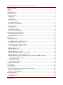
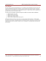
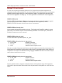
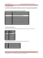
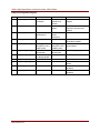
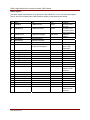
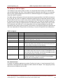
Vreelin Engineering Inc.
USB2.0 High-Speed Device Interface for
Altera SOPC Builder
User Manual
Core Facts
Provided with Core
Documentation
User Manual
Vreelin Eng. Inc.
Design File Formats
EDIF net list, Verilog Wrapper
747 Alice Ave.
Mountain View, CA
USA, 94041
Phone: (650) 386-5758
Fax: (650) 386-5758
E-mail:[email protected]
Website: www.vreelin.com
Extreme Performance
19 Megabytes/sec sustained
throughput over USB
(Cyclone II 100MHZ Avalon Bus)
Verification
only
Instantiation
Verilog
templates
Features
•
•
•
•
•
•
•
•
•
Test Bench with HDL Source license
Logo Certified by www.usb.org
Also supports Full Speed
12 pin ULPI I/F to external USB2 PHY
32 Bit Avalon Slave Interface
7 user endpoints plus control endpoint 0
Uses BRAM for endpoint FIFO’s
Complete Firmware
Windows XP Device Driver
Working End to End Example
Reference designs &
Reference Design on Cyclone 2C35
application notes
development board with SMSC 3300
USB2 PHY Daughter Card
Firmware
Complete Firmware stack provided
Host Software
Windows XP USB device driver and
supporting user mode libs
Core and Firmware is USB Logo Certified as a High-Speed
USB device by the USB Implementer’s Forum
Table 1: Example Implementation Statistics
Family
Example Device
Fmax
LE’s
BRAM
(MHz)
Design
Tools
Stratix 2™
EP2S60
150
1500
1+
Quartus 6
Stratix 1™
EP1S40
150
1500
1+
Quartus 6
Cyclone II™
EP2C35
150
1500
1+
Quartus 6
© 2007, Vreelin Engineering, Inc. All Rights Reserved. Vreelin and other designated brands included herein are trademarks of
Vreelin Engineering, Inc. * All other trademarks are the property of their respective owners.
NOTICE OF DISCLAIMER: Vreelin Engineering, Inc. is providing this design, code, or information "as is." By providing the design, code, or information as one possible
implementation of this feature, application, or standard, Vreelin makes no representation that this implementation is free from any claims of infringement. You are responsible
for obtaining any rights you may require for your implementation. Vreelin expressly disclaims any warranty whatsoever with respect to the adequacy of the implementation,
5.0
including but not limited to any warranties or representations that this implementation is free from claims of infringement and any implied warranties of merchantability or fitness
for a particular purpose.
USB2.0 High-Speed Device Interface for Altera* SOPC Builder
Table of Contents
Features .......................................................................................................................................................... 1
Applications.................................................................................................................................................... 4
General Description ......................................................................................................................................... 4
Functional Description ..................................................................................................................................... 6
USB 2.0 Protocol ......................................................................................................................................... 6
USB 2.0 PHY .............................................................................................................................................. 6
USB 2.0 SIE ................................................................................................................................................ 6
Dual Port RAM............................................................................................................................................ 7
Avalon Bus Interface.................................................................................................................................... 7
Control & Status Registers............................................................................................................................ 7
SOPC Builder Verilog Wrapper .................................................................................................................... 8
Firmware Overview ......................................................................................................................................... 9
Chapter 9 Support ........................................................................................................................................ 9
User Endpoint Firmware............................................................................................................................... 9
The Standard Configuration .......................................................................................................................... 9
USB Gross Condition Handling .................................................................................................................... 9
Non Standard Firmware Configurations........................................................................................................... 11
Modify the Standard Configuration ............................................................................................................. 11
Create Completely New Descriptors ............................................................................................................ 11
Write New Firmware.................................................................................................................................. 12
Host Software................................................................................................................................................ 13
Firmware High Level API .............................................................................................................................. 14
void USBInit(usb_dev* dev, int base, int irq) ............................................................................................... 14
int USBWrite(end_point, NoBlock, ptr, len)................................................................................................. 14
int USBRead(end_point, NoBlock, ptr, len) ................................................................................................. 14
int USBIoctl(end_point, int request, pvoid) .................................................................................................. 15
Requests applicable to endpoint 0 only:.................................................................................................... 16
Windows* XP user level API ......................................................................................................................... 18
DWORD USBInit(void) ............................................................................................................................. 18
DWORD USBOpen(int end_point) ............................................................................................................. 18
DWORD USBClose(int end_point) ............................................................................................................. 18
DWORD USBRead(int end_point, char *ptr, int len) .................................................................................... 18
DWORD USBWrite(int end_point, char *ptr, int len) ................................................................................... 18
DWORD USBIoctl(int end_point, DWORD request, void *inbuffer, DWORD inbuffersize, .......................... 19
void *outbuffer, DWORD outbuffersize) ..................................................................................................... 19
IOCTL_RESET_PIPE ............................................................................................................................ 19
IOCTL_GET_CONFIG .......................................................................................................................... 19
IOCTL_RESET_DEVICE ...................................................................................................................... 19
Usbhaldemo1.c and Usbapp.c ......................................................................................................................... 19
Core Modifications ........................................................................................................................................ 20
Core I/O Signals ............................................................................................................................................ 20
Avalon Memory Map..................................................................................................................................... 21
Microprocessor Bus Memory Map (Port B of Dual Port RAM)...................................................................... 21
Endpoint Configuration Space..................................................................................................................... 21
Endpoint Config Status Register.................................................................................................................. 22
Hard Coded Registers .................................................................................................................................... 23
USB Address Register ................................................................................................................................ 23
Control Register......................................................................................................................................... 23
www.vreelin.com
Vreelin Engineering, Inc.
USB2.0 High-Speed Device Interface for Altera*
Status Register ........................................................................................................................................... 24
USB Frame Number Register...................................................................................................................... 25
Interrupt Enable Register ............................................................................................................................ 26
Buffer Ready Register ................................................................................................................................ 27
Test Mode Register .................................................................................................................................... 27
Verification Methods ..................................................................................................................................... 28
The Hardware I/O Port Option........................................................................................................................ 29
HWIF Port Signals ..................................................................................................................................... 29
User Hardware Demo ................................................................................................................................. 29
Sequence to Sink Data from USB................................................................................................................ 30
Sequenece to Source Data to USB ............................................................................................................... 30
Use of HWIF_EP_Adrs .............................................................................................................................. 30
Use of HWIF_Stall and HWIF_Ready ......................................................................................................... 30
Clock Implications ..................................................................................................................................... 30
© 2007, Vreelin Engineering, Inc. All Rights Reserved. Vreelin and other designated brands included herein are trademarks of
Vreelin Engineering, Inc. * All other trademarks are the property of their respective owners.
3
USB2.0 High-Speed Device Interface for Altera* SOPC Builder
USB 2.0
USB 2 PHY
ULPI
USB SIE
32 bit
P
o
r Dual Port BRAM
t
A
P
o
r
t
B
32 bit
Avalon Bus
I/F
(SLAVE)
Avalon Bus
Control & Status Registers (32 bit wide)
Figure 1: USB 2.0 Core Block Diagram
Applications
The Vreelin Engineering USB2.0 High-Speed Device Interface for Altera SOPC Builder adds a HighSpeed USB 2.0 compliant device interface to the user’s SOPC Builder design. This interface is suitable
for USB centric, high performance, designs as well as for legacy port replacement applications.
General Description
The Vreelin USB 2 High Speed Device core and associated software implements a complete end to end
solution for connecting an Altera SOPC Builder design to a Windows XP host using high speed USB 2
transactions. Complete firmware for the Altera NIOS2 microprocessor is provided in standard C and a
stable, high performance Windows XP device driver is provided for the host PC. A demo application
running under Micro C/OS2 RTOS and an associated application running on Windows XP not only
demonstrate the operation of the core, device driver, and firmware, but also provide an excellent starting
point for a user’s design.
Overall performance of the USB 2 High Speed Device core is limited only by the speed of the Avalon bus
and Windows XP. The core will sustain maximum possible USB 2.0 High-Speed data rates. The core
provides ping-pong memories for each endpoint. No real-time movement of data by the NIOS processor
or user hardware is required to meet USB specifications. However, overall throughput of the system is
limited by the ability of the NIOS processor to move data in and out of the ping-pong memory. To achieve
maximum performance, the core needs ~15 million 32 bit transactions per second over Avalon. On a
Cyclone II (2C35) NIOS development board running Avalon and NIOS at 100MHZ, sustained USB
throughput of 19 megabytes/sec using 512 byte bulk transfers is achievable using the supplied Vreelin
software and firmware. This includes a complete Windows XP device driver, Windows XP support library,
Windows XP demo console application, NIOS HAL firmware layer, UCOS 2 RTOS, and demo firmware
application. Using the same software with the core configured with the optional hardware I/O port,
sustained USB throughput of 44 megabytes/sec is achievable with 512 byte bulk transfers – essentially
the maximum possible USB performance for bulk transfers.
The USB 2 High Speed Device core is implemented in approximately 1500 LE’s on most current Altera
devices including Cyclone II and requires a minimum of one block RAM (BRAM). Older devices require a
minimum of four block RAM’s. Adding more BRAM’s to the design provides more space for endpoint
FIFO’s. The BRAM’s are configured as a dual port RAM with asynchronous clocked ports. Verilog source
code is provided for the dual port RAM so that a designer can make appropriate design tradeoffs in the
dual port RAM’s implementation. As supplied, the dual port RAM is implemented as 2K by 32 bit using
four BRAM’s. A 32 bit, byte addressable slave interface is implemented over Avalon.
www.vreelin.com
Vreelin Engineering, Inc.
USB2.0 High-Speed Device Interface for Altera*
On the USB side, the core uses the latest ULPI USB 2 PHY interface which requires only 12 pins. The
core implements completely asynchronous dual clock domains. The USB SIE side of the core runs off the
ULPI PHY 60MHZ clock and the Avalon bus interface side runs off the Avalon clock.
Note that for an understanding of USB 2.0 and all of its ramifications there are several sources. The USB
2.0 specifications available at www.usb.org is the standard definition, Mindshare and others have various
books on the protocol, and Cypress Semiconductor has one of the best introductions in it’s “Easy USB FX
User Manual” which can be downloaded at www.cypress.com. Read Chapter 1. Please note that in this
document and others, I refer to Windows XP. Microsoft for good or bad, defines the host O/S operating
requirements that USB devices must meet. Linux and other O/S’s are compatible.
© 2007, Vreelin Engineering, Inc. All Rights Reserved. Vreelin and other designated brands included herein are trademarks of
Vreelin Engineering, Inc. * All other trademarks are the property of their respective owners.
5
USB2.0 High-Speed Device Interface for Altera* SOPC Builder
Functional Description
A functional description of the High-Speed USB 2.0 Device Core for Altera NIOS follows.
USB 2.0 Protocol
A detailed description of the USB 2.0 protocol is beyond the scope of this data sheet. For that kind of
description please refer to the USB 2.0 specification available from http://www.usb.org or to one of the
many books that are available.
For purposes of this data sheet, the USB 2.0 protocol multiplexes many devices over a single, half
duplex, bit serial bus. The bus is designed to be plug and play. The bus runs at 480 mega bits per
second. The PC always controls the bus and send tokens to each device specifying the required action.
Each device has an address on the USB 2.0 bus and has one or more endpoints that are sources or
sinks of data. All devices have endpoint 0, the system control endpoint. Unlike all other endpoints,
endpoint 0 is full duplex and single buffered. The Vreelin device core has seven additional endpoints for
the user’s application. When the PC wants to send data to a device’s endpoint, it sends an OUT token,
along with the address of the device and the endpoint number followed by the data. To receive data, the
PC sends an IN token with the device address and endpoint number and waits for data from the device.
To perform system level control functions, including plug and play, SETUP tokens are sent by the PC to
endpoint 0, along with setup information.
The USB 2.0 core consists of 6 major hardware components and 4 software components.
USB 2.0 PHY
The PHY is user supplied. It can be any of the ULPI complaint PHY’s on the market. The PHY’s primary
job is to handle the bit level serialization and de-serialization of USB 2.0 traffic. To do this it must also
detect and recover the USB bus clock. This clock runs at 480MHZ and is too fast for practical
implementation as programmable logic in the FPGA as well as in many ASIC’s. Since 480MHZ is also
high for a core clock, the PHY interfaces to the USB 2.0 core on a byte serial basis and generates a
60MHZ clock. This clock runs the SIE side of the USB 2.0 core. It can also be used to run the entire
FPGA if desired.
Vreelin has had great success as well as achieved USB Logo Certification using the SMSC USB3300
ULPI PHY.
USB 2.0 SIE
The USB 2.0 SIE (SIE) handles the serialization and de-serialization of USB traffic at the packet level
and the multiplexing and demultiplexing of USB data to and from the core’s endpoints. The SIE also
handles USB 2.0 state transitions such as suspend, resume, and USB reset. The SIE implements the
protocol specified in Chapter 8 of the USB 2.0 specification.
The SIE interfaces to the PHY using an industry standard set of handshaking lines called the ULPI
interface. ULPI requires only 12 pins and is ideal for FPGA designs. Data to the FPGA from the USB is
received from the PHY, error checked, and loaded into the appropriate area of the dual port RAM. Data
www.vreelin.com
Vreelin Engineering, Inc.
USB2.0 High-Speed Device Interface for Altera*
from the FPGA to be sent over the USB is loaded from the block RAM, protocol wrapped and presented
to the PHY a byte at a time when the protocol allows.
The status of current USB transactions are signaled by the SIE to the status register. Certain conditions
can be enabled through the interrupt enable register to generate an interrupt on the Avalon bus.
Dual Port RAM
The Dual Port RAM is the data storage area between the USB SIE and the Avalon bus interface. It is fully
dual port. Port A is used by the SIE, port B is used by the Avalon bus interface. For performance
reasons, both ports are 32 bits wide. Port A is clocked by the ULPI PHY clock at 60MHZ and port B is
clocked by the Avalon bus clock at any speed desired. There is no required phase relationship between
the clocks.
Data from USB is stored in the appropriate locations in Dual Port RAM by the SIE through port A. The
user’s firmware or hardware accesses this data through port B over the Avalon. Data to the USB is
loaded by the user through the Avalon Bus to port B into the appropriate locations in the Dual Port RAM.
When the PC requests data from the device, the SIE accesses this data from port A.
The Dual Port RAM is “seen” by the SIE as eight endpoint FIFO’s, plus a control register area that defines
how the memory is laid out. Each FIFO is implemented as ping pong buffers to help support the high
throughput possible with USB 2.0. One buffer can be used for a current USB transaction while the other
buffer is available to the user application for processing. The storage areas are treated as FIFO’s only
from the SIE’s point of view. The user’s firmware or hardware can access the storage as ordinary RAM
over Avalon. Dual Port RAM based registers are located in the lower 64 bytes of Dual Port RAM that
control the layout of each endpoint’s FIFO’s in Dual Port RAM, the communications direction (OUT or IN)
of the endpoint, the endpoint’s type (Bulk/Interrupt or ISO), and certain internal state information.
To provide flexibility to the designer and to minimize the resources used by the USB 2.0 Core, the Verilog
source code for the dual port RAM implementation is provided. The designer can then optimize for his
particular needs. As supplied, 4 2kx8 BRAM’s are used. More or less can be used as long as port A is 32
bit addressable and port B is 8, 16, and 32 bit addressable.
Avalon Bus Interface
The Avalon bus interface connects port B of the dual port RAM and the Control & Status Registers to the
Avalon bus. This is a slave interface that looks like RAM. Byte, half word and word transfers are
supported.
Control & Status Registers
The Control and Status Registers control operation of the USB 2.0 core, report the core’s status, sets the
USB function address, indicates buffer ready condition to the USB SIE, and enable interrupts. These
registers are implemented as registers in hardware, not block RAM. They are accessed over Avalon in
the upper 16K byte address space of the core. They are the address register, control register, status
register, current USB frame number register, interrupt enable register, buffer ready register and the mode
control register.
© 2007, Vreelin Engineering, Inc. All Rights Reserved. Vreelin and other designated brands included herein are trademarks of
Vreelin Engineering, Inc. * All other trademarks are the property of their respective owners.
7
USB2.0 High-Speed Device Interface for Altera* SOPC Builder
The address register contains the function address of the USB 2.0 core. It is written by firmware and must
be set in accordance to Chapter 9 commands from the host.
The control register currently only implements a master enable bit. Until this bit is set, the SIE is held in
reset and will not respond to USB traffic.
The status register reports on current USB conditions such as USB Reset, USB Suspend, USB Resume,
USB Disconnect, setup packet received, and buffer complete status for each endpoint and each buffer.
The frame number register reports the most current USB SOF packet received. Both major 1MS frames
and minor 128 microsecond frames are reported.
The interrupt enable register determines which status register events and which endpoints cause an
interrupt to the Avalon. Reading the status register clears any current interrupt.
The buffer ready register indicates the ready status of each endpoint’s two FIFO buffers to the SIE. Only
buffers that are indicated as ready will by loaded or unloaded by the SIE in response to USB transactions.
SOPC Builder Verilog Wrapper
The Verilog wrapper is used by SOPC Builder to set the address range for the USB 2.0 core in the
Avalon address map. The wrapper instantiates the core and does the master address decode for Avalon
bus transactions.
www.vreelin.com
Vreelin Engineering, Inc.
USB2.0 High-Speed Device Interface for Altera*
Firmware Overview
The firmware has 3 main areas of operation. First, the firmware implements all of the requirements of the
USB 2.0 specification chapter 9, otherwise known as the “chapter 9 firmware” that operates against
endpoint 0. Second, the firmware provides both low level primitives and high level abstraction interfaces
to the user endpoints (1 to 7). Unix style stream I/O interfaces such as USBRead, USBWrite, and
USBIoctl are provided for each of the user endpoints. Third, the firmware handles gross USB conditions
such as USB Reset, Suspend, Resume, and Disconnect.
Chapter 9 Support
Chapter 9 of the USB specification concerns itself with the enumeration process with the USB host the
device is plugged into. This process is complex and takes a newly plugged in USB 2.0 high speed device
to the configured or enumerated state. In this state, the USB Host knows what the device implements and
how to talk to it. During normal operation, there are other endpoint 0 communications that can take place
that the Chapter 9 firmware will handle. For the most part, this is transparent to the designer. All that is
required is for the microprocessor system to ether provide an interrupt handling routine that services the
device core’s status register interrupt and dispatches to the appropriate firmware or polls the status
register on a frequent enough interval and dispatches to the appropriate firmware.
User Endpoint Firmware
Endpoints 1 to 7 make up the user endpoints of the device core. Each endpoint may be programmed to
be ether an IN or OUT endpoint (IN to the USB Host, OUT from the USB Host); may have packet sizes of
from 2 to 512 bytes each for non-ISO endpoints and from 2 to 1024 bytes each for ISO endpoints. There
is no requirement to use all of the user endpoints.
The Standard Configuration
In it’s simplest use case, the firmware defaults to the standard configuration. The standard configuration
is designed to make it easier for a designer to add a USB interface to a design. Endpoints 1 to 3 are
setup “out of the box” as OUT endpoints (from the HOST) as non-ISO and 512 byte packet size.
Likewise, endpoints 4 to 6 are setup as IN (to the HOST) as non-ISO and 512 byte packet size. Endpoint
7 is setup as an INTERRUPT IN (to the host) endpoint with a packet size of 16 bytes and is intended to
be used for device status to the host. Using the USBRead, USBWrite, and USBIoctl function calls, Unix
like stream I/O is provided to the designer over the user endpoints back to the host.
In addition, the standard configuration includes a tested Windows XP device driver that supports the
above endpoint configuration and a user level support library and demo application. With the Host set of
software plus the provided firmware, the designer can add 6 high speed USB 2.0 endpoints to his design,
plus a status endpoint and access all of them from application space under Windows XP out of the box.
USB Gross Condition Handling
Since USB is “Plug and Play” code is provided to handle the Plug and Play aspects of USB. USB
Disconnect happens when the user unplugs the USB cable. The firmware will properly shut down I/O and
© 2007, Vreelin Engineering, Inc. All Rights Reserved. Vreelin and other designated brands included herein are trademarks of
Vreelin Engineering, Inc. * All other trademarks are the property of their respective owners.
9
USB2.0 High-Speed Device Interface for Altera* SOPC Builder
return the core to the USB unenumerated state waiting for a new plug in. USB Reset happens on host
command. Similar firmware comes into play as for USB Disconnect. USB Suspend / Resume handles the
go to sleep and wakeup aspects of USB and safely suspends and resume I/O operation.
In addition using the USBIoctl high level abstraction interface, user provided call backs can be installed
the will be “called out” on any of the above conditions to handle user specific situations. Please note that
all of these callbacks are called at interrupt service time (if interrupts are being used) and should be short
and to the point.
www.vreelin.com
Vreelin Engineering, Inc.
USB2.0 High-Speed Device Interface for Altera*
Non Standard Firmware Configurations
If the standard configuration will not provide the needed functionality for a designer, then the firmware
provides several options to produce non standard configurations.
Modify the Standard Configuration
This method will work best when the desired configuration is not too different from the standard
configuration. Perhaps the number or direction of endpoints are different or the packet sizes need to be
tweaked. This approach works as follows:
1. The designer must modify the descriptors provided for the standard configuration in usb.c using the
structure definitions in usb.h. These descriptors must match the desired USB configuration.
2. Call USBInit as usual. This loads the modified descriptors into the firmware.
3. Then appropriate calls must be made to USBIoctl to set each endpoint’s characteristics to match what
was set in the modified descriptors. These calls can include setting the base address in dual port RAM for
each endpoint’s buffers and the size of those buffers.
Warning:
The designer must be careful in the assignment of endpoint base addresses and sizes since there is no
contention checking between endpoints in the dual port RAM. The core will happily DMA anywhere into
dual port RAM it is told to for an endpoint including right over other endpoint’s buffer areas.
4. Use the other USBIoctl calls to set call backs for USB Reset, Suspend, and Disconnect.
5. Continue with normal startup and operation
The calls USBRead, USBWrite, and other USBIoctl calls are still available once the endpoints have been
customized as long as the right call is made to the right endpoint – I.E. – USBRead to an OUT endpoint,
USBWrite to an IN endpoint for example.
Create Completely New Descriptors
If the designer needs a USB configuration that is completely different from the standard configuration
supplied, then completely different USB descriptors will be needed. This approach will require a
considerably higher understanding of USB at several levels. However, using the files usb.c and usb.h it is
feasible to build something unique without writing firmware from scratch. Some things to consider:
Look at the layout of the descriptors at the top of usb.c and their corresponding structure definitions in
usb.h.
Look at the function USBInit in usb.c. Follow it’s logic flow and notice how the descriptors are copied into
data structures. These descriptors are presented to the USB host on demand through the chapter 9 code
in the firmware. The chapter 9 function, GetDescriptor parses chapter 9 requests and selects the
appropriate descriptor for transmission over USB. Both USBInit and GetDescriptor may have to be
modified.
© 2007, Vreelin Engineering, Inc. All Rights Reserved. Vreelin and other designated brands included herein are trademarks of
Vreelin Engineering, Inc. * All other trademarks are the property of their respective owners.
11
USB2.0 High-Speed Device Interface for Altera* SOPC Builder
The function Init_Usb_Interfaces will have to be modified to match the endpoint configurations in the new
descriptors.
The standard configuration API calls USBRead, USBWrite, and USBIoctl can still be used if desired.
Write New Firmware
The files usb.c and usb.h contain a great deal of code that can be reused, if new firmware is desired.
Most of the low level functions are quite useful in a customer firmware situation. Complete hardware
interface definitions are provided later in this document.
In any of the above cases, Vreelin Engineering is available on consulting basis to help with customization.
Any modifications on the device (core) side, must match with the device driver and INF file on the PC
side. Modifying the Windows XP device driver is a non-trivial exercise. Vreelin is available to help with
this on a consulting basis.
If even more customization is required, see the firmware source code. Lower level software primitives are
provided to manipulate all endpoints as well as move date in and out of the dual port RAM. Vreelin is
available on a consulting basis to customize any of this for special designer needs.
www.vreelin.com
Vreelin Engineering, Inc.
USB2.0 High-Speed Device Interface for Altera*
Host Software
The vast majority of hosts will be Windows PC’s. A completely functional Windows XP device driver that
supports the standard configuration is supplied in source and object form with this release. This device
driver brings all 7 user endpoints out to ring 3 application space. A support library and demo application is
provided to show how to use the device driver.
The device driver will handle the following changes in the USB core’s firmware without modification:
•
•
•
•
•
endpoint direction: IN or OUT
endpoint maximum packet size
endpoint type: Interrupt or BULK
number of active endpoints (up to the max of 7)
Note that the Windows XP device driver does not currently support ISO transactions. If ISO endpoint
transactions are required or if integration with other Windows XP system components are required, then a
custom device driver will be needed. Vreelin Eng. Inc. is available on a consulting basis to develop such
device drivers.
© 2007, Vreelin Engineering, Inc. All Rights Reserved. Vreelin and other designated brands included herein are trademarks of
Vreelin Engineering, Inc. * All other trademarks are the property of their respective owners.
13
USB2.0 High-Speed Device Interface for Altera* SOPC Builder
Firmware High Level API
All of the standard configuration firmware and it’s API calls are contain in usbdevice.c. All of the data
definitions and structures are contained in usbdevice.h. These files are located in the usbdevice\hal\src
and usbdevice\hal\inc directories. In addition, a simple demo firmware application, usbdemo1.c is also
located in usbdevice\drivers_and_examples directory.
void USBInit(usb_dev* dev, int base, int irq)
• usb_dev* dev
• int base
• int irq
pointer to USB dev structure (a global in user code)
base address of USB core’s on microprocessor bus
interrupt assigned to the core
USBInit will perform all one time core initialization including registering the core’s interrupt handler with
the supported RTOS or HAL. The usb_dev structure should be allocated in the user’s global area and
must be valid during interrupt processing time.
int USBWrite(end_point, NoBlock, ptr, len)
•
•
•
•
•
int end_point
int NoBlock
char * ptr
int len
returns
endpoint number 1 to 7
1 implies do not block on space available
pointer to the buffer to write from
maximum number of bytes to write
number of bytes written
This routine will write up to len bytes from the memory addressed by ptr and send it to the USB endpoint
buffer as space is available. If NoBlock = 0, then USBWrite will suspend the caller until all of the
requested data has been written. If NoBlock = 1, then only the available data will be written including 0
bytes if no buffer space is available. USBWrite will return the number of bytes written in all cases.
int USBRead(end_point, NoBlock, ptr, len)
•
•
•
•
•
int end_point
int NoBlock
char * ptr
int len
returns
endpoint number 1 to 7
1 implies do not block on data available
pointer to the buffer to read into
maximum number of bytes to read
number of bytes read
This routine will read up to len bytes from end_point. If NoBlock is set to 1, then only the number of bytes
available up to len will be read. Otherwise, USBRead will block (ether suspend the task or spin loop
depending on the environment) until the requested number of bytes in len are available. US
www.vreelin.com
Vreelin Engineering, Inc.
USB2.0 High-Speed Device Interface for Altera*
int USBIoctl(end_point, int request, pvoid)
• int end_point
• int request
• void *pvoid
endpoint number 0 to 7
IOCTL request number, defined in usb.h
generic pointer to specific parameters
Just as in most O/S’s, USBIoctl is the catch all call. The request determines the functionality of the call.
Request applicable to the user endpoints ( 1 to 7):
1. I_SET_OUT_IN
Pvoid points to an unsigned int that is 0 for OUT and 1 for IN. Note that and endpoint set to OUT receives
data from the HOST and one set to IN sends data to the host.
2. I_SET_VALID
Pvoid points to an unsigned int that is 1 for VALID and 0 for non VALID. And endpoint must be set to
VALID to operate. If set to non VALID, the endpoint will ignore all I/O from the host. VALID is a maser
enable bit for the endpoint.
3. I_SET_STALL
PVOID points to an unsigned int that is 1 for STALL and 0 for non STALL. If STALL is set, then all I/O
attempts from the host for this endpoint will received a STALL response. STALL is used in USB to
indicate a need for host interaction. It is not used often. For normal operation, set the endpoint to non
STALL.
4. I_SET_ISO
PVOID points to an unsigned int that is 1 for ISO and 0 for non ISO. Isochronous endpoints have special
characteristics. The endpoint may have a max packet size of up to 1024 as opposed to 512 for BULK.
Packets are not handshaked and are not retried.
5. I_SET_BASE
PVOID points to an unsigned int that contains the offset in 32 bit words from the beginning of dual port
RAM to the start of the first packet buffer of two for the endpoint. It is the designer’s responsibility to
layout the dual port RAM and to make I_SET_BASE and I_SET_SIZE calls that do not result in buffer
overlap or writing of packet data to undesired locations.
6. I_SET_SIZE
© 2007, Vreelin Engineering, Inc. All Rights Reserved. Vreelin and other designated brands included herein are trademarks of
Vreelin Engineering, Inc. * All other trademarks are the property of their respective owners.
15
USB2.0 High-Speed Device Interface for Altera* SOPC Builder
PVOID points to an unsigned int that contains the size of the endpoints packet buffers in bytes. Non ISO
user endpoints can be up to 512 bytes in size. ISO endpoints can be up to 1024 bytes in size. Two packet
buffers will be allocated in dual port RAM one after the other, so that if a designer uses this call with a
value of 512 for example, 1024 bytes will be reserved.
NOTE: Functions 1 to 6 require that an appropriate set of USB descriptors be supplied to the firmware
using USBIoctl calls to endpoint 0 as described in this document below.
Requests applicable to endpoint 0 only:
I_STARTUSB
This call starts the core. The core may be stopped and started at any time. However, stopping the core
during USB enumeration or other host driven event times will cause unpredictable results. This call is
primarily intended to allow the designer to setup the core characteristics with the core stopped and then
to release the core for operation.
I_STOPUSB
This call stops the core. Not intended for normal use.
I_SETUSBRESETCB
Sets a user callback to be called when a USB Reset happens. PVOID points to a structure defined in
usb.h that has a function pointer and a user data pointer that will be passed to the callback when called.
The call back provided will be called at interrupt time, so it should be short and to the point.
I_SETUSBDISCONCB
Sets a user callback to be called when the USB cable is unplugged. PVOID points to a structure defined
in usb.h that has a function pointer and a user data pointer that will be passed to the callback when
called. The call back provided will be called at interrupt time, so it should be short and to the point.
I_SETUSBSUSPENDCB
Sets a user callback to be called when the USB goes into suspend. PVOID points to a structure defined
in usb.h that has a function pointer and a user data pointer that will be passed to the callback when
called. The call back provided will be called at interrupt time, so it should be short and to the point.
I_SETUSBCONFIGCB
Sets a user callback to be called when the firmware has received and accepted a configuration request
from the host. PVOID points to a structure defined in usb.h that has a function pointer and a user data
pointer that will be passed to the callback when called. The current configuration number will be passed
as well. The call back provided will be called at interrupt time, so it should be short and to the point.
www.vreelin.com
Vreelin Engineering, Inc.
USB2.0 High-Speed Device Interface for Altera*
I_SETUSBSOFCB
Sets a user callback to be called when a USB Start of Frame token is received. Note this is the 1
millisecond master start of frame, not the 125 microsecond sub frame. PVOID points to a structure
defined in usb.h that has a function pointer and a user data pointer that will be passed to the callback
when called. The current frame number will be passed as well. The call back provided will be called at
interrupt time, so it should be short and to the point.
See usb.c and usb.h for the rest of the IOCTL calls.
© 2007, Vreelin Engineering, Inc. All Rights Reserved. Vreelin and other designated brands included herein are trademarks of
Vreelin Engineering, Inc. * All other trademarks are the property of their respective owners.
17
USB2.0 High-Speed Device Interface for Altera* SOPC Builder
Windows* XP user level API
All of the files composing the Windows XP device driver, support library and demo application are
contained in device_drivers\vreelindd. The device driver files are in the sub directory driver, and the demo
application files and support library are in the subdirectory usbapp. The support library is usb.cpp and
usb.h, the demo application is usbapp.cpp. The demo application is a Windows XP console application.
DWORD USBInit(void)
Finds the USB device in Windows XP device name space and performs magical incantations to get the
device ready for individual calls to USBOpen for the endpoints. If the magic works, returns
ERROR_SUCCESS, otherwise, the call returns the error encountered.
DWORD USBOpen(int end_point)
Open a handle to the specified endpoint, end_point. This function calls CreateFile, passing in a name
space path to the individual endpoint. Returns ERROR_SUCCESS on successful open, otherwise the
Windows XP system error code is returned.
DWORD USBClose(int end_point)
Close the handle to the specified endpoint, end_point.
DWORD USBRead(int end_point, char *ptr, int len)
• Int end_point
endpoint to read from
• Char *ptr
buffer pointer to read into
• Int len
maximum number of bytes to read
Will read the number of bytes requested from the specified endpoint into the buffer pointed to by ptr. The
default settings will suspend the calling thread until the number of requested bytes are read. Returns on
completion or error such as the USB device being unplugged. USBRead will return the number of bytes
read or the error code if an error occurs.
DWORD USBWrite(int end_point, char *ptr, int len)
• int end_point
endpoint to write to
• char *ptr
buffer to write from
• int len
maximum number of bytes to write
Write the specified number of bytes to the endpoint from the buffer pointed to by ptr. Will suspend the
caller until len bytes are written. Returns the number of bytes written or the system error code if an error
occurs.
www.vreelin.com
Vreelin Engineering, Inc.
USB2.0 High-Speed Device Interface for Altera*
DWORD USBIoctl(int end_point, DWORD request, void *inbuffer, DWORD inbuffersize,
void *outbuffer, DWORD outbuffersize)
• int end_point
endpoint to control
• DWORD request
DeviceIoControl code
• void *inbuffer
input buffer
• DWORD inbuffersize
input buffer size
• void *outbuffer
output buffer size
• DWORD outbuffersize
output buffer size
Passed request through to the specified endpoint using DeviceIoControl. See the documentation for
DeviceIoControl. Some requests are generic to all file I/O under Windows and would apply here. Others
are device driver specific. The Windows XP device driver supplied with the core supports the following
DeviceIoControl calls:
IOCTL_RESET_PIPE
This call will cause all I/O operations and the data toggle bit to be reset. Not normally needed
IOCTL_GET_CONFIG
Will return in the outbuffer the complete configuration descriptor unless the descriptor is larger than
outbuffersize, in which case it will return outbuffersize bytes of the descriptor.
IOCTL_RESET_DEVICE
Reset the entire device including all endpoints. Not normally used.
Usbhaldemo1.c and Usbapp.c
Usbhaldemo1.c implements a demo firmware application that uses the firmware high level API as
implemented in usb.c and usb.h. Usbapp.cpp similarly uses the ring 3 user API to talk to the Windows XP
device driver. The two programs “play” together and are meant as a starting point for a designer’s
application.
© 2007, Vreelin Engineering, Inc. All Rights Reserved. Vreelin and other designated brands included herein are trademarks of
Vreelin Engineering, Inc. * All other trademarks are the property of their respective owners.
19
USB2.0 High-Speed Device Interface for Altera* SOPC Builder
Core Modifications
The only modification that can be done with a net list license is the implementation of the dual port RAM.
The Verilog source code is provided in the file dual_port_ram.v.
Core I/O Signals
The USB 2.0 core is an Avalon slave complaint interface intended to be used with the Altera NIOS.
Table 1: Core I/O Signals
Signal
Signal
Description
Direction
ULPI Interface
clock
Input
60MHZ ULPI clock for SIE generated by USB PHY
ULPI_Dir
Input
When High, the PHY is outputting to ULPI_Data, the core see this on ULPI_Data_I
ULPI_Next
Input
Data in or out on ULPI_Data is required to be valid on the next rising edge of clock
ULPI_Stop
Output
When the core is transmitting on ULPI_Data, ULPI_Stop going high will signal the end
of transmission.
ULPI_Data[7:0]
Bi-Dir
ULPI bi-directional data bus – direction controlled by ULPI_Dir
ULPI_Reset
Output
When high causes the external ULPI PHY to reset. Used to recover from PHY error
conditions
AVALON Bus Interface
clk
Input
AVALON Bus clock
reset
Input
AVALON Bus Reset – resets entire core
address[31:0]
Input
AVALON Address bus bits 31 to 15 used for decode of core’s address space
byteenable[3:0]
Input
AVALON byte lane selects, each bit corresponds to one of the 4 byte lanes on the
AVALON data bus, supported by the core in the block RAM address space, not in the
hard register space
writedata[31:0]
Input
AVALON Data bus into the core
read
Input
R/W select line, 0 = write, 1 = read
Chipselect
Input
AVALON bus select line, 1 = valid cycle for this core, 0 = invalid
readdata[31:0]
Output
AVALON Data bus out of the core
Irq
Output
Interrupt line to the AVALON bus active high
www.vreelin.com
Vreelin Engineering, Inc.
USB2.0 High-Speed Device Interface for Altera*
Avalon Memory Map
The following is the memory layout of the USB 2.0 Core as seen from the Avalon bus. The base address
of the core is set by the NIOS2 utility SOPC Builder when the core is instantiated into the NIOS2 project
Microprocessor Bus Memory Map (Port B of Dual Port RAM)
Offset
Description
0 to 0x80
Endpoint configuration space
0x80 to 0x87
Setup packet storage location (8 bytes)
0x88 to 0x3fff
RAM for endpoint buffers Allocation is controlled by
settings in endpoint configuration space.
0x4000 to 0x7fff
Hard coded register space.
0x4000
USB Address
0x4004
Control
0x4008
Status
0x400C
Current USB frame number
0x4010
Interrupt Enable
0x4014
Buffer Ready
0x4018
Mode Control (for USB certification)
Note all offsets are byte offsets.
Endpoint Configuration Space
Each endpoint has 4 32 bit locations located sequentially and arranged by endpoint number. I.E.:
Offset
Description
0x00
Endpoint 0
0x10
Endpoint 1
0x20
Endpoint 2
0x30
Endpoint 3
0x40
Endpoint 4
0x50
Endpoint 5
0x60
Endpoint 6
0x70
Endpoint 7
For each endpoint there are four 32 bit words defining the endpoints behavior:
Offset
Description
0x00
Endpoint Config Status Register
0x04
Unused, but reserved
0x08
Buffer 0 count: 0 to 1024
0x0c
Buffer 1 count: 0 to 1024
© 2007, Vreelin Engineering, Inc. All Rights Reserved. Vreelin and other designated brands included herein are trademarks of
Vreelin Engineering, Inc. * All other trademarks are the property of their respective owners.
21
USB2.0 High-Speed Device Interface for Altera* SOPC Builder
Endpoint Config Status Register
BIT
Name
SET
CLEAR
Comments
31
EP_VALID_BIT
Endpoint operations
No endpoint
Master enable / disable bit for the
are allowed
operations are
endpoint
allowed
30
EP_STALL_BIT
Endpoint is stalled
Endpoint is not
When set, a STALL is the only
stalled
response to the host for this
endpoint
29
EP_OUT_IN_BIT
Endpoint responds to
Endpoint responds
IN transactions
to OUT
ISO endpoint
Non ISO endpoint
In/Out is with respect to the host.
transactions
28
EP_ISO_BIT
ISO endpoints do not send or
expect ACK's or NAK’s
27
26
EP_DATA_TOGGLE_BIT
EP_BUFFER_SELECT_BIT
Data toggle is 1 and
Data toggle is 0 and
Used as weak form of
will expect or send a
will expect or send
synchronization.
DATA 1 packet
a DATA 0 packet
Current buffer is the
Current buffer is
second buffer
the first buffer
This field allows up
Implements ping pong buffers
25
EP_PACKET_SIZE_MS
MSB of the packet size
15
EP_PACKET_SIZE_LS
LSB of the packet size
17
EP_PACKET_SIZE_QWA
Used to index RAM in 32 bit
12
EP_BASE_MS
MSB of the base offset in RAM of
to 1024 byte packets
chunks
the buffers
0
EP_BASE_LS
LSB of the base offset in RAM of
the buffers
www.vreelin.com
Vreelin Engineering, Inc.
USB2.0 High-Speed Device Interface for Altera*
Hard Coded Registers
USB Address Register
Contains the Host assigned USB address of the device. Takes on values from 0 to 127. An address of 0
implies that the device is unenumerated and is the default address of all USB devices at plug in time.
Reset by hardware to 0. Program by the microprocessor under supplied Chapter 9 firmware control.
Control Register
Only one bit, bit 31. When clear, the USB SIE is paused and will not respond to any USB activity. When
set, the SIE operates normally.
© 2007, Vreelin Engineering, Inc. All Rights Reserved. Vreelin and other designated brands included herein are trademarks of
Vreelin Engineering, Inc. * All other trademarks are the property of their respective owners.
23
USB2.0 High-Speed Device Interface for Altera* SOPC Builder
Status Register
The status register reports status on the operation of the USB device core. It is an auto clear register.
That is, when the microprocessor reads the status register, all bits reported are cleared.
Bit
Name
Set
Clear
23
USB Reset
USB Reset active
Normal
comments
Will remain set for
up to 3 ms
22
USB Suspend
USB Suspend active
Normal
Will remain set for
as long as suspend
which can be hours
21
USB Disconnect
USB Cable unplugged
USB Connect
USB detach
detection
20
FIFO Buf Rdy
EP 0 Pkt Received
19
FIFO Buf Free
EP 0 Pkt Transmitted
18
Setup Packet
EP 0 Setup Pkt Rcv’ed
17
SOF Packet
Start of Frame Rcv’ed Value
SOF’s happen every
in Start of Frame Register
125 us in high
speed mode!
16
High Speed
USB in high speed
USB in full speed
15
EP 7 2
nd
14
EP 6 2
nd
Buf Comp
Buffer Complete
Not processed
Buf Comp
Buffer Complete
13
EP 5 2
Not processed
nd
Buf Comp
Buffer Complete
Not processed
EP 4 2
nd
12
11
Buf Comp
Buffer Complete
Not processed
EP 3 2
nd
Buf Comp
Buffer Complete
10
Not processed
EP 2 2
nd
Buf Comp
Buffer Complete
Not processed
9
EP 1 2
nd
Buf Comp
Buffer Complete
Not processed
8
Not Used
EP 0 has only 1
buffer and it is bir
directional
st
Buffer Complete
Not processed
st
Buffer Complete
Not processed
st
Buffer Complete
Not processed
st
Buffer Complete
Not processed
st
Buffer Complete
Not processed
st
Buffer Complete
Not processed
st
7
EP 7 1 Buf Comp
6
EP 6 1 Buf Comp
5
EP 5 1 Buf Comp
4
EP 4 1 Buf Comp
3
EP 3 1 Buf Comp
2
EP 2 1 Buf Comp
1
EP 1 1 Buf Comp
Buffer Complete
Not processed
0
EP 0 Buf Comp
Buffer Complete
Not processed
EP 0 has only 1
buffer and it is bidirectional
www.vreelin.com
Vreelin Engineering, Inc.
USB2.0 High-Speed Device Interface for Altera*
USB Frame Number Register
The frame number register is composed of 2 fields, frame and microframe. Frames are sent once every
one millisecond and denote the beginning of a USB frame. All host scheduling starts at start of frame
time. The microframe field is the result of additional start of frame tokens sent once every 125
microseconds. Because of the potentially high rate interrupts this can generate when the USB is in high
speed mode, interrupt enable of start of frame should be used with caution. Frame count values are 11
bits and microframes are 3 bits.
Bit
Name
Comments
13
Frame MSB
0 to 2047
3
Frame LSB
2
Micro Frame MSB
0
Micro Frame LSB
0 to 7
© 2007, Vreelin Engineering, Inc. All Rights Reserved. Vreelin and other designated brands included herein are trademarks of
Vreelin Engineering, Inc. * All other trademarks are the property of their respective owners.
25
USB2.0 High-Speed Device Interface for Altera* SOPC Builder
Interrupt Enable Register
The interrupt enable register allows specific bits in the status register to generate an interrupt. There is
also a master enable bit so that all interrupts can be disable at once. When the status register is read,
and there is no further driver for the status bits causing the interrupt, the interrupt condition is cleared.
Alternatively, the interrupt enable bit can be cleared to prevent a long duration condition such as USB
Reset from continuously generating an interrupt.
Bit
Name
Comments
31
Master enable
Enables setting of all other enables
23
USB Reset IE
Enables USB Resets to generate an IRQ
22
USB Suspend IE
Enables USB Suspends to generate an IRQ
21
USB Disconnect IE
Enables USB disconnects to generate an IRQ
20
FIFO Buf Rdy IE
A received Data Packet on EP 0 will generate an IRQ
19
FIFO Buf Free IE
A successfully transmitted data packet on EP 0 will generate an
18
SETUP Pkt IE
A received setup packet will generate an IRQ
17
SOF Pkt IE
Start of Frame will generate an IRQ
16
High Speed IE
When the bus is in High Speed an Irq is generated
15
EP 7 2
nd
Buf Complete IE
IRQ on Buffer operation successful
14
EP 6 2
nd
Buf Complete IE
IRQ on Buffer operation successful
13
EP 5 2
nd
Buf Complete IE
IRQ on Buffer operation successful
12
EP 4 2
nd
Buf Complete IE
IRQ on Buffer operation successful
11
EP 3 2
nd
Buf Complete IE
IRQ on Buffer operation successful
10
EP 2 2
nd
Buf Complete IE
IRQ on Buffer operation successful
9
EP 1 2
nd
Buf Complete IE
IRQ on Buffer operation successful
8
Not used
7
EP7 1 Buf Complete IRQ
IRQ
st
IRQ on Buffer operation successful
st
IRQ on Buffer operation successful
st
IRQ on Buffer operation successful
st
IRQ on Buffer operation successful
st
IRQ on Buffer operation successful
st
IRQ on Buffer operation successful
st
IRQ on Buffer operation successful
st
IRQ on Buffer operation successful
6
EP6 1 Buf Complete IRQ
5
EP5 1 Buf Complete IRQ
4
EP4 1 Buf Complete IRQ
3
EP3 1 Buf Complete IRQ
2
EP2 1 Buf Complete IRQ
1
EP1 1 Buf Complete IRQ
0
EP0 1 Buf Complete IRQ
www.vreelin.com
Vreelin Engineering, Inc.
USB2.0 High-Speed Device Interface for Altera*
Buffer Ready Register
Each buffer for each endpoint has a corresponding buffer ready bit in this register. The firmware sets
each bit when that buffer is ready for ether USB IN or USB OUT traffic. Until that bit is set, an attempted
IN or OUT to the buffer will result in a NAK back to the host. Note that the ability of a buffer to handle an
IN or OUT is determined by the EP_OUT_IN_BIT in the corresponding endpoint’s ep_config_status word
in low memory. Also note that endpoint 0 has only one buffer and that it handles IN’s or OUT’s. This is
per the USB specification.
Bit
Name
Comment
15
EP 7 2
nd
Buffer Ready
Set when available for IN or OUT
14
EP 6 2
nd
Buffer Ready
Set when available for IN or OUT
13
EP 5 2
nd
Buffer Ready
Set when available for IN or OUT
12
EP 4 2
nd
Buffer Ready
Set when available for IN or OUT
11
EP 3 2
nd
Buffer Ready
Set when available for IN or OUT
10
EP 2 2
nd
Buffer Ready
Set when available for IN or OUT
9
EP 1 2
nd
Buffer Ready
8
N/A
7
EP 7 1 Buffer Ready
6
EP 6 1 Buffer Ready
Set when available for IN or OUT
End point 0 has only one buffer
St
Set when available for IN or OUT
St
Set when available for IN or OUT
St
Set when available for IN or OUT
St
Set when available for IN or OUT
St
Set when available for IN or OUT
St
Set when available for IN or OUT
5
EP 5 1 Buffer Ready
4
EP 4 1 Buffer Ready
3
EP 3 1 Buffer Ready
2
EP 2 1 Buffer Ready
1
EP 1 1 Buffer Ready
Set when available for IN or OUT
0
EP 0 Buffer Ready
Set when available for IN or OUT
St
Test Mode Register
The USB Implementer’s Forum, the organization that controls USB logo certification, requires all USB 2.0
device that operate at high speed to support the following test modes:
•
•
•
•
Test Mode J:
Sends a continuous Chirp J.
Test Mode K:
Sends a continuous Chirp K.
Test Mode NAK: Send a NAK in response to any valid packet. Ignore invalid packets.
Test Mode Packet:
Sends the “Luerker” packet over and over forever.
Each of these test modes are started by Chapter 9 commands via the firmware. Once received the test
mode register is set to the desired test mode. To exit the test mode requires a hardware reset. Test mode
0 is normal operation.
© 2007, Vreelin Engineering, Inc. All Rights Reserved. Vreelin and other designated brands included herein are trademarks of
Vreelin Engineering, Inc. * All other trademarks are the property of their respective owners.
27
USB2.0 High-Speed Device Interface for Altera* SOPC Builder
Verification Methods
The USB 2.0 core can be verified against any standard PC running Windows 2000 or XP using one of the
supplied reference designs and the Altera NIOS2 development boards and the SMSC USB3300 PHY
daughter card.
A complete USB 2.0 test bench environment for simulation is available from Vreelin Eng. Inc. when the
HDL source license is purchased.
www.vreelin.com
Vreelin Engineering, Inc.
USB2.0 High-Speed Device Interface for Altera*
The Hardware I/O Port Option
The Hardware I/O port option (HWIF) provides a very high speed direct interface to the USB SIE from
user provided hardware. Any of the 7 user endpoints may be redirected to the HWIF port. In conjunction
with the Vreelin supplied Windows XP device driver, sustained throughput of 44 megabytes a second
using bulk transfers is possible.
The HWIF redirects USB packet I/O from the internal core ping-pong buffers to the HWIF port whenever
bit 14 (EP_HW_IO) is set in an endpoint's configuration register by the microprocessor firmware. Packet
data from the PC (OUT's) or to the PC (IN's) can be redirected. Redirection can be changed on the fly by
the firmware. More than one endpoint can be redirected at a time. The HWIF port interface includes the
endpoint number so that use supplied hardware can differentiate between endpoint traffic. When packet
I/O is redirected to the HWIF port, it is the responsibility of the user supplied hardware to buffer data
appropriately and to keep up with the interface. Note however, that only packet payload is redirected, the
user is not responsible for CRC generation and checking or any other components of the USB protocol.
HWIF Port Signals
Signal
Direction
Description
clock
Input
60MHZ USB PHY clock – all signals active on rising edge
reset
Input
Master reset
HWIF_Active
Input
High when packet traffic to HWIF is active
HWIF_EP_Adrs[2:0]
Input
The endpoint number of the current packet. Can be used by user hardware to
HWIF_Next
Input
High when next byte in or out is valid on the data bus
HWIF_Error
Input
High when an transmission or reception error has occurred. This indicates the
decode when data source or sink to use.
current receive packet must be discarded or the current transmit packet must
be resent. Used by user hardware to control buffering.
HWIF_Data_Out [7:0]
Input
8 bit data in. Valid when HWIF_Next is high, one byte per clock
HWIF_Data_In [7:0]
Output
8 bit data out. Next byte must be valid on next clock when HWIF_Next is high
HWIF_Ready
Output
Asserted by user hardware within 3 clocks after HWIF_Active is high to signal
user hardware ready for data. If this does not happen, the USB SIE will send a
NAK in response to the current packet. Can be used with the HWIF_EP_Adrs to
selectively indicate ready or not ready for an end point.
HWIF_Stall
Output
Asserted by user hardware when a STALL condition is present. Will cause the
USB SIE to send a STALL in response to any packet. Can be used with the
HWIF_EP_Adrs to selectively STALL an end point.
User Hardware Demo
A example user hardware application is provided. The file is hwif_wrap.v. It is well commented. This file
implements a wrap application where data from USB is sinked over endpoint 1 into a ping-pong memory
and sourced over endpoint 4 back to USB.
© 2007, Vreelin Engineering, Inc. All Rights Reserved. Vreelin and other designated brands included herein are trademarks of
Vreelin Engineering, Inc. * All other trademarks are the property of their respective owners.
29
USB2.0 High-Speed Device Interface for Altera* SOPC Builder
Sequence to Sink Data from USB
• Wait for HWIF_Active to go high
• If ready to receive data, assert HWIF_Ready within 3 clocks
• Sink one byte of data from HWIF_Data_Out on each clock that HWIF_Next is high
• When HWIF_Active goes low, the transfer is complete. If HWIF_Error is high, then the transfer’s
CRC16 failed and the packet should be discarded. If HWIF_Error is high it will drop on the next
clock.
• If HWIF_Error was low indicating that the packet was received successfully, the last two bytes
presented on HWIF_Data_Out were the packet CRC16 value and should be discarded.
Sequenece to Source Data to USB
• Wait for HWIF_Active to go high
• If ready to transmit data, assert HWIF_Ready within 3 clocks
• Source one byte of data to HWIF_Data_In on each clock that HWIF_Next is high
• When data from the current packet is finished, drop HWIF_Ready on the clock following the last
byte of transfer. Note that zero length packets are legal as are short length packets. The maximum
length packet that may be transferred will depend on the setup of the endpoint’s descriptor by the
firmware. Maximum for Bulk is 512 bytes.
• Wait for HWIF_Active to go low. This may take several microseconds as the USB SIE is waiting for
the host to ACK, NAK, or timeout. If the host received the packet correctly, I.E., it ACK’ed the
transfer, then when HWIF_Active goes low, HWIF_Error will also be low. If an error occurs,
HWIF_Error will be high and the packet will need to be re-transmitted on the next packet
transaction against this endpoint. If HWIF_Error was high, it will go low on the next clock.
Use of HWIF_EP_Adrs
HWIF_EP_Adrs identifies the endpoint number of the current HWIF transaction. It is valid while
HWIF_Active is high. HWIF_EP_Adrs would allow user supplied hardware to support more than one
endpoint.
Use of HWIF_Stall and HWIF_Ready
HWIF_Ready normally indicates dynamic status of the user’s hardware to sink or source data. However
HWIF_Ready and HWIF_Stall can be used to indicate static not ready or Stall conditions. As long as
HWIF_Ready is low, any packet activity against the HWIF port will be NAK’ed. As long as HWIF_Stall is
high, any packet activity against the HWIF port will be STALL’ed.
Clock Implications
The HWIF port clock runs at 60MHZ and is derived from the USB PHY. It also runs the USB SIE. All
transactions and all signals of the HWIF port are synchronous to clock.
www.vreelin.com