1
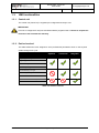
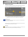
Smart Sight User Guide Document Asyril_AVIEW-XXX-XX_User_Guide_E Version v2.1 Articles AVIEW-XXX-XX--XX-XX-XX-XX Date 22.06.2015 Smart Sight - Asyril SA User Guide Introduction v2.1 © Copyright Asyril S.A. FO 32.03.118 Contents 1. INTRODUCTION ............................................................................................................................... 5 1.1. GENERAL INFORMATION ........................................................................................................... 5 1.2. OTHER MANUALS ...................................................................................................................... 6 1.3. HMI FUNCTIONALITIES.............................................................................................................. 7 1.3.1. Control unit ............................................................................................................................ 7 1.3.2. Parties involved..................................................................................................................... 7 2. SETTING UP THE SYSTEM ........................................................................................................... 8 3. CREATING AND CONFIGURING A RECIPE............................................................................ 10 4. CONFIGURING THE ASYCUBE ................................................................................................. 11 5. 6. 4.1. VIBRATIONS OF THE ASYCUBE PLATFORM AND RESERVOIR .................................................. 11 4.2. CONFIGURING THE VIBRATION PROCESS ............................................................................... 12 CONFIGURING THE VISION ....................................................................................................... 14 5.1. SELECTING THE VISION PROCESS TYPE ................................................................................. 15 5.2. CONFIGURING THE ILLUMINATION PARAMETERS .................................................................... 16 5.3. PROGRAMMING THE VISION MODEL ....................................................................................... 18 PROGRAMMING THE VISION MODEL ..................................................................................... 19 6.1. OVERVIEW .............................................................................................................................. 19 6.1.1. Tricks and shortcuts ........................................................................................................... 20 6.2. PRELOCALIZATION .................................................................................................................. 21 6.2.1. Overview .............................................................................................................................. 21 6.2.2. Configuring the tool: "MODEL" tab .................................................................................. 21 6.2.3. Configuring the tool: "BOUNDING BOX" tab .................................................................. 26 6.3. MODEL FINDER ....................................................................................................................... 27 6.3.1. Overview .............................................................................................................................. 27 6.3.2. « Settings » tab ................................................................................................................... 27 6.3.3. Configuring the tool: "Detection" tab ................................................................................ 28 6.3.4. Configuring the tool: “Detection (Advanced)” tab........................................................... 31 6.3.5. Configuring the tool: « ControlSettings » tab.................................................................. 32 6.3.6. Configuring the tool: « Control (Model) » tab ................................................................. 33 6.3.7. Configuring the tool: « Control (Advanced) » tab........................................................... 34 6.3.8. Configuring the tool: "RESULTS" tab .............................................................................. 35 6.4. EXCLUSION ZONE DEFINITION ................................................................................................ 37 6.4.1. Empty Picking Zone Growing (EPZG) ............................................................................. 38 6.4.2. Empty Picking Zone Region (EPZR) ............................................................................... 40 6.5. LOCALIZATION RESULTS ........................................................................................................ 45 6.6. FEEDING INFORMATION .......................................................................................................... 46 User Guide Smart Sight – Asyril SA 3/52 Smart Sight - Asyril SA User Guide Introduction 7. 8. v2.1 © Copyright Asyril S.A. FO 32.03.118 END OF PROGRAMMING ............................................................................................................ 47 7.1. CLOSING THE ASYVIEW TEACHING WINDOW .......................................................................... 47 7.2. TESTING THE VISION MODEL................................................................................................... 48 7.3. PERMANENTLY SAVING THE VISION MODEL ........................................................................... 49 TECHNICAL SUPPORT ................................................................................................................ 50 8.1. FOR A BETTER SERVICE …..................................................................................................... 50 8.2. CONTACT ................................................................................................................................ 50 REVISION TABLE ..................................................................................................................................... 51 User Guide Smart Sight – Asyril SA 4/52 Smart Sight - Asyril SA User Guide Introduction v2.1 1. Introduction 1.1. General information © Copyright Asyril S.A. FO 32.03.118 This document is the property of Asyril SA; it may not be reproduced, modified or communicated, in whole or in part, without our prior written authorisation. Asyril SA reserves the right to modify any information contained in this document for reasons related to product improvements without prior notice. Before using the product, please read this entire document in order to ensure that the product is used correctly. However, if you encounter difficulties when using the product, do not hesitate to contact our customer service department. In this manual, the safety information that must be respected is split into three types: "Danger", "Important" and "Note". These messages are identified as follows: DANGER! Failure to respect this instruction may result in serious physical injury. DANGER! This instruction identifies an electrical hazard. Failure to respect this instruction may result in electrocution or serious physical injury due to an electric shock. IMPORTANT! Failure to respect this instruction may result in serious damage to equipment. NOTE: The reader's attention is drawn to this point in order to ensure that the product is used correctly. However, failure to respect this instruction does not pose a danger. Reference … For more information on a specific topic, the reader is invited to refer to another manual or another page of the current manual. IMPORTANT! Asyril cannot be held responsible for damage to property or persons caused by failure to respect the instructions specified in the "Safety instructions" paragraph. It is the customer's responsibility to inform the personnel concerned. NOTE: All dimensions and values in this manual are expressed in millimetres (mm) User Guide Smart Sight – Asyril SA 5/52 Smart Sight - Asyril SA User Guide Introduction 1.2. v2.1 © Copyright Asyril S.A. FO 32.03.118 Other manuals The table below provides a list of documents supplied with the product. Each of these manuals forms an integral part of the set of documentation associated with the product. This manual contains all the information for the users on how to use and configure a new recipe (feeding and vision recognition). Manual title Reference Description of the content Contains a technical description of the Smart Sight Operating Manual SIGHT-XXX- product, its functionalities and 02_Operating_Manual provides maintenance and transport information concerning the product Contains a description of the product's Smart Sight Programming manual SIGHT-XXX- operation and the information relating 02_Programming_Guide to communication and to using the product in terms of programming Smart Sight User Guide SIGHT-XXX-02_User_Guide THIS MANUAL Table 1-1: Other manuals User Guide Smart Sight – Asyril SA 6/52 Smart Sight - Asyril SA User Guide Introduction 1.3. © Copyright Asyril S.A. v2.1 FO 32.03.118 HMI functionalities 1.3.1. Control unit The control unit (Vision PC) is supplied pre-configured and ready to use. IMPORTANT! This unit is configured for Asyview and HMI software programs ONLY! Failure to respect this instruction will invalidate the warranty. 1.3.2. Parties involved This table defines the roles assigned to each professional permitted to work on the Asyview system during its life cycle. Operator Technician Integrator Acquiring an image Login/Logout Select a recipe Start/Stop the system Create/Modify a recipe Add/Modify an operator Calibrate Advanced access to Asyview Advanced access to the HMI Table 1-2: Parties involved User Guide Smart Sight – Asyril SA 7/52 Smart Sight - Asyril SA User Guide Setting up the system 2. v2.1 © Copyright Asyril S.A. FO 32.03.118 Setting up the system The system is pre-configured by Asyril with the ordered components and corresponding architecture. By defaut we will describe the simple case “1 Asycube + 1 camera”. Figure 2-1: Home page of the HMI: (1) show the architecture of the connected and preconfigured devices; (2) access to the configuration steps and monitoring. IMPORTANT NOTE If you have several cameras (Asycube camera, control camera, etc.), the "asyview" screen will be duplicated for each camera. Here below (Figure 2-2) is a simple description of what to settle and the main procedure after placing the Asycube and vision devices on the machine. IMPORTANT! Those parameters have to be set in the begginining of the setting up of the machine. Every modification of these parameters will break the calibrations and the recipes. User Guide Smart Sight – Asyril SA 8/52 Smart Sight - Asyril SA User Guide Creating and configuring a recipe v2.1 © Copyright Asyril S.A. FO 32.03.118 Figure 2-2: quick description of the different tasks to operate when settling a new Smart Sight configuration See the HMI User Manual within the interface for detailed information about these functionnalies: Live, Image configuration, Calibration. User Guide Smart Sight – Asyril SA 9/52 Smart Sight - Asyril SA User Guide Creating and configuring a recipe 3. v2.1 © Copyright Asyril S.A. FO 32.03.118 Creating and configuring a recipe Different level of recipe exist and allow easy access, loading and saving of the different level of the machine as well as mixing configuration depending on the application. A Vision recipe has a *.vrec extension and contains all of the data necessary to configure the complete vision and feeding system. The next chapters provide a tutorial describing how to configure a new recipe. However, the information contained in this chapter also applies to modifying an existing recipe. The different steps described in this chapter are resumed in Figure 3-1. Figure 3-1: main scenario to configure or modify a vision and feeding recipe User Guide Smart Sight – Asyril SA 10/52 Smart Sight - Asyril SA User Guide Configuring the Asycube v2.1 © Copyright Asyril S.A. FO 32.03.118 4. Configuring the Asycube 4.1. Vibrations of the Asycube platform and reservoir Step 1 Click on the «asycube» button Step 2 Click on the "Platform" / “Reservoir” tab Modify and test (a) the vibration parameters of the standard movements to adapt them to Step 3 Step 4 your components: - Vibrations of the Asycube platform and reservoir (b) - Pay particular attention to configure also the vibration time (batch) (c) Check that the parts vibrate uniformly in the right directions, without coming out of the platform using buttons in the home tab or in the shortcut. Figure 4-1: Adjusting the parts feeding parameters Figure 4-2: Test of the part displacements on the shortcuts button IMPORTANT NOTE The vibration time must always be configured as the time required to the parts to cross the platform in the corresponding direction. User Guide Smart Sight – Asyril SA 11/52 Smart Sight - Asyril SA User Guide Configuring the Asycube v2.1 © Copyright Asyril S.A. FO 32.03.118 NOTE 2 The vibration buttons (D) are only made available outside production. The Asyview must be in "configuration" mode in order for the buttons to appear. If this is not the case, click on the "stop" button under the Asyview shortcuts tab. 4.2. Configuring the vibration process Step 1 Click on the «asycube» button Step 2 Click on the "Process" tab Step 3 Step 4 Click on the "Planar plate" or "Structured plate" button to load the default parameters associated with your platform or load an existing configuration. If necessary, modify the paremeters of the process sequences NOTE: You can freely modify these parameters (duration, sequence, order of vibrations) and work also in advanced mode if necessary in order to configure the sequences specific to the feeding and recirculation phases. In all cases, remember to finish with a stabilisation time to prevent the parts from moving when a photo is being taken. Step 5 Use the simulator to control the behaviour of the process Figure 4-3: Defining the vibration sequences User Guide Smart Sight – Asyril SA 12/52 Smart Sight - Asyril SA User Guide Configuring the Asycube v2.1 © Copyright Asyril S.A. FO 32.03.118 Depending on the number of parts detected on the Asycube platform, it is possible to configure a specific vibration sequence. Between each configured sequence, the vibration time will be interpolated linearly. All the configured batches can be used in the sequence. To distribute the parts uniformly on the platform and take into account the position of the parts on the platform, the “calculated” option is included in the sequence. In this case, the algorithm will automatically define the vibration time and the optimal batch to apply. A typical sequence may be: Calculated Flip Stabilization In order to reduce the component stabilisation time, the Asycube platform may be machined (grooves, holes, etc.). In this case, the vibration sequence must be adapted to the type of platform (so that the parts are directly positioned in the grooves or holes for example). In the case of a grooved platform, a typical vibration sequence may be: Flip Forward Backward Figure 4-4: Example of a grooved platform In "advanced" mode, it is possible to differentiate the desired vibration sequence for a feeding and recirculation phase as: Feeding: o this sequence is normally used at the initial step or at the end of a production when none or not a lot of parts are in the field of view. Its goal is to transport the parts from bulk to the field of view Recirculation: o this sequence should prevent an overflow of parts in the field of view by preventing any part to come in the field of view Working: o it corresponds to the optimal state where the aim is to compensate the taken parts and to distribute the parts on the platform. The feeder should work most of the time with this manner. If not, the different thresholds and sequences should be modified. The cycle time is also directly related to this configuration. In the “normal” mode, only the Working sequences are configurable. The Feeding and Recirculation ones are automatically set up. User Guide Smart Sight – Asyril SA 13/52 Smart Sight - Asyril SA User Guide Configuring the vision 5. v2.1 Click on the «vision» button Step 2 Click on the “teaching" tab Step 3b FO 32.03.118 Configuring the vision Step 1 Step 3a © Copyright Asyril S.A. For a new configuration: choose the type of process to be used for this recipe: control or localisation (see § 5.1) and click on the “add” button. This will open the teaching window. To modify the configuration, click on the “modify” button. This will open the teaching window. NOTE The Asyview state will change to "teaching" in the header screen. Wait until the state has changed to "teaching" before moving on to the next step. The teaching window will be opened at that time. Figure 5-1: Starting the configuring of the vision model Figure 5-2: opening of the teaching window User Guide Smart Sight – Asyril SA 14/52 Smart Sight - Asyril SA User Guide Configuring the vision 5.1. © Copyright Asyril S.A. v2.1 FO 32.03.118 Selecting the vision process type Vision tools are preconfigured to allow easier, faster and reliable teaching and working processes. These tools are grouped in two main functionalities: “Control” and “Localisation”. Table 5-1 describes their use and content. Included vision process Feeder Info Description Exclusion zone Prelocalisation vision Pitch & Toss and position functionality Type of Number of acquired images CONTROL Detection of one specific feature on the image, mainly used for purpose of x presence checking, orientation or (x) 1 LOCALISATION position alignment error. Optimized detection of several/all parts in the field of view for purpose of localization, orientation, pitch & toss 1 - 15 x sorting and feeder management. x x x (different lighting conditions and intensity) Table 5-1: Description of the vision processes and their functionalities NOTE The feeding information is automatically available if the camera is linked to an Asycube. For a control camera, this feature is not used. User Guide Smart Sight – Asyril SA 15/52 Smart Sight - Asyril SA User Guide Configuring the vision 5.2. © Copyright Asyril S.A. v2.1 FO 32.03.118 Configuring the illumination parameters Adjust the illumination type and exposure time as well as the number of images (see Step 4 section 5.2). You can test the acquired image(s) on this tab. Figure 5-3: illumination parameters on the HMI The parameters available on the timesets are used to configure the image acquisition process: - exposure time [ms] : real acquisition time of the camera to take the picture - illumination time [ms] : time in which the light is on - illumination offset [ms] : time with the light on before to take the picture - time out [ms] : minimum time between two acquisitions - backlight intensity [from 0 to 100 %] - frontlight intensity [from 0 to 100 %] Illumination time Illumination offset Exposure time 0 10 20 30 40 50 60 70 Time [ms] Figure 5-4: Defining exposure time and illumination time User Guide Smart Sight – Asyril SA 16/52 Smart Sight - Asyril SA User Guide Configuring the vision v2.1 © Copyright Asyril S.A. FO 32.03.118 The illumination time must be longer than the exposure time. In order to ensure that the lighting (DOAL or backlight) is at full power when the photo is taken, it is necessary to delay the image acquisition by using the illumination offset and to switch off the lighting one to two milliseconds after the image acquisition is completed. Figure 5-4 illustrates this phenomenon. NOTE In general, only modify the Exposure time and Backlight / Frontlight intensities. The other parameters will then automatically adjust to optimize the sequence. For more advanced configuration it is still possible to set manually all parameters. On the HMI you can add or remove a timeset and test the whole sequence of acquisition/illumination. The displayed image can be selected by clicking on the corresponding timeset or with the arrows and selector in the images received area. IMPORTANT NOTE 1: With the localization process: The timeset 1 will always be used for the prelocalization operation. For this reason, it must correspond to the backlight illumination. The timeset 2 can correspond to DOAL or backlight illumination IMPORTANT NOTE 2: Visually check that the image displayed on the screen is correct, as the entire Vision model will be based on this photo! User Guide Smart Sight – Asyril SA 17/52 Smart Sight - Asyril SA User Guide Configuring the vision 5.3. Step 5 v2.1 © Copyright Asyril S.A. FO 32.03.118 Programming the Vision model Proceed to the vision model programmation on the teaching window (the button “↔” on the HMI allows to easily switch from the HMI window to the Vision teaching window) For information about the different parameters and available option in the teaching window, refer to chapter 6 “Programming the Vision model”. IMPORTANT NOTE: To take in consideration the adjustment of the timeset, click on the “Run” button. This action must be done at least one time when programming a new recipe to allow the correct allocation of the pictures. Figure 5-5: Vision teaching window User Guide Smart Sight – Asyril SA 18/52 Smart Sight - Asyril SA User Guide Programming the Vision model v2.1 6. Programming the Vision model 6.1. Overview © Copyright Asyril S.A. FO 32.03.118 By clicking on add or modify on the HMI teaching tab, the following window will then appear: Figure 6-1: General overview of the Asyview Teaching window Ref. Designation st (A) 1 level of tabs (B) 2 (C) 3 (D) Buttons associated with rd the 3 level of tabs. Description Each tab corresponds to a specific tool: - Prelocalization - Model Finder - Empty Picking Zone Growing (EPZG) - Empty Picking Zone Region (EPZR) - Localization Results - Feeding information nd level of tabs This set of tabs notably contains the "+" tab which enables to activate one model and also to apply several models to detect the good parts (for example when different parts have to be detected as the good ones). In this case, the system will add the results of each detection and ensure to not detect twice the same position. rd level of tabs The content of these tabs will be described in the following sections th The main buttons used include: - "Run" button "Run continuously" button (E) 4 level of tabs Clicking on the tabs will display the specific content in zone (F). (F) Zone specific to each tab The content of this zone will be described in detail in the following sections (G) Image selector Select the image you want to display in this selector (original image, train impage, with markers of the results, etc.) (H) Image This screen displays the image chosen in the selector (G) User Guide Smart Sight – Asyril SA 19/52 Smart Sight - Asyril SA User Guide Programming the Vision model v2.1 © Copyright Asyril S.A. FO 32.03.118 6.1.1. Tricks and shortcuts By right clicking on the 2 - nd tabs level (B) it is possible to access to functionnalities as: Activation & de-activation of a model: o This last one is kept in memory but can be de-activated for test purpose for instance o Note that it must have at least 1 active prelocalization model, 1 model finder and 1 feeding information model to allow a correct behavior of the system. - Removing a model: o This is definitive, no way to reload it (only if you had previously saved a recipe by reloading it) o Note that it must have at least 1 active prelocalisation model, 1 model finder and 1 feeding information model to allow a correct behavior of the system. - Copy From/To: o Allow to import the model parameters from a previously configured one or to export them to a specified target o - Note that this function is available only inside the current recipe. Image selection o Allow to define which image has to be used at each step of the vision process o Note that the prelocalisation is applied always on the first picture, usually with backlight illumination The Run button on top left allows running all analysis in the right order to reactualize the results if the acquisition timesets or a previous model have changed or to take new pictures. NOTE: The button “Run” has to be run at least one time when modifiying or creating a vision recipe to load the timeset configuration. nd Figure 6-2: Run Once button; right click on 2 tabs level to select image and copy/paste features User Guide Smart Sight – Asyril SA 20/52 Smart Sight - Asyril SA User Guide Programming the Vision model 6.2. v2.1 © Copyright Asyril S.A. FO 32.03.118 Prelocalization 6.2.1. Overview The prelocalization tool thresholds the picture and then inspects it for discrete blobs of connected pixels. Results may be filtered depending on their geometrical characteristics but mainly on their area. This first step allows locating fastly all candidates of good parts to be picked on the surface of the Asycube. To configure this tool, you must select the surface of your parts (in pixels or in mm depending on the calibration used) as well as a threshold value (greyscale value) used to transform each portion of the image into black & white. 6.2.2. Configuring the tool: "MODEL" tab Step 0 Click on the "Prelocalization" tab then on "Model" and finally on the "Settings" tab 3 -a 0 4 1 2 3 -b Figure 6-3: "Prelocalization" tool, 01\Model\Settings Step 1 Choose a "Hard Threshold (fixed)" type threshold Step 2 Choose the polarity of your parts (black on white background or vice versa) a- In the image selector, choose Current.Histogram b- Depending on the histogram, change the threshold value of the number of pixels Step 3 according to the level of grey as shown in the Figure 6-3. Click on the Step 4 button to run the tool and observe the resulting detected area by selecting "LastRun.InputImage" from the image selector. Modify the threshold value if necessary and run again if necessary. User Guide Smart Sight – Asyril SA 21/52 Smart Sight - Asyril SA User Guide Programming the Vision model © Copyright Asyril S.A. v2.1 FO 32.03.118 IMPORTANT NOTE The threshold represents the limit between a part and the background in the greyscale st range (1 to 255). Depending on the chosen illumination for the 1 image, the polarity might be inverted if the parts are light on a dark background. 6.2.2.1. Picking area Optionnaly it is possible to reduce the zone in which you want to find components. Step 5 Step 6 Click on the Region tab to display the screen below: You can draw a rectangle by choosing "cog rectangle", otherwise search the entire image by selecting < None – Use Entire Image > 5 6 Figure 6-4: "Prelocalization" tool, 01\Model\Region User Guide Smart Sight – Asyril SA 22/52 Smart Sight - Asyril SA User Guide Programming the Vision model v2.1 © Copyright Asyril S.A. FO 32.03.118 6.2.2.2. Filtering the results Step 7 Click on the Measurements tab to display the screen below: 10 7 9 8-a 8-b Figure 6-5: "Prelocalization" tool, 01\Model\Measurements Configure the "Area" property: a- Choose a type of "filter" measurement and an "include" value range Step 8 b- At this stage of the configuration process, we do not know the pixel surface of the parts, therefore choose quite a wide variation range (for example from 10 to 10,000). We will narrow this variation range later. Configure the "Connectivity" property: Step 9 Choose a type of "filter" measurement and an "exclude" value range IMPORTANT NOTE: The value range must be set to "include 0-0" if you want to detect the hole in a part The value range must be set to "include 1-1" if you want to detect the external outline of a part Step 10 If necessary, add a new property by clicking on the "Add new" button and configure it as well. Step 11 Click on the User Guide button to run the tool Smart Sight – Asyril SA 23/52 Smart Sight - Asyril SA User Guide Programming the Vision model v2.1 © Copyright Asyril S.A. FO 32.03.118 6.2.2.3. Analysing the results Step 12 Click on the Results tab to display the screen below: 13 12 Blob too small 14 Blob too big Figure 6-6: "Prelocalization" tool, 01\Model\Results Step 13 Select "LastRun.InputImage" from the image selector The table displayed on this tab lists the parts found, the associated area and the connectivity. Step 14 Examine the area of each component found and determine the smallest and the largest area for which a single component is found, as illustrated in the figure below: NOTE: When you select a line in the table, the corresponding blob is displayed in blue in the LastRun image and vice versa. Blob surface Blob surface area too large area too small Blob size correct Figure 6-7: Defining the area acceptance range User Guide Smart Sight – Asyril SA 24/52 Smart Sight - Asyril SA User Guide Programming the Vision model Step 15 v2.1 © Copyright Asyril S.A. FO 32.03.118 Return to the Measurement tab Modify the area range accepted as a result of the observations made in step 14, then run Step 16 the tool again. Check that all blobs surround just one part only. Otherwise, adjust the area again. 15 16 Blob not detected:OK Figure 6-8: "Prelocalization" tool, 01\Model\Measurements NOTE: The threshold value may also need to be adjusted; to do this, vary the value chosen in step 3. User Guide Smart Sight – Asyril SA 25/52 Smart Sight - Asyril SA User Guide Programming the Vision model v2.1 © Copyright Asyril S.A. FO 32.03.118 6.2.3. Configuring the tool: "BOUNDING BOX" tab Step 17 Click on the Bounding Box tab to display the screen below: NOTE Pay particular attention to the configuration of this tab if you have chosen to detect a hole in a part. In fact, the surrounding rectangle (subsequently called the "bounding box") must contain the ENTIRE part! Figure 6-9: "Prelocalization" tool, 01\Bounding Box\Settings In the "scale factor" input field, choose a multiplication factor that makes it possible to Step 18 extend the initial bounding box. For non symmetrical part it is possible to unlock the fields and choose different value for each direction. NOTE The initial bounding box is defined as the smallest rectangle able to contain the entire blob: Blob Bounding box Enlarged bounding box Figure 6-10: Defining the "Blob" and "Bounding Box" Step 19 Check that your "extended bounding box" contains the entire surface area of the part: In the “Mode”, “Oriented” means that the bounding box will be oriented along the main Step 20 inertial axis of the part. For complex geometry it might be better to not orient this bounding box. The main effect occurs when computing the Empty Picking Zone Region (see §6.4.2) for which it is optimal when contour and box are the closest possible. User Guide Smart Sight – Asyril SA 26/52 Smart Sight - Asyril SA User Guide Programming the Vision model 6.3. v2.1 © Copyright Asyril S.A. FO 32.03.118 Model finder 6.3.1. Overview The "Model Finder" tool enables to train the model of a correct part (pattern) with which the application will be able to differentiate correct parts from incorrect parts (notably for the detection of pitch and toss). The search is applied on all candidates located with the prelocalizsation tool. It is able to match rotated and varying in size objects. 6.3.2. « Settings » tab Figure 6-11: “Model Finder” tool - settings The Model Finder tool is composed by a Geometrical Feature Detection that can optionnaly be followed by a second control. This last one can be again based on a geometrical model or on the characteristic of the surface. Table 6-1 describes their uses. Type Use case Geometrical Feature Standard case : pitch & toss differentiation & precise localization on the 1 Detection (default) or a 2 Geometrical Feature Two geometrical successive searches, possibly on different images: one Detection & Control for localization purpose, the other for pitch & toss differentiation. - nd st image Parts where the pitch & toss detail is not compatible with precise localization purpose - Parts where the pitch & toss detail has not the same position on all parts Geometrical Feature Geometrical detection followed by a control of the surface characteristics, Detection & Surface possibly on different images. Control - Contour detection for localization - Different surface characteristics between pitch & toss Note that the surfaces to detect must be repeatable also considering their imperfections. Table 6-1: Model Finder tool type User Guide Smart Sight – Asyril SA 27/52 Smart Sight - Asyril SA User Guide Programming the Vision model v2.1 © Copyright Asyril S.A. FO 32.03.118 The position of pick will be defined within this tool. By default it corresponds to the detection result and it is specified directly in the geometrical model. But precise localization and differentiation of the pitch & toss of parts can be done on different images. Therefore the output position result (pick position) can also be defined according to the specific need as explained in Table 6-2. Pick position output Output Remark Detection Pick position = Result of the By default geometrical detection Control Pick position = Result of the Not available with « Geometrical geometrical or surface control Feature Detection» Table 6-2: output position result configuration 6.3.3. Configuring the tool: "Detection" tab Step 0 Click on the Model Finder tab then on the Model tab and finally on the Train parameters tab to display the screen below: Figure 6-12: "Model Finder" tool, 01\Detection (Model) \Train Params Step 1 Choose the "patMax & PatQuick" algorithm Step 2 Click on the "Grab Train Image" button Step 3 Choose "Current.TrainImage" from the image selector User Guide Smart Sight – Asyril SA 28/52 Smart Sight - Asyril SA User Guide Programming the Vision model Step 4 v2.1 © Copyright Asyril S.A. FO 32.03.118 Click on the Train Region and Origins tab to display the screen below: Figure 6-13: "Model Finder" tool, 01\Detection (Model) \Train Region & Origins Step 5 Choose the shape most appropriate to your part (circle, rectangle, ellipse, etc.) Step 6 Adjust the shape to a typical part that you want to recognise as a correct part. Define the centre and orientation of the part Step 7 Tip: you can move the system of coordinates manually, but it is more accurate to use the "center origin" button NOTE: Pay particular attention to defining the centre of the reference as it is the coordinates of this point that will be sent to the robot as the "PickPosition" When the pattern has been programmed, click on the "Train" button in the "Train Params" Step 8 tab. The image of the model programmed is displayed in the window that was initially blue Figure 6-14: Trained geometrical feature User Guide Smart Sight – Asyril SA 29/52 Smart Sight - Asyril SA User Guide Programming the Vision model Step 9 v2.1 © Copyright Asyril S.A. FO 32.03.118 Click on the Run Params tab to display the screen below: Modify the parameters as follows: a- Algorithm: Best trained b- Mode: Search image c- Approx number to find: depends on the number of components to test on this Step 10 picture d- Accept threshold: relatively high (between 0.7 and 0.9) e- If necessary, modify the rotation angle value accepted for the components (in relation to the model programmed) and the scale if your correct parts are not all exactly the same size. Figure 6-15: "Model Finder" tool, 01\Detection (Model) \Run Params Step 11 Click on the button to run the tool Select "LastRun.OutputImage" from the image selector And check that the parts that you Step 12 have defined as "correct" are accepted and that the others are rejected. Otherwise, modify the threshold value according to the score of incorrect parts (displayed in the results table) User Guide Smart Sight – Asyril SA 30/52 Smart Sight - Asyril SA User Guide Programming the Vision model v2.1 © Copyright Asyril S.A. FO 32.03.118 6.3.4. Configuring the tool: “Detection (Advanced)” tab Figure 6-16 : "Model Finder" tool, 01\Detection (Advanced) Step 13 Click on the Detection (Advanced) tab to display the screen below: Rotation: allows adjusting the rotation angle given in the result (pick position/orientation) - Enabled: the orientation will follow the detected part (only available if the search angle is not fixed to 0 in the Run parameters of the model). An optional offset can be added. Step 14 Disabled: constant orientation, eventually with adding an offset value Score: - Enabled: filter the results to to this score (only if this value is bigger than the accept threshold defined in the “Detection (Model)/Run Params” parameters) - Disabled: sort the result with the accept threshold defined in the “Detection (Model)/Run Params” parameters (step 10). Step 15 Click on the button to run the tool NOTE : The use of the score may be helpful to work with a not too high acceptance threshold in the Model Finder but to sort then only the best results. NOTE : Going on the picture gives the information about the ID of the corresponding part in the result informations. User Guide Smart Sight – Asyril SA 31/52 Smart Sight - Asyril SA User Guide Programming the Vision model v2.1 © Copyright Asyril S.A. FO 32.03.118 6.3.5. Configuring the tool: « ControlSettings » tab NOTE This tab is not available when chosing the option “Geometrical Feature Detection” Figure 6-17 : "Model Finder" tool, 01\ControlSettings Step 16 Click on the ControlSettings tab to display the screen below: Select the detection result you want to define as the reference : Step 17 - Choose the part you want as model (ID) - Click on SET => the system will load the train image, copy the corresponding region, and center in the model so you then only need to press the Train button. NOTE With the option « Geometrical Feature Detection & Surface Control », it is obligatory to choose the component to be used as a reference before going to the next step. User Guide Smart Sight – Asyril SA 32/52 Smart Sight - Asyril SA User Guide Programming the Vision model v2.1 © Copyright Asyril S.A. FO 32.03.118 6.3.6. Configuring the tool: « Control (Model) » tab NOTE This tab is not available when chosing the option “Geometrical Feature Detection” 6.3.6.1. “Geometrical Feature Detection & Control” The method is similiar to the Detection Model (§ 6.3.3). The goal is to detect the detail that distinguishes a good from a bad part (for pitch & toss for example) and not the entire part. The “train region” should so be adapted to the detail to detect. 6.3.6.2. “Geometrical Feature Detection & Surface Control” Figure 6-18 : "Model Finder" tool, 01\Control (Model) in the case of a “Surface Control” IMPORTANTE NOTE It is essential to have first selected the reference part and activated the « SET » button in the Control Settings before adjusting this model. User Guide Smart Sight – Asyril SA 33/52 Smart Sight - Asyril SA User Guide Programming the Vision model v2.1 Step 18 Click on the Control (Model) tab to display the screen below: Step 19 On the Train Params tab, click on Train to teach the model © Copyright Asyril S.A. FO 32.03.118 On the Run Params tab, adjust the parameters: Step 20 Step 21 The acceptance threshold might be quite high here because tiny differences between the parts should be usually detected - Eventually the angle and scale - Eventually the type of algorithme Click on the button to run the tool 6.3.7. Configuring the tool: « Control (Advanced) » tab NOTE: This tab is not available when chosing the option “Geometrical Feature Detection” This step is similar to the « Detection (Advanced) » tab (cf § 6.3.4) with the only remark that Step 22 the option Rotation is only available if the pick position is the Control result and not the Detection result (cf § 6.3.2). User Guide Smart Sight – Asyril SA 34/52 Smart Sight - Asyril SA User Guide Programming the Vision model v2.1 © Copyright Asyril S.A. FO 32.03.118 6.3.8. Configuring the tool: "RESULTS" tab In the previous tab, we configured the model to enable the tool to distinguish a correct part from an incorrect part. In this tab, we are going to test this model on each of the candidates selected by the prelocalization tool. Input image Prelocalization Blob + Bounding box Extended Bounding box Model Finder Pattern matching Accepted parts Refused parts Figure 6-19 "Model Finder" tool, Schematic algorithm The candidates found by the prelocalization tool are displayed in the "Inputs" tab of the tool in which we are currently working: "model finder". These inputs can also be consulted visually by selecting "CurrentInput.Image" from the image selector. User Guide Smart Sight – Asyril SA 35/52 Smart Sight - Asyril SA User Guide Programming the Vision model Step 23 v2.1 © Copyright Asyril S.A. FO 32.03.118 Click on the Results tab to display the screen below: Figure 6-20: "Model Finder" tool, 01\Results\Results Step 24 Click on the button to run the tool and obtain the results (this operation may take some time). Then click on the Output tab to get the list of the result. Select the image of interest from the image selector and check that the parts that you have defined as "correct" are accepted and that the others are rejected. Otherwise, Step 25 modify the values in the different models. The color codes on the bottom of the window indicate the number of parts having successfully passed the different steps. User Guide Smart Sight – Asyril SA 36/52 Smart Sight - Asyril SA User Guide Programming the Vision model 6.4. v2.1 © Copyright Asyril S.A. FO 32.03.118 Exclusion zone definition Name Method Define a zone of a certain thickness all around the part EPZG Empty Picking Zone Growing Define a geometric zone centred on the part picking point EPZR Empty Picking Zone Region Characteristics - Well adapted for parts with complex geometrical shape but when just a thin border is sufficient as exclusion zone - Very interesting in case of a small gripper tip and comparatively a large part: to be sure the parts are not touching each other - Very fast for a delimitation of only a few pixels, but time consuming for larger border - Can be combined with the EPZR - - - The outer shape of the excusion zone can be defined depending for example the geometry of the gripper tip. Different option to fit optimally the excusion zone with the part geometry and variance. Can be combined with the EPZG Table 6-3: EPZG and EPZR general description The Empty Picking Zone tools are used only on parts previously accepted by the model finder as explained below: Model Finder Pattern matching Accepted parts Refused parts Empty Picking Zone Region EPZR Accepted parts Refused parts Figure 6-21: "Empty Picking Zone" tools, Schematic algorithm User Guide Smart Sight – Asyril SA 37/52 Smart Sight - Asyril SA User Guide Programming the Vision model v2.1 © Copyright Asyril S.A. FO 32.03.118 6.4.1. Empty Picking Zone Growing (EPZG) The EPZG tool enables to define a zone all around the part in which no other part must be found. The goal is to prevent two parts being picked at the same time. The exclusion zone corresponds then to the growing of the contour of the part and has the effect of adding a border all around the part. Accepted Refused EPZG Kernel Size Figure 6-22: Empty Picking Zone Growing (EPZG) NOTE : This type of exculsion zone calculation is very time consuming. It is very well adapted to parts with a complex geometrical shape but for which only a thin border is sufficient. Step 0 Click on the "Empty Picking Zone Growing" The EPZG tool is configured in a very similar way to the Prelocalization tool. Therefore, in st order not to reproduce the same step twice, the 1 step consist of simply copy 1 to 1 the Step 1 prelocalization tool by right clicking on the “01” tab (see Figure 6-24). Click on the button to run the tool Define the value of the exculsion zone (Kernel size) (always an odd value and the maximal value is 49 pixels). Step 2 The Kernel size value must be selected in accordance with the size of the nozzle of your robot gripping device, in order not to take two parts at once during suction for example. EPZG Kernel Size Figure 6-23: Defining the "Kernel size" parameter User Guide Smart Sight – Asyril SA 38/52 Smart Sight - Asyril SA User Guide Programming the Vision model v2.1 © Copyright Asyril S.A. FO 32.03.118 Figure 6-24 : « Empty Picking Zone Growing » tab User Guide Smart Sight – Asyril SA 39/52 Smart Sight - Asyril SA User Guide Programming the Vision model v2.1 © Copyright Asyril S.A. FO 32.03.118 6.4.2. Empty Picking Zone Region (EPZR) 6.4.2.1. Overview The Empty Picking Zone Region (EPZR) tool is used to define a geometrical zone centred on the part picking point in which no other part must be found. The goal is to avoid two parts being picked at the same time. Refused Accepted Accepted Refused EPZR - Rectangle EPZR - circle Figure 6-25: Empty Picking Zone Region (EPZR) There are three types of EPZR optimized along the part shape as presented in Table 6-4. TYPE Method Characteristics Search between 2 defined shape (inner and outer) Very fast Only available for circular or Annulus area elliptical annulus Search inside the zone between the region of the Model Detection and a For simple geometries defined outer shape. For parts with variable size Detected region to Note: the Detection Region must boundary (default) be set as close as possible to the part contour. Search inside the zone between the contour of the part and a defined outer shape Part contour to For complex part shape boundary The slowest method Table 6-4: EPZR Types description User Guide Smart Sight – Asyril SA 40/52 Smart Sight - Asyril SA User Guide Programming the Vision model v2.1 © Copyright Asyril S.A. FO 32.03.118 6.4.2.2. Tool configuration The configuration is very similar for all the three types of EPZR: 1. Select the type, 2. Define the outer boundary of the exclusion zone 3. Parameterize the exclusion model in order to detect any element that could be present in the exclusion zone. 4. The last tab consists of the results list of all candidates that passed the previous model detection. All these steps are described here below. Figure 6-26: Empty Picking Zone Region tool, 01\Type Step 0 Click on the "Empty Picking Zone Region" Add a model by clicking on the “+”. The Exclusion Model tool is configured in a very similar way to the Prelocalization tool. Therefore, in order not to reproduce the same st Step 1 step twice, the 1 step consist of simply copy 1 to 1 the prelocalization tool by right clicking on the “01” tab. Click on the Step 2 button to run the tool Select the Type of EPZR to use (see Table 6-4 for the description of the types) If “Part Contour to Boundary” was selected, copy the Prelocalization parameters into the Step 2B “Contour” model by right clicking on the “01” tab. The same set of parameters can usually be used. Then click on the User Guide button to run the tool. Smart Sight – Asyril SA 41/52 Smart Sight - Asyril SA User Guide Programming the Vision model v2.1 © Copyright Asyril S.A. FO 32.03.118 Figure 6-27: Empty Picking Zone Region tool, 01\Boundary Figure 6-28: Empty Picking Zone Region tool, 01\Boundary with the Annular Area type Step 3 Select the Boundary tab to define the shape, size and offset for the outer shape. Step 4 Select the part ID that can be used as the reference to define the boundary. Step 5 Select the geometry of the boundary as well as its size and offset. The shape is draw around the selected part on the picture. NOTE: If the type Annular Area is selected, both the inner and the outer shape are defined here (Figure 6-28). User Guide Smart Sight – Asyril SA 42/52 Smart Sight - Asyril SA User Guide Programming the Vision model v2.1 © Copyright Asyril S.A. FO 32.03.118 Figure 6-29: Empty Picking Zone Region tool, 01\Exclusion Model Select the “Exlusion Model” tab: the detection inside the exclusion zone is always based Step 6 on the same tool than the Prelocalization. Simply adjust the minmal size of the element to detect and their threshold (exclusion criteria). Step 7 Select the “Settings” tab. Select the threshold or copy the Prelocalization tool into the Exclusion Model by right Step 8 clicking on the “01” tab. Step 9 The Min. Area value specifies the minimal size of any detected feature to be detected. Normally it can be let at the default value (10) but can be adjusted in case for example of a non uniform background. Step 10 Select the “Measurements” tab Step 11 Delete all the Properties or set all Filter to “Runtime” (could be present when copying the exclusion model from the prelocalization) User Guide Smart Sight – Asyril SA 43/52 Smart Sight - Asyril SA User Guide Programming the Vision model v2.1 © Copyright Asyril S.A. FO 32.03.118 Figure 6-30: Empty Picking Zone Region tool, 01\Results Step 12 Select the “Results” tab. Click on to execute the tool and get the results (this operation can take some time) Choose LastRun.OutputImage from the image selector. Verify that the accepted parts are: Step 13 - In the right direction (accepted byModel Finder) - Sufficiently far from any other parts (because accepted by the EPZR) If not, modify the values in the previous steps. User Guide Smart Sight – Asyril SA 44/52 Smart Sight - Asyril SA User Guide Programming the Vision model 6.5. v2.1 © Copyright Asyril S.A. FO 32.03.118 Localization Results Figure 6-31: Localization Results tool Step 1 Click on « Localization Results » to show the window as below : Step 2 Click on the button « Run ». It is possible to select the image to check. Verify the results : Step 3 User Guide - GREEN : accepted parts - ORANGE mark : EPZG rejected parts - VIOLET mark : EPZR rejected parts - RED mark : Detection Model rejected parts Smart Sight – Asyril SA 45/52 Smart Sight - Asyril SA User Guide Programming the Vision model 6.6. v2.1 © Copyright Asyril S.A. FO 32.03.118 Feeding information The "Feeding Information" tool enables the exact number of parts on the surface of the Asycube to be obtained as well as their position, regardless of their pitch and toss orientation. This information is then used to calculate the suitable vibration sequence (re-feed components, "flip" to better dispatch the components, etc.). The configuration is identical to that of the "Model Finder" but is only performed on the image with backlighting. Step 1 Step 2 Click on the Feeder information tab Refer to section 6.3.3 “Configuring the tool: "Detection" tab”” on page 28 and follow steps 1 to 8 NOTES The goal is to estimate the number of all parts that are on the plateform regardless their pitch & toss orientation. For this purpose, the backlight-illuminated image should be used to make the detection. It is also possible to apply several models to have a better estimation of the number of part if necessary, for example, when the geometry of parts is very different depending their orientation. Figure 6-32: "Feeding Information" tool, 01\Train Params Step 3 Step 4 Click on the button to run the tool and obtain the results Select "LastRun.OutputImage" from the image selector And check that ALL of the parts are detected. User Guide Smart Sight – Asyril SA 46/52 Smart Sight - Asyril SA User Guide End of programming v2.1 7. End of programming 7.1. Closing the Asyview teaching window Step 6 © Copyright Asyril S.A. FO 32.03.118 Click on the «apply» or «abort» button Figure 7-1: finalization of the vision model configuration IMPORTANT NOTE: The Asyview state will change to "Configuration - Idle" in the header screen (the LED is then yellow). Wait until the change is effective (LED to green again) before moving onto the next step. IMPORTANT! Your Vision model is NOT saved when you click on the «apply» button; you can test the modifications, but if the software is switched off, all modifications will be lost. For more information about permanently saving a recipe, refer to section 7.3. User Guide Smart Sight – Asyril SA 47/52 Smart Sight - Asyril SA User Guide End of programming 7.2. v2.1 © Copyright Asyril S.A. FO 32.03.118 Testing the vision model Step 1 Click on the «vision» button Step 2 Click on the «home» tab Step 3 Check the dispay results box Step 4 Choose the results to display Step 5 Click on the “Acquire” button to start the image analysis process Step 6 Check that the parts in the right direction are accepted and that the others are rejected. Figure 7-2: Vision-Home: Testing the Vision model Vibrate the Asycube using the shortcut area on the top of the HMI and repeat the steps 5 and 6. Step 7 If you are satisfied with the obtained results, you can save your recipe by referring to section 7.3. Otherwise, modify your recipe by returning on the teaching tab. User Guide Smart Sight – Asyril SA 48/52 Smart Sight - Asyril SA User Guide v2.1 7.3. © Copyright Asyril S.A. FO 32.03.118 Permanently saving the Vision model Figure 7-3: Permanently saving a recipe Step 1 Click on the «recipes» button Step 2 Click on the «asyview» tab It is possible to select the type of recipe to save. For example: only the feeder (Step 3) parameters or the whole recipe including all the cameras and feeders depending the configuration. (Step 4a) Step 4 If the descriptor of your recipe is no longer displayed, click on the "select" button and choose your recipe, then click on "open" Click on the "save" button to save on the selected recipe or the “save as” button for a new recipe. IMPORTANT NOTE: The Asyview and HMI state will change to "loading" in the header screen (the LED becomes yellow). Wait until the state has changed to "Configuration – Idle" (green LED) before moving on to the next step (this operation may take some time). NOTE: Ensure that you give your recipe a detailed name in order to be able to find it easily. IN CASE OF Asyfeed Pocket CELL or MODULE: The complete recipe (.rec) should be saved in that case, including the ARL process and its parameters. Please refer to the Asyril_XFEED-XXX-XX_User_Guide for information about the structure and parameters of the .rec recipe. User Guide Smart Sight – Asyril SA 49/52 Smart Sight - Asyril SA User Guide Technical Support v2.1 8. Technical Support 8.1. For a better service … © Copyright Asyril S.A. FO 32.03.118 Before contacting us, please note down the following information concerning your product: 8.2. - Serial number and product key for your equipment - Software version(s) used - Error message, alarm, or visual signals displayed by the interface. Contact You can find extensive information on our website: www.asyril.ch You can also contact our Customer Service department: [email protected] +41 26 653 7190 User Guide Smart Sight – Asyril SA 50/52 Smart Sight - Asyril SA User Guide Revision table v2.1 © Copyright Asyril S.A. FO 32.03.118 Revision table Rev. Date Author Comment 1.0 21.08.2012 DaM Initial Version based on version 1.4 of the AFEED HMI doc 1.1 19.11.2012 BoB Various modifications made since the initial version 2.0 21.04.2015 DaM Updated version for the Asyview V3 2.1 22.06.2015 DaM Modified structure and added references to XFEED/Process doc. User Guide Smart Sight – Asyril SA 51/52 This document is the property of Asyril SA; it may not be reproduced, modified or communicated, in whole or in part, without our prior written authorisation. Asyril SA reserves the right to modify any information contained in this document for reasons related to product improvements without prior notice. Asyril SA Z.I. le Vivier Ch-1690 Villaz-St-Pierre Switzerland Tel. +41 26 653 71 90 Fax +41 26 653 71 91 [email protected] www.asyril.ch