1
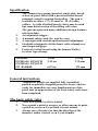
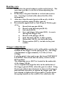
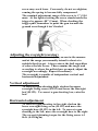
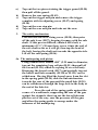
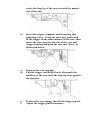
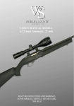
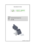
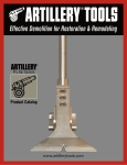
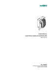
THE
WEBLEY
TEMPEST
AIR PISTOL
OWNER’S
MANUAL
Specification
1.
2.
3.
4.
5.
The Tempest is a spring-operated, single shot, break
action air pistol fitted with a precision-rifled barrel
primarily suited to waisted lead pellets. The gun is
available in either .177 (4.5 mm) or .22 (5.5 mm)
calibre. As with all rifled barrels, darts may be used
but some deterioration of the rifling will occur.
The gun incorporated many additional design features
which include:
An adjustable trigger.
A manual safety catch (i.e. selective use).
A rearsight with vertical and horizontal adjustment.
Stocksides designed to fit the hand, with a thumb rest
and chequered grips.
Positively locked barrel using the famous Webley
revolver type stirrup.
WEIGHT
OVERALL LENGTH
OVERALL LENGTH
OF BARREL
32ozs
9.12 ins
0.9 kg
232 mm
6.87 ins
175 mm
General instructions
Tempest air pistols are supplied fully assembled,
packed in specially designed protective boxes, and are
ready for immediate use once familiarisation of the
pistol and an appreciation of the basic safety rules have
been completed.
The basic safety rules
1.
2.
3.
Treat every pistol as if it is loaded.
Never point a pistol at anyone, or allow anyone to point
a pistol at you even if you think it is not loaded.
Always carry the pistol so that the direction of the
muzzle is under control, even if you stumble.
4.
5.
6.
Always be sure of your target and what lies behind it,
before you squeeze the trigger.
Never leave a loaded pistol unattended.
Beware of targets which tend to cause ricochets.
Keeping to these rules will ensure safe and enjoyable sport with
your new air pistol.
Operating instructions
The pistol is fitted with a manual safety mechanism
designed so that it is operative only when the gun is
cocked. Prior to cocking, therefore, the safe will be in
the “off” position, i.e. with the lever forwards toward
the muzzle end.
To cock the pistol hold it firmly by the grip in the right
hand then with the right thumb depress the barrel as
illustrated at A. Lift the barrel catch with the left hand
to take up the free movement then turn the hand over
so that the back of the hand is towards the body. Grip
the barrel firmly then rotate it until the sear is heard
and felt to engage. Keep the finger of the right hand
clear of the trigger whilst cocking the pistol.
It may be easier to cock the pistol with the left thumb
resting on the barrel (illustration B).
NB Never allow the barrel to spring back before the
sear is engaged, nor pull the trigger until the barrel is
returned and secured in its firing position.
If required, apply the safety catch by rotating the safety
lever points uppermost as illustrated at C.
To load
Insert a pellet into the breech end of the barrel until
flush with the end – do not leave the skirt of the pellet
protruding otherwise the joint washer (H.9) will
quickly be worn out. Close the barrel and squeeze
down until the stirrup clicks into engagement and is
seen to overlap the end of the barrel.
Point the gun towards the target and take a
comfortable stance for firing. If the safety catch is on,
to disengage it turn the lever anti-clockwise until it lies
roughly in line with the thumb rest (see illustration A).
Squeeze the trigger when ready to fire.
Routine care
1.
2.
3.
4.
Do not fire the pistol without a pellet in the barrel. The
only time you have to do this is when adjusting the
trigger pull.
Do not leave the pistol loaded or cocked when not in
use. Leaving it cocked with reduce the life of the
mainspring.
After use, wipe the metal parts with an oily cloth to
prevent corrosion, using Webley gun oil.
Occasionally apply three or four drops of Webley gun
oil to:
a) Barrel fulcrum pin (H.26)
b) Barrel catch fulcrum pin (H.18)
c) Safe shaft (H.55)
d) Sear and trigger fulcrums (H.51) Access is
through the trigger slot.
e) Barrel catch plunger (H.15)
f)
Link fulcrums (H.39), at three points.
g) Piston skirt (H.22), via slot in the body.
h) Piston washer (H.23), via hole in the joint
washer.
Trigger adjustment
Trigger pull adjustment can be achieved by varying the
tension on the trigger return spring (H.16). The range
of adjustment is approximately 3 to 5 lbs (1.36 to
2.27kg).
Cock the pistol, close and secure the barrel WITHOUT
LOADING, then check that the safety catch is in the
OFF position.
The adjusting screw (H.47) is located in the underside
of the trigger (H.46)
Access is gained through the hole in the underside of
the trigger guard (H.50), when the gun is cocked. Using
the key provided, turn clockwise to increase the trigger
pull and anti-clockwise to lighten the trigger pull. Do
not attempt to lighten the trigger pull to a point where
the spring tension on the screw is lost, otherwise the
screw may work loose. Conversely, do not overtighten,
causing the spring to become fully compressed.
The nominal adjustment range of the screw is .1” (2.54
mm). At the lightest setting the screw stands inside the
trigger by approx .08” (2 mm). When checking the
trigger pull, remember to point the gun towards the
ground even though it isn’t loaded.
Adjusting the rearsight (zeroing)
Fire six pellets as accurately as you can in the manner
and at the range you normally intend to shoot at a
suitable fixed target. Always aim at the bull regardless
of where the hits occur. Then examine the target and
according to where the pellets have grouped, adjust the
rearsight accordingly. Repeat if necessary.
The rearsight is capable of independent vertical and
horizontal adjustment.
Vertical adjustment
To correct a gun shooting high, slacken the upper
rearsight fixing screw (H.125) and lower the rearsight
leaf (H.123). To correct a gun shooting low, raise the
leaf.
Horizontal adjustment
To correct a gun shooting to the right, slacken the
lower rearsight fixing screw (H.125) and move the
rearsight base (H.122) to the left. To correct a gun
shooting to the left, move the rearsight base to the right.
The correct tightening torque for the fixing screw is 1
lb.ft. (0.138kg.m)
Servicing instructions
(for a qualified repairer)
Major overhaul or repair
The pistol need only be completely dismantled when it
is necessary to remove the piston assembly.
To replace a mainspring it is not necessary to
completely dismantle the gun, and section 4a covers the
procedure. It will normally become necessary to
change the mainspring only after the pistol has been
fired many thousands of times, indicated by a gradual
loss of pellet velocity.
To dismantle
FIRST ENSURE THAT THE PISTOL IS NOT COCKED, then
dismantle in the following sequence.
1.
Stocksides
Unscrew and remove one of the stockside fixing screws
H.65). The right and left-hand stocksides can be then
removed, one of them complete with its screw and stockside
nut (H.64).
2.
The sear trigger mechanism
Five of the long roll pins H.51) retaining the guard, sear and
trigger mechanism can be removed with an .089” (2.25 mm)
diameter drift.
Remove the pins and dismantle the components in the
following order.
a)
b)
c)
d)
e)
3.
Tap out the two pins retaining the trigger guard (H.50)
then pull off the guard.
Remove the sear spring (H.49)
Tap out the trigger axis pin and remove the trigger
complete with its adjusting screw (H.47) and spring
(H.16)
Tap out the sear stop pin.
Tap out the sear axis pin and take out the sear.
The safety mechanism
Unscrew the safe lever fixing screw (H.58), then prise
off the safe lever (H.57), keeping it square with the safe
shaft. If this proves difficult, obtain a 4BA bolt, a
minimum of 1¾” (30 mm) long, screw it into the end of
the safe shaft as far as it will go, then tap the head of
the bolt, forcing the shaft out towards the opposite side.
Lift off the safe spring (H.56).
4a The mainspring and piston
Using a small drift, ideally .089” (2.25 mm) in diameter,
tap out the remaining long roll pin (H.51) then pull off
the forend (H.126) which is a spring fit over the body.
Disengage the barrel catch (H.17) and partially tap out
the barrel and link assembly (H.120 or H.121) can be
withdrawn. Having lifted the barrel away from the slot
in the spring guide (H.24) slide the link mechanism
towards the rear of the gun until the small link (H.38)
can be withdrawn through the large hole in the body at
the end of the link slot.
Press the end of the spring guide against the
corner of a workbench, supporting the rear of the gun
against the stomach, then tap out the barrel fulcrum
pin the rest of the way, ease the pressure off the gun,
and allow the spring guide to emerge under the
influence of the mainspring.
PART No.
DESCRIPTION
No.OFF
H9
JOINT WASHER
H10
PASSAGE SCREW JOINT
1
1
H11
PASSAGE SCREW
1
H15
BARREL CATCH PLUNGER
1
H16
SPRING -TRIGGER & BRL CATCH
2
H17
BARREL CATCH
1
H18
BARREL CATCH FULCRUM PIN
1
H22
PISTON
1
H23
PISTON WASHER
1
H24
SPRING GUIDE
1
H25
LINK FULCRUM
1
H26
BARREL FULCRUM PIN
1
H27
MAINSPRING
1
H35
LONG LINK
1
H36
LINK SPRING
1
H37
INTERMEDIATE LINK
1
H38
SMALL LINK
1
H39
FULCRUM PIN SHORT
3
H46
TRIGGER - PRECISION CAST
1
H47
TRIGGER ADJUSTING SCREW
1
H48
SEAR
1
H49
SEAR SPRING
1
H50
TRIGGER GUARD
1
H51
FULCRUM PIN LONG
6
H55
SAFE SHAFT
1
H56
SAFE SPRING
1
H57
SAFE LEVER
1
WEBLEY TEMPEST SPARE PARTS LIST
PART No.
DESCRIPTION
No.OFF
H62
STOCKSIDE L.H
1
H63
STOCKSIDE R.H
1
H64
STOCKSIDE NUT
1
H65
STOCKSIDE FIXING SCREW
2
H116
BODY (NOT SUPPLIED AS A SPARE PART
1
H118
.177 BARREL & HOUSING ASSY
1
H119
.22 BARREL & HOUSING ASSY
1
H120
.177 BARREL & LINKS ASSY
1
H121
.22 BARREL & LINKS ASSY
1
H122
REARSIGHT BASE
1
H123
REARSIGHT LEAF
1
H124
REARSIGHT FIXING SCREW WASHER
2
H125
REARSIGHT FIXING SCREW
2
H126
FOREND
1
Remove the spring guide and mainspring, taking care
not to lose the link fulcrum (H.25).
4b. If it is necessary to remove the piston (H.22) insert a
small screwdriver through the slot on the top of the
body, engage the shouldered end of the piston and
gently tap out towards the open end of the body. It will
be necessary to change the position of the screwdriver
when the end of the slot in the body tube is reached. Reinsert the screwdriver into the sear groove of the piston
and continue tapping out until the piston can be
withdrawn. If the piston washer needs replacing,
carefully prise the old one off, taking care not to
damage the head of the piston (Note: the piston seal is
split in the same way as a conventional piston ring, to
aid assembly).
5.
The barrel and link assembly
Using a small drift, ideally .089” (2.25 mm) in diameter,
tap out the short roll pins (H.39). Do not lose the link
spring (H.36) located between the long link (H.35) and
the intermediate link (H.37).
6.
The barrel catch assembly
To remove the barrel catch (H.17), tap out the barrel
catch fulcrum pin (H.18), using an ½” (3 mm) diameter
drift. The barrel catch plunger (H.15) and its spring
(H.16) can now be removed.
7. The joint washer
Insert a small screwdriver down the hole in the joint
washer (H.9), tilt the screwdriver slightly and feel for
the bottom of the recess, then prise the joint washer
out.
Reassembly
To avoid difficulties in correctly positioning
components, reassemble in the reverse order of
dismantling. During reassembly the following points
should be adhered to, in order to achieve satisfactory
performance.
1.
The joint washer
When fitting a new joint washer, always make sure the
radius end is facing outwards - against the end of the
barrel - and that it is pushed right home into its recess.
2.
The barrel and link assembly
When assembling the link mechanism, make sure that
the long link, the intermediate link and the link spring
are correctly positioned relative to each other.
3.
The mainspring
When reassembling the mainspring, use the corner of a
workbench located in the slot in the spring guide to
provide stability when compressing the mainspring.
First, however, position the link fulcrum in its slot in
the spring guide and arrange this to be inline when
steering it into the end of the body slot. Push the body
of the gun over the spring guide until the barrel fulcrum
pin part way. Having slid the small link into the slot of
the body, position the lug of the barrel in the slot of
4.
5.
the spring guide, then push the barrel fulcrum pin right
home. Equalise the projection of the pin each side
before assembling the forend.
The safety mechanism
It is easier to assemble the safety mechanism before
assembling the trigger mechanism. When assembling
the safe shaft and lever, it is important to get their
relationship correct. To do this, hold the gun in a vice
with the barrel horizontal, then push the safety shaft
into position with its central flat uppermost. Next,
position the safety spring with its legs across the nearest
pair of flats of the square on the safety shaft. Push the
lever to engage the square on the shaft with the handle
of the lever pointing about 5° clockwise of
perpendicular. When the lever is home, its boss face is
just clear of the safe spring.
After assembling the safety lever fixing
screw, turn the safety lever anticlockwise to the fire
position before assembling the trigger mechanism.
The trigger mechanism
The accompanying illustration shows the parts
correctly fitted before the gun is cocked.
Reassemble in the following order
a) Drop the sear into its slot the correct way round
and pick up its location with a slave peg .089”
(2.25 mm) in diameter. Tap the roll pin through,
flush with the side of the body, letting the slave
peg be driven out against finger pressure, then
rotate the long leg of the sear towards the muzzle
end of the gun.
b)
Insert the trigger complete with its spring and
adjusting screw. Using the slave peg, locate and
fit the trigger in the same manner as the sear, then
insert the slave peg into the slot of the sear and
trigger housing and push the sear into ‘bent’, as
illustrated below.
c)
d)
Drive in the sear stop pin.
Pull the trigger and hold it back, then push the
small leg of the sear until the long leg rests against
the stop pin.
e)
f)
Position the sear spring, then fit the trigger guard.
Adjust the trigger pull if necessary.
WARRANTY REGISTRATION CARD
All Webley airguns are manufactured to the highest possible
standards, using the finest materials, to give faultless service. In the
unlikely event of there being a defect in material or workmanship, at
anytime, within the twelve months of the date of registration. Webley
undertake to repair or replace the shotgun (at Webley’s discretion).
Warranty is only valid for the original purchaser of the airgun and
cannot be transferred to subsequent owners.
Please note: The warranty will be invalidated if:
•
The airgun has been disassembled and incorrectly
assembled.
•
The airgun is found to have lubrication not recommended
by Webley.
•
The airgun has been fitted with non-standard parts.
•
The airgun has been misused or abused.
•
The warranty card is not returned within 28 days of
purchase.
Please note: The warranty does NOT cover:
•
O-rings, screws, seals, springs and stocks.
•
Any damage or faults caused by owner misuse or
accidental damage.
•
Carriage costs of the airgun to and from the service centre.
The warranty is in addition to your statutory rights in the
country of purchase. To register for the Warranty scheme
the warranty card must be completed and returned to
Webley within 28 days of purchase. Please retain your
sales receipt as proof of purchase.
Please fill in the correct details and post the card back to:
Webley & Scott. PO box 153, Chepstow, NP16 9AS.
If you have any problems with your Webley Tempest air pistol in
the first 12 months from original purchase you should contact the
dealer from where it was purchased.
If the pistol is out side the warranty period you can contact GSR:
www.gunservice.co.uk
Notes
Serial Number:……………………………………………….
Date of purchase:…………/………/……….
Model: WEBLEY TEMPEST
Calibre:………….
Where
purchased:…………………………………………………………
…………………………………..
Distributed in the UK and Ireland by:
Highland Outdoors.
www.highlandoutdoors.co.uk
E-mail: [email protected]
Tel: 01858 410 683
Fax: 01857 341 111