1
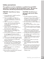
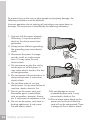
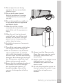
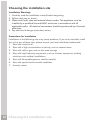
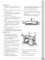
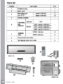
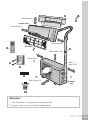
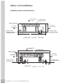
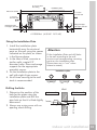
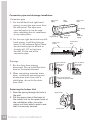
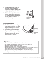
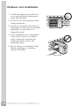
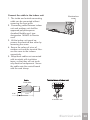
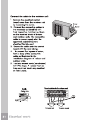
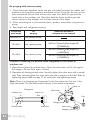
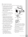
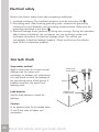
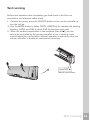
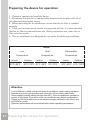
All about the Installation of your Split Type Room Air Conditioner Model(indoor/outdoor): FRS09PYW1/FRS09PYC1 FRS12PYW1/FRS12PYC1 FRS184YW2/FRS184YC2 FRS18PYW2/FRS18PYC2 FRS224YW2/FRS224YC2 FRS22PYW2/FRS22PYC2 www.frigidaire.com USA 1-866-942-1567 www.frigidaire.ca Canada 1-866-942-1567 Safety precautions This appliance must be installed by a qualified licensed HVAC technician in accordance with all applicable codes. All electrical connections should be performed by a licensed electrician. DANGER! Avoid Serious Injury or Death 1. Do not attempt to install the split air conditioner by yourself. 2. This air conditioner contains no user-serviceable parts. Always call an authorized Electrolux servicer for repairs. 3. When moving the air conditioner, always call an authorized Electrolux servicer for disconnection and re-installation. 4. Do not insert or place fingers or objects into the air discharge area in the front of the indoor unit. 5. Do not insert or place fingers or objects into the air discharge area in the outdoor unit. 6. Do not start or stop the air conditioner by unplugging the power cord or turning off the power at the electrical box. 7. Do not cut or damage the power cord. 8. If the power cord is damaged it should only be replaced by an authorized Electrolux servicer. 9. In the event of a malfunction (sparks, burning smell, etc.) immediately stop the operation, disconnect the power cord, and call an authorized Electrolux servicer. 10.Do not operate the air conditioners with wet hands 11.Do not pull on the power cord. 12.Do not drink any water that is drained from the air conditioners. CAUTION! Avoid Injury or damage to the unit or other property 1. Provide occasional ventilation during use. Do not direct airflow at fireplaces or other heat related sources as this could cause flare ups or make units run excessively. 2. Do not climb on or place objects on the outdoor unit. 3. Do not hang objects off the indoor unit. 4. Do not place containers containing water on the indoor and/or outdoor units. 5. Turn off the air conditioner at the power source when it will not be used for an extended period of time. 6. Periodically check the condition of the outdoor unit’s installation base for any damage. 7. Do not apply heavy pressure to the radiator fins of the indoor and/or outdoor units. 8. Operate the indoor unit with air filters in place. 9. Do not block or cover the intake grille, discharge area and outlet ports. 10.Ensure that any electrical/electronic equipment is one yard away from the indoor unit and outdoor unit. 11.Do not use or store flammable gases near the indoor and/or outdoor units. Safety precautions 04 To prevent injury to the user or other people and property damage, the following instructions must be followed. Incorrect operation due to ignoring of instructions may cause harm or damage. The seriousness is classified by the following indications. 1. Connect with the power properly. Otherwise, it may cause electric shock or fire due to excess heat generation. 2. Always ensure effective grounding. No grounding may cause electric shock. 3. Disconnect the power if strange sounds, smell, or smoke comes from it. It may cause fire and electric shock. 4. Do not operate or stop the unit by switching on or off the power. It may cause electric shock or fire due to heat generation. 5. Do not operate with wet hands or in damp environment. It may cause electric shock. 6. Do not allow water to run into electric parts. It may cause failure of machine, electric shock or fire. 7. Do not use the power cord near flammable gas or combustibles, such as gasoline, benzene, thinner, etc. It may cause an explosion or fire. 8. Do not use the power cord close to heating appliances. It may cause fire and electric shock. 05 Safety precautions 9.Do not damage or use an unspecified power cord. It may cause electric shock or fire. 10.Do not place heavy object on the power cord and ensure that the cord will not be compressed. There is danger of fire or electric shock. 11.Do not open the unit during operation. It may cause electric shock or injury. 12.Do not drink water drained from air conditioner. It contains contaminants and could make you sick. 13.Do not disassemble or modify unit. It may cause failure of appliance and electric shock. 14.When the air filter is to be removed, do not touch the metal parts of the unit. It may cause an injury. 15.When the unit is to be cleaned, switch off, and turn off the circuit breaker. Do not clean unit when power is on as it may cause fire, electric shock or injury. 16.Avoid direct exposure of occupants to air flow. 17.Turn off the main power switch when not using the unit for a long time. 18.The air conditioner may be dusted 20.Always insert the filters securely. with an oil free cloth, or washed Clean filter once every two weeks. with a cloth dampened in a solution Operation without filters may of warm water and mild dishwashing cause failure. detergent. Rinse thoroughly and wipe dry. Wring excess water from cloth 21.Always install circuit breaker and a before wiping around controls. dedicated power circuit. No installation may cause fire and 19.Ensure that the installation bracket of electric shock. the outdoor unit will not damage due to prolonged exposure. If 22.Do not place obstacles around airbracket damages, there will be inlets or inside of air-outlet. It may concern of damage due to falling cause failure of appliance or of unit. accident. Safety precautions 06 Choosing the installation site Installation Warnings 1. Carefully read the installation manual before beginning. 2. Follow each step as shown. 3. Observe all local, state and national electric codes. This appliance must be installed by a qualified licensed HVAC technician in accordance with all applicable codes. All electrical connections should be performed by a licensed electrician. 4. Pay attention to danger and safety notices Precautions for Installation Installation at the following sites may cause problems. If you must inevitably install the unit at one of these sites, please consult your local distributor beforehand: 1. Sites with machine oil. 2. Sites with a high concentration of salinity, such as coastal areas. 3. Sites with sulfuric gas, such as hot water springs. 4. Sites with high frequency equipment, such as wireless equipment, welding machines and medical installations. 5. Sites with flammable gases or volatile material. 6. Sites with special environmental conditions. 7. Laundry rooms. 07 Choosing the installation site 06 Indoor Unit inside wall, always leaving a space of 1. The unit must be installed at a site at least 6" between the top of the that does not obstruct the flow of air. indoor unit and the ceiling. 2. The site must support the weight of 8. The site must allow for the easy the indoor unit. removal of the connector pipe and 3. The site must be easily accessible drain hose. for maintenance and replacement 9. The unit must be installed at a site of the air filter. protected from direct sunlight. 4. The site must allow for the necessary space around the indoor More unit, as shown in the sideward than 6" figure. More 5. There should be at least 3 feet (1 than 6" meter) between the unit and radio or television devices. It is ideal More that the unit be installed at the than 6" center. 6. It must be far from fire, smoke or flammable gases. 7. We recommend the indoor unit to be installed as high up as possible on the Outdoor Unit 1. The outdoor unit must be installed at a convenient site that is not exposed to strong winds. The site should be dry and well ventilated. 3. There must not be the possibility of increased noise and vibration at the site. 5. The site cannot have any leakage of flammable gases. More than 1' 06 2. The site must support the weight of the outdoor unit and allow for vertical installation. 4. The unit must be installed at a site where the noise produced by its operation and air discharge does not disturb the neighbors or animals. More than 1.65' More than 1' More than 6.6' More than 1.65' 6. The site must provide enough space around the unit, as shown in the figure. 7. Children must not be able to access the installation site. Choosing the installation site 08 1 More than 6" 3 Indoor unit More than 6" 6 More than 6" Air filter 4 5 More than 1.65' More than 1' A 8 More than 1.65' 7 6 B More than 6.6' C Outdoor unit 2 Attention 1. This illustration is for explanation purposes only. 2. Copper tubes must be insulated independently Parts list 10 Indoor unit installation Installation plates and dimensions 6" or more from the ceiling Installation plate Refrigerant pipe hole (right) Ø 2.56" B 4.21" 6" or more from the wall 4.21" Indoor unit outline Refrigerant pipe hole (right) Ø 2.56" 3.39" 3.39" 6" or more from the wall A < 12000 Btu's (A:33.31" B:10.83") 6" or more from the ceiling Installation plate A Indoor unit outline 6" or more from the wall B 6" or more from the wall Refrigerant pipe hole (right) Ø 2.56" 1.58'' Refrigerant pipe hole (right) Ø 2.56" 1.58'' 7.91'' 5.31'' =18000 Btu's (A:36.97" B:11.73") 11 Indoor unit installation 6" or more from the ceiling A Installation plate Indoor unit outline 6" or more from the wall B 6" or more from the wall 1.97'' 1.97'' Refrigerant pipe hole (right) Ø 2.56" 3.94'' Refrigerant pipe hole (right) Ø 2.56" 4.88'' =21500 Btu's (A:39.69" B:12.40") Fixing the Installation Plate 1. Install the installation plate horizontally over the structural parts on the wall using the spaces indicated on the plate, as shown in the figures above. 2. In the case of tiled, concrete or similar walls, create 0.2" diameter holes. Place anchorage supports for the appropriate assembly screws. 3. Fix the installation plate to the wall with eight A type screws. 4. At all times securing to the wall studs is recommended. Attention Fit the Installation Plate and drill holes in the wall according to the wall structure and corresponding mounting points on the installation plate (Dimensions are in “mm” unless otherwise stated). Installation plate Drilling the Hole 2. Always use a pipe cover with an opening when drilling. Indoor unit Outdoor unit 0.2"-0. 28" 1. Determine the position of the hole for the pipes using the installation plate and drill the pipe hole so that it is tilted slightly downward. Wall Indoor unit installation 12 Connective pipe and drainage installation Connective pipe 1. For the left-hand and right-hand piping, remove the pipe cover from the side panel. The pipe cover must be kept as it may be used when relocating the air conditioner to any other place. Pipe cover (right) Drainage 1. Run the drain hose sloping downward. Do not install the drain hose as illustrated sideward. 2. When connecting extension drain hose, insulate the connecting part of extension drain hose with a shield pipe, do not let the drain hose slack. Rear right piping 13 Indoor unit installation Rear left piping Connective pipe 1.69" Indoor unit outline Do not block water flow by a rise. Do not put the end of drain hose into water. Fastening the Indoor Unit 1. Pass the piping through the hole in the wall. 2. Put the upper claw at the back of the indoor unit on the upper hook of the installation plate, move the indoor unit from side to side to see that it is securely hooked. Pipe cover (left) Left piping Right piping 2. For the rear-right-hand and rear-lefthand piping, install the piping as shown in the sideward figure. Bend the connective pipe to be laid at a height of 1.69" or less from the wall. Fix the end of the connective pipe. Pipe holder Upper hook Lower hook Do not block water flow by a rise. 3. Piping can easily be made by lifting the indoor unit with a cushioning material between the indoor unit and the wall. Get it out after finish piping. 4. Push the lower part of the indoor unit up on the wall, Then move the indoor unit from side to side, up and down to check if it is hooked securely. Piping and wrapping 1. Bundle the tubing, connecting cable, and drain hose with tape securely and evenly as shown in the sideward figure. 2. Because the condensed water from rear of the indoor unit is gathered in ponding box and is piped out of room, do not put anything else in the box. Cushioning material Indoor unit Cable connection Ponding box Pipe room Connective pipe Drain hose Wrapping belt Attention 1. 2. 3. 4. 5. Connect the indoor unit first, then the outdoor unit. Do not allow the piping to let out from the back of the indoor unit. Be careful not to let the drain hose slack. Both of the auxiliary piping should be heat insulation. Be sure that the drain hose is located at the lowest side of the bundle. Locating at the upper side may cause drain pan to overflow inside the unit. 6. Never intercross nor intertwist the power wire with any other wiring. 7. Run the drain hose sloped downward to drain out the condensed water smoothly. Indoor unit installation 14 Outdoor unit installation 1. Install the outdoor part of the unit on a rigid surface to avoid excess noise and vibration. 2. Direct the air vent toward an area without obstacles. 3. Install the unit at the site where it is exposed to as little wind as possible, especially in areas where it is frequently windy. 4. If the installation site is exposed to heavy winds, such as in coastal areas, place the unit along the widest part of the wall or use protective plates. 5. Be sure there is no obstacle which blocks radiating air, including schrubs or bushes. Strong wind 15 Outdoor unit installation $ Settlement of outdoor unit Anchor the outdoor unit tightly and horizontally on a concrete or rigid mount with a bolt and nut 0.39" or % 0.32" diameter (Purchased separately). Air inlet Air inlet Air outlet Outdoor unit dimension ft) A ft(WxHxD) B( ft) [ [ 1' [ [ [ [ ' Condensate drainage of outdoor unit (no for cooling only) The condensate and defrosting water formd during heating in the outdoor unit can be properly discharged by drainage pipe . Installation method:Insert the drain connection into one of the Ø 25 holes of the chassis and then connect drainage pipe with drain nozzle. Insert drainage plugs into the other holes (Only for 12000Btu's). < 12000 Drain connection %WX V Btu's Chassis Drain connection Chassis Drainage Plug Outdoor unit installation 16 Refrigerant piping connection Unit comes with 16.4' tubing bundle. It is not recommended to cut. If too long, loop for excess. Note: Keep original bend so not kinking of the tube occurs. Flaring work Main cause for refrigerant leakage is due to defect in the flaring work. Pipe Carry out correct flaring work using the following procedure: 1. Cut the pipes and the cable. A) Use the piping kit accessory or pipes purchased locally. B) Measure the distance between the indoor and the outdoor unit. C) Cut the pipes a little longer than the measured distance. D) Cut the cable 4.9ft longer than the pipe length. 2. Burr removal A) Completely remove all burrs from the cut cross section of pipe/tube. B) Put the end of the copper tube/pipe in a downward direction as you remove burrs in order to avoid dropping burrs into the tubing. 3. Put nut on. Remove flare nuts attached to indoor and outdoor unit, then put them on pipe/tube having completed burr removal.(It is not possible to put them on after flaring work) 17 Refrigerant piping connection Wrong Correct Oblique Roughness Burr Pipe Reamer Point down Flare nut Cooper tube 4. Flaring work. Firmly hold copper pipe in a die in the dimension shown in the table below. OUTER DIAMETER (inch) Bar Copper pipe Handle A (inch) Max. Min. 1/4 0.051 0.028 3/8 0.063 0.039 1/2 0.071 0.039 5/8 0.095 0.087 Connection Adjustment 1. Align the pipes to be connected. 2. Screw the flare nut with your fingers, and then tighten it with a spanner and torque wrench, as shown in the following figure. Indoor unit tubing OUTER DIAMETER (inch) Flare nut Yoke Red arrow mark Clamp handle Caution: Excessive twisting may break the nut, depending on the installation conditions. Pipings TIGHTENING TORQUE (lbf.in) ADDITIONAL TIGHTENING TORQUE (lbf.in) 1/4 139 174 3/8 260 304 1/2 434 477 5/8 651 694 Refrigerant piping connection 18 Power voltage should meet the requirements in the following table. 3. Over current protection and circuit disconnect should meet the requirements in the following table and the applicable local and national electrical codes. Electrical Data Table Capacity (BTU) 9K 12K 18K 21.5K System Voltage Volts-Ph.Freq Operating Voltage Compressor (Min/Max) RLA LRA FLA HP Output Watts Volts FLA HP Output Watts 16.03 26 0.17 0.04 30 115V-AC 0.38 0.03 ǂ 103/127 ǂ 115-1-60 103/127 ǂ 208/230-1-60 187/253 ǂ 208/230-1-60 187/253 115-1-60 Outdoor Fan Indoor Fan MIN. Circuit Ampacity (MCA) Max. Fuse/Circuit Breaker Amps(MOCP) 20 22 35 17.53 26 0.17 0.04 30 115V-AC 0.38 0.03 20 23 40 11.54 41 0.62 0.08 60 208/230V-AC 0.25 0.03 20 16 25 11.71 41 0.9 0.12 90 208/230V-AC 0.45 0.05 35 16 25 Connecting (Power and Control Cable) The main power is supplied to the outdoor unit. The field supplied connecting cable from the outdoor unit to indoor unit consists of four wires and provides the power for the indoor unit as well as the communication signal and ground between the outdoor and indoor unit. Two wires are high voltage AC power, one is low voltage DC signal and one is a ground wire. Consult local building codes, NEC (National Electrical Code) or CEC (Canadian Electrical Code) for special requirements. Connect the cable to the indoor unit Electrical box cover 1. The inside and outside connecting cable can be connected without removing the front grille. 2. Connecting cable between indoor unit and outdoor unit shall be approved polychloroprene sheathed flexible cord, type designation 16AWG or heavier cord. 3. Lift the indoor unit panel up, remove the electrical box cover by loosening the screw. 4. Ensure the colour of wires of outdoor unit and the terminal Nos. are the same to the indoors respectively. 5. Wrap those cables not connected with terminals with insulation tapes, so that they will not touch any electrical components. Secure the cable onto the control board with the cord clamp. Cable Terminal block of indoor unit Code wire N(1) 2 0.39" 3 1.57" To Outdoor Unit Electrical work 20 1. Caution After the confirmation of the above conditions, prepare the wiring as follows: 1. Never fail to have an individual power circuit specifically for the air conditioner. As for the method of wiring, be guided by the circuit diagram posted on the inside of control cover. 2. The screws which fasten the wiring in the casing of electrical fittings are liable to come loose from vibrations to which the unit is subjected during the course of transportation. Check them and make sure that they are all tightly fastened. (If they are loose, it could cause burn-out of the wires.) 3. Specification of power source. 4. Confirm that electrical capacity is sufficient. 5. See to that the starting voltage is maintained at more than 90 percent of the rated voltage marked on the name plate. 6. Confirm that the cable thickness is as specified in the power source specification. 7. Always install an earth leakage circuit breaker in a wet or moist area. 8. The following would be caused by voltage drop: vibration of a magnetic switch, which will damage the contact point, fuse breaking, disturbance of the normal function of the overload protector. 9. The means for disconnection from a power supply shall be incorporated in the fixed wiring and have an air gap contact separation of at least 1/8 inch in each active (phase) conductors. Air purging Air and moisture in the refrigeration system have undesirable effects as indicated below: 1. Pressure in the system rises. 5. Water may lead to corrosion of parts in the refrigeration system. 2. Operating current rises. Therefore, the indoor unit and tubing 3. Cooling or heating(only for between the indoor and outdoor unit models with heating function) must apply leakage test and be evacuated efficiency drops. 4. Moisture in the refrigerant circuit to remove any noncondensables and moisture from the system. may freeze and block capillary tubing. Electrical work and air purging 22 Air purging with vacuum pump 1. Check that each tube(both liquid and gas side tubes) between the indoor and outdoor units have been properly connected and all wiring for the test run has been completed. Remove the service valve caps from both the gas and the liquid side on the outdoor unit. Note that both the liquid and the gas side service valves on the outdoor unit are kept closed at this stage. 2. When relocating the unit to another place, perform evacuation using vacuum pump. 3. Pipe length and refrigerant amount: Additional amount of refrigerant to be charged Air purging Connective pipe length Less than 25' Use vacuum pump. 25'~65.6' R410a: 0.32ozs/ft (Pipe length-25') (<12000 Btu's) Use vacuum pump. R410a: 0.22ozs/ft (Pipe length-25') (=18000 Btu's) Use vacuum pump. 25'~98.4' R410a: 0.32ozs/ft (Pipe length-25') (=21500 Btu's) Caution in handling the packed valve integrated in the outlets of outdoor unit. 1. Operation of opening packed valve: Open the valve stem until it hits against the stopper. Do not try to open it further. 2. Operation of closing packed valve: Securely tighten the valve stem with a special tool. Then securely tighten the valve stem cap with a spanner or the like. Refer to tightening torque table in page 17 for valve stem cap tightening torque Note: There is a charging port integrated in the low side outlet, but not in the high side outlet. The low side outlet is shown in the sketch map below. Flare nut Refrigerant Outdoor unit A Valve body Indoor unit Gas C Cap D B Packed valve Charge port Half union Valve stem Stopper 23 Air purging When using the vacuum pump For method of using a manifold valve, refer to its operation manual. 1. Completely tighten the flare nuts at connection point A, B, C and D. Connect valve core removal tool to the charging port, then connect vacuum hose to valve core tool. Open the schrader valve. Note: The schrader valve is inside the charging port. 2. Connect the other charge hose of manifold valve to the vacuum pump. 3. Fully open the handle Lo of the manifold valve. 4. Operate the vacuum pump to evacuate. After starting evacuation, slightly loose the flare nut of the Lo valve on the gas pipe side and check if the air is entering (Operation noise of the vacuum pump changes and a compound meter indicates 0 instead of minus), then tighten the flare nut. The procedure verifies if there are blocks inside the tubes. 5. Make evacuation for 15 minutes or more and check that the compound meter indicates 5 -7.6 x 10 MicronsHg (-1x10 Pa). After the evacuation is completed, fully close the handle Lo of the manifold valve and stop the operation of the vacuum pump. 6. Turn the stem of the packed valve B about 45 o counterclockwise for 6~7 seconds after the gas comes out, then tighten the flare nut again. Make sure the pressure Indoor unit Outdoor unit Manifold valve -76cm/Hg Handle Lo Charge hose Handle Hi Charge hose Vacuum pump display in the pressure indicator is a little higher than the atmosphere pressure. This procedure verifies if the refrigerant goes through the tubes correctly. 7. Close the schrader valve, then remove the valve core tool. Replace the charging port cap. 8. Fully open the packed valve stems B and A. 9. Securely tighten the cap of the packed valve. Air purging 24 Electrical safety Perform the electric safety check after completing installation: 1. Insulated resistance: The insulated resistance must be more than 2M . 2. Grounding work: After finishing grounding work, measure the grounding resistance by visual detection and grounding resistance tester. Make sure the grounding resistance is less than 4 . 3. Electrical leakage check (performing during test running): During test operation after finishing installation, the serviceman can use the electric probe and multimeter to perform the electrical leakage check. Turn off the unit immediately if electrical leakage happens. Check and find out the solution ways till the unit operates properly. Gas leak check Soap water method Apply a soap water or a liquid neutral detergent on the indoor unit connection or outdoor unit connections by a soft brush to check for leakage of the connecting points of the piping. If bubbles come out, the pipes have leakage point. Leak detector Use the leak detector to check for leakage. indoor unit check point Cover Outdoor unit check point Caution A: Lo packed valve, B: Hi packed valve C and D are ends of indoor unit connection. 25 Electrical safety and gas leak check Test running Perform test operation after completing gas leak check at the flare nut connections and electrical safety check. 1. Connect the power, press the ON/OFF button on the remote controller to turn the unit on. 2. Use the MODE button to select COOL, HEAT(Only for models with heating function), AUTO and FAN to check if all the functions work well. 3. When the ambient temperature is too low(lower than 63 o F), the unit cannot be controlled by the remote controller to run in cooling mode, manual operation can be taken. Manual operation is used only when the remote controller is disable or maintenance necessary. Auto/OFF Manual control button Test running 26 Preparing the device for operation 1. Contact a specialist to install the device. 2. Guarantee that the unit is appropriately fastened and complies with all of the aforementioned safety norms. 3. Before operating the air conditioner, ensure that the air filter is installed correctly. 4. If the unit has been out of use for a long period of time, it is recommended that the air filter be cleaned before use. During continuous use, clean the air filter every two weeks. 5. This air conditioner was designed for use under the following conditions: MODE Cool Heat * Dehumidifier Temperature Temperature Temperature Indoor 61°F~86°F Outdoor Indoor 41°F~115°F 61°F~86°F Outdoor 5°F~75°F Indoor Outdoor 61°F~86°F 41°F~115°F * only for models with heating function Attention If air conditioner is used outside of the above conditions, certain safety protection features may come into operation and cause the unit to function abnormally. Room relative humidity should be less than 80%. If the air conditioner operates in excess of this figure, the surface of the air conditioner may attract condensation. Please set the horizontal louver to its maximum angle (vertically to the floor), and set HIGH fan mode. Optimum performance will be achieved within these operating temperature. 27 Preparing the device for operation