1
User Guide for the
Silence Sense Sr.
Silence Sense Detector
and Pager / Dialer
Version 1.0
DM Engineering
2174 Chandler St.
Camarillo, CA 93010
805-987-7881
www.DMEngineering.com
Theory of Operation
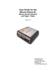
The Silence Sense Sr. is a microprocessor-based device that senses the
presence of audio from a single ended input over a wide range of input
levels. A user adjustable input control and LED indicator are used to set
the input sensitivity. When the audio input ceases for a predetermined
user selectable period, (0-60 seconds standard or approximately 15
seconds to 3 ½ minutes, by special order), a pre determined phone
number and tone or paging sequence is transmitted over a standard
telephone line. If set to “chain”, a second phone number and tone or
paging sequence will be processed automatically. Re-application of audio
automatically resets the device. If the “chain” feature is not used, the
Pager/Dialer section has an additional input that may be connected by the
user for any purpose of their choice. A contact closure will activate this
second input channel. Power indication is indicated by a green LED,
which turns amber during dialing and paging sequences. Programming is
accomplished using the “HyperTerminal” program supplied with Microsoft
Windows 95 and 98. Memory for the programmed codes is saved in nonvolatile e²prom. Power for the device is supplied by a “wall wart” power
supply and battery back up is provided to assure operation when the
power fails.
Connections
1. Audio input…A single ended audio source is attached to the supplied RCA
male connector. This connector is to be inserted in the RCA female
connector on the end of the Silence Sense Sr.
2. Phone Line…A standard RJ11 phone line connection is made with the
supplied 6’ cable.
3. Power input…Connect the “wall wart” 12-volt DC output connector to the
power input jack on the unit. Plug the “wall wart” into a convenient
117VAC outlet.
4. Battery back up…Remove the rear battery compartment door by pressing
down and outward on the latch. Locate the battery that was shipped with
the unit and remove the protective terminal cover from the battery.
Connect the battery to the snap on battery connector in the compartment
and replace the door.
5. Programming input…A DB9 female connector is provided for interface
with a computer serial port using the supplied cable. See Programming
instructions.
6. Chain connector…By placing the supplied red shorting jumper across the
2 pins on the chaining circuit, the device will automatically dial both
numbers and send both codes programmed into the device in the same
sequence that the particular inputs were activated.
7. Activation inputs…The left most input screw connector is dedicated to the
Silence Sense function, but may be used for another function if desired by
removing the wire connected to it. This will disable the Silence Sense
function entirely. The second input and “common” screw connectors may
be used for any contact closure application the user desires, and will
activate the unit with the phone number and codes programmed into the
second channel of memory.
Setup and programming
1. Connect the DB-9 cable to the computer serial port of your choice using
the supplied cable.
2. Disconnect all alarm inputs, including the blue wire to the SS input screw
terminal, telephone cable and 9V battery from the Pager-Dialer if
connected.
3. Connect the AC power adapter to the power input jack of the Pager-Dialer
and connect the power adapter to the wall socket.
4. Power up your computer and using Microsoft Windows 98™ or “95”. On
the desktop go to Start, Programs, Accessories, Communications,
HyperTerminal. Select HyperTerminal and enter whatever name and
select an icon at the prompt that you desire to record the programming
sequence for this device. Click OK.
5. In the connect to dropdown box click on Direct to COM 1 or Direct to
COM 2, indicating whichever serial port you are connecting to. Click OK.
6. In the Com Properties / Port Settings window, set the Bits per second
to 9600, the Data bits to 8, the Parity to None, the Stop bits to 1, and
Flow control to None. Click OK to close the Com Properties window.
7. Click File, Properties. Click on the Settings tab, then the ASCII Setup
box. Check Echo typed characters locally and Append line feeds to
incoming line ends. Check OK twice. Leave any other checked boxes
as they are.
8. You are now in Terminal mode. Turn the Caps Lock on your keyboard
on.
9. Type D1 and then type the phone or pager number to dial for the first alert
input port, followed by Enter. Your entries will NOT echo on the terminal
screen. Do not put any spaces, dots or dashes or other characters in the
string. Valid characters are 0 through 9, *, #, and W. A “W” will insert a
2.5 second delay between dialed characters and is considered a character
in itself. A maximum of 15 characters are allowed for phone numbers and
15 characters maximum for alert codes for each input.
10. Now type D1 followed by Enter. The terminal screen should now verify
your input by displaying the phone or pager number entered. If you make
an error at any time just press Enter to exit the inputting string and retype
the D1 or the appropriate programming command followed by Enter again
to reprogram. This is true for any of the programming strings to follow.
11. Type P1 followed by Enter, and type the code you want to use for the
pager display or telephone audible. It is mandatory that the last
character in a pager alert code be the # symbol of the paging
function will not work. Telephone audibles may end with any character.
12. Type P1 and enter to verify the alert code you entered.
13. Repeat steps 9-12 for the 2nd alert input pager or telephone number and
code number, using D2 and P2 instead of D1 and P1 to program this
input.
14. Your programming setup is now complete. Disconnect the Power and
programming cable from the Pager-Dialer, and shut down HyperTerminal
on your computer. You will be prompted to save the session and it is
advisable to do so in the event you wish to reprogram the device without
having to retype all of the setup information
15. If you wish to have both alert inputs dial both programmed numbers in
case either or both inputs are activated, place the red “Chain” jumper on
both terminals where provided. To have each alert input dial separately
without transmission with the other programmed information, remove or
place the “Chain” jumper only on one terminal.
16. Adjust the audio gain control to maximum or fully clockwise position, and
the duration control to the minimum or counter clockwise position.
17. You may now reconnect the alert input connection(s), DC power cable,
telephone modular cable and back-up battery to the Pager-Dialer.
Remember that the back-up battery is in use whenever the DC power
connection is removed or whenever there is no AC power from the wall to
the AC power adapter. If the unit is not in use, disconnect the back-up
battery.
18. With audio present at the input, adjust the gain adjust control in the
counter clockwise direction until the yellow LED starts to flicker during low
audio passages. Depending on your programming, this level may need to
be readjusted for reliable audio detection later.
19. Adjust the duration set control to the desired timeout period. Fully
counter-clockwise is 5 seconds, mid-setting is 30 seconds, and fully
clockwise is 60 seconds, or approximately 15 seconds, 1 ¾ minutes, and
3 ½ minutes respectively on special order units. You may set the control
to any position desired. Note that after the adjustment is made the power
and battery backup must be momentarily be removed and reapplied to
reset the timing microprocessor. This is true any time the duration set
adjustment is changed. The power LED will signify when the timeout
period has been reached.
Operation and test
To test the Silence Sense Sr., remove the audio input RCA connector and
wait for the power LED to show activation. This will be the actual delay
time, and may be reset at will. Remember to momentarily remove the
power to reset the microprocessor each time this adjustment is changed.
To test the battery back-up operation simply disconnect the external DC
power. The Silence Sense Sr. should continue to function normally.
That’s it… the Silence Sense Sr. is now ready and waiting to monitor your
audio.
Hints
Most programming has pauses from time to time that may last for 30
seconds or more, especially if you are broadcasting Sunday morning
church services. Experience has taught that 45-60 seconds or more is the
best selection if you don’t want to receive false alarms. Also, take time in
setting the input levels. Wait and watch the yellow LED through different
types of programming or selections of music and speech to assure that
the sensitivity is set correctly.
Specifications
• Audio Input: Impedance is 10K ohms minimum, single ended, RCA
female connector
• Audio Input Level: -20 to +10 dbm., input adjustable
• Silence Detect Time: 5-60 seconds, (15-210 seconds, approx., by
special order), user adjustable
• Activation input: N.O. Contact closure or pull down (+5VDC pull ups
supplied) between input and common screw terminals.
• Output: DTMF supplied by an RJ11 connector and cable.
• Programming: Serial connection using “HyperTerminal” application
program as supplied with Microsoft Windows 95 or 98 or equivalent.
• Power Requirements: Supplied adapter, 115 VAC to 12 VDC, 100-200
ma.
• Battery Back-up Requirements: 9 VDC alkaline battery, NEDA 1604A
(supplied)
• Size: 5.1 x 5.3 x 1.7
• Shipping Weight: Approximately 2 lbs.