1
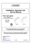
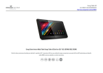
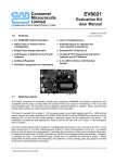
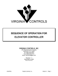
7998600 Rev. 4
The material in this manual is for information purposes only. The contents and the product it describes
are subject to change without notice. Thermo Electron Corporation makes no representations or
warranties with respect to this manual. In no event shall Thermo be held liable for any damages, direct
or incidental, arising out of or related to the use of this manual.
MANUAL NO. 7998600
4
3
2
---1
0
FR-1789
22216
22179
REV
ECR/ECN
21605
6/27/05
3/22/04
2/24/04
8/21/03
8/13/03
6/27/03
5/29/03
3/21/03
DATE
Revised VRP troubleshooting section for Release 3
Added 120V 23 cu. ft. units
Revised electrical schematic, start capacitor part number
Door gap, high stage revisions
Revised compressor information page B-1
Revisions per A. Thomas
Wrong power alarm modifications
New manual
aks
aks
aks
aks
aks
aks
aks
aks
DESCRIPTION
BY
ii
Table of Contents
Section 4 -Hidden Functions
4.1 Hidden Test ........................................... 4-1
4.2 Hidden Calibration ................................ 4-2
Section 1 – General Operation
1.1 Initial Start Up...................................... 1-1
1.2 Equipment Explanation......................... 1-1
1.3 Operating Pressure
“High and low stage systems”............... 1-1
Appendix A - Glossary
Glossary of terms ........................................ A-1
Section 2 – Troubleshooting Charts
2.1 Probe 1,2,3, and 4 failure alarm
(Single) ............................................... 2-1
2.2 Probe 1,2,3, and 4 failure alarm
(All probes) .......................................... 2-1
2.3 Unit will not communicate with alarm
system ................................................. 2-2
2.4 Display/Keyboard not functioning ....... 2-3
2.5 Door ajar alarm.................................... 2-4
2.6 No door access .................................... 2-5
2.7 Low battery alarm................................ 2-6
2.8 Noise ................................................... 2-6
2.9 Hot condenser alarm ............................ 2-7
2.10 High stage system failure alarm ........... 2-8
2.11 Power failure alarm.............................. 2-9
2.12 Wrong power ....................................... 2-10
2.13 Low Temperature................................. 2-10
2.14 High temperature alarm or system not
maintaining temperature ...................... 2-11
2.15 Troubleshoot compressor ..................... 2-13
2.16 Voltage Compensation Failure ............. 2-14
Appendix B
Compressor Information .............................. B-1
Section 3 – Charts and Schematics
3.1 Analog Output Reference Table ............. 3-1
3.2 RTD Temperature vs. Resistance ........... 3-2
3.3 Pressures vs. Cabinet Temperature......... 3-3
3.4 Refrigeration Schematics ....................... 3-4
3.5 Electrical Schematics ............................ 3-6
3.6 Micro Board .......................................... 3-8
3.7 High Voltage Board ............................... 3-8
iii
General Operation
1.1 Initial Start Up
1. Power Switch on.
2. Cabinet temperature 0.5°C or warmer than set point.
3. Fans 1 and 2 turn ON.
4. High stage compressor turns ON, after ten seconds delay.
5. Low stage compressor turns ON when:
A. Thirty seconds after high stage starts and heat exchanger probe reads
–41°C or colder or
B. Five minutes after high stage starts and heat exchanger probe reads
between –33°C to –40°C.
If heat exchanger probe warms-up to –20°C or warmer, the low stage
compressor shuts down until either condition 5A or 5B is met. After thirty
minutes, if condition 5A or 5B is not met, the high stage system failure will be
activated.
6. Once the cabinet temperature reaches –50°C, the*expansion tank solenoid is
opened (de-energized). The vacuum relief heater and mullion heater on double
door units, are energized and operate continuously until the cabinet is warmer
than –50°C.
7. Set point achieved, fans and compressors cycle off.
8. Steps 2 though 7 repeat (cycle).
*Items
or functions unique to this system
1.2 Expansion Tank Assembly and Solenoid Valve
Location: Suction side of low stage system.
Purpose:
Tank assembly increases low stage system refrigeration
capacity. Prevents excessive low stage pressures at
temperatures warmer than –50°.
Operation: The tank assembly solenoid valve is normally open. The
solenoid valve is energized (closed) when the control probe
senses temperature warmer than –50°C. The solenoid valve is
de-energized (open) when the control probe senses
temperature colder than –50°C.
1.3 Operating Pressure “High and low stage systems”
The suction side pressure for both systems typically runs in a vacuum. Prior to
opening a system for a pressure reading, always purge your lines according to the
manufacturer’s recommended procedure. For further information, call Thermo Forma
Service Department.
230 Volt Freezers
Only the compressors require 230 volts. The remaining high voltage components
operate using 115 volts.
1-1
2.1 Symptom: Probe 1, 2, 3, or 4 Failure Alarm - SINGLE PROBE FAILURES
Order
1
2
3
Possible Cause
Verification
Action
Unplugged.
Re-seat connector.
Re-seat all connections.
Not fully seated
Verify wires are fully seated in connectors and
connectors are seated together
Replace probe if necessary.
Short.
Open.
Display reads 99. Verify probe resistance. See
Temperature vs. Resistance Chart (Page 3-2).
Replace probe.
Wrong value.
Verify probe resistance. See Temperature vs.
Resistance Chart (Page 3-2).
Replace probe.
Micro board.
Temporarily switch suspect probe with control or
heat exchanger probe.
If the same error exists, replace micro board.
Probe
Bad probe
2.2 Symptom: Probe 1, 2, 3, and 4 Failure Alarm – (ALL PROBES FAIL)
Order
1
Possible Cause
Verification
Control probe not installed.
Re-seat connector.
Verify wires are fully seated in connectors and
connectors are seated together.
Startup only.
2
Bad control probe
Short.
Open.
Wrong value.
3
4
Action
Display reads 99. Bad control probe will also
cause a high temperature alarm and lock both
compressors on.
Verify probe resistance with Temperature vs.
Resistance Chart (page 3-2).
Reinitialize (re-start) unit.
Reseat all connections.
Replace probe if necessary.
Replace probe.
Micro board.
Temporarily switch control probe with heat
exchanger probe.
If the same error exists, replace micro board.
Micro board EEPROM
Problem still exists after re-initializing unit.
Re-initialize eeprom in test mode. If problem
remains, replace the micro board. Note: all
calibration, set points and configuration are set to
default.
2-1
2.3 Symptom: Unit will not communicate with alarm system (Remote Alarm Contacts/Analog
System/Serial communication)
Order
1
2
3
Possible Cause
Verification
Action
Remote Alarm Contacts
Check that all connections are tight and properly
wired. Missing wires?
Tighten and / or correct wiring.
Measure continuity of alarm contacts between
pins 6 & 7 and 6 & 8 while toggling in test mode
(pin 6 is common).
Replace micro board if contacts do not change
state.
Verify the setting is correct in hidden calibration
and corresponds to the dip switch settings on the
micro board per the electrical schematic.
Measure output. Compare with Analog Output
Reference Table (page 3-1).
Make changes so the dip switch settings and hidden
calibration settings match.
Check that all connections are tight and properly
wired. Missing wires?
Tighten and / or correct wiring.
Verify address is correct in configuration menu
and matches the 1535 address.
Change so that the unit address of the freezer
matches the 1535 address.
Verify the setting is correct in hidden calibration
and corresponds to the dip switch settings on the
micro board per the electrical schematic.
Check that all connections are tight and properly
wired. Missing wires?
Tighten and / or correct wiring.
Verify that the cable is a DB9 (straight through)
extension cable.
Make changes so that the dip switch settings and
hidden calibration settings match.
Analog Output
Serial Communication
2-2
Call the factory service department 888-213-1790.
See section 4.2.p Analog Calibration (page 4-3).
Tighten and / or correct wiring.
Replace cable if necessary.
2.4 Symptom: Display / Keyboard Not Functioning
Order
1
2
3
4
5
Possible Cause
Verification
Action
Turned battery on before AC power is
applied.
(initial start up issue only)
No AC power and no battery power.
Ask customer/end user.
Turn unit power off. Turn battery off. Reapply AC power
before the battery is turned on.
Verify supply AC voltage is present.
Supply correct line voltage.
+14VDC on switching power supply.
If not, replace switching supply.
+14VDC on micro board at connector
labeled DC power from HV board (pins 1
and 6).
Is unit operating (fans, compressors)?
Check connector seating on ribbon cables. Replace if
required.
Micro board Micro LED LD1 on micro board not
functioning.
Micro board - Micro LED LD1
functioning / no display LED LD2.
If no, replace micro board.
If yes, continue to step 4.
Turn unit off, then turn unit back on.
Miscellaneous characters displayed. Replace display board.
Check connection of 25 pin D sub cable
at both ends.
Waiting Comm is displayed. Replace micro and/or display as
needed.
Display Missing segment
Visual.
Replace display board.
Keys not responding
Check continuity for buttons on overlay.
Replace overlay.
LEDs not functioning
Ohm out LEDs.
Replace overlay.
No Alarm
Press any key on overlay.
If no audible, replace display board.
2-3
2.5 Symptom: Door Ajar Alarm
Order
Possible Cause
Verification
Action
1
2
No magnet
Visually inspect for magnet in door handle.
Replace magnet as required.
Worn door handle
Inspect inside of door latch for signs of metal
(aluminum) wear (wobbly handle).
Replace latch if necessary and verify vacuum relief
port operation, as well as the door alignment.
3
Improper connection
Wires loose from door switch connector.
Verify wires are properly seated in connector.
If required, re-seat the wire connection.
Verify connectors are seated together.
Re-seat connection.
Verify the plug is in the correct receptacle.
Re-seat plug in correct receptacle.
Verify door gap. Single door .600”
Double door .700”, both measured from the hinge
side.
Verify continuity on door switch by opening and
closing door.
Short out door switch connector.
Make adjustment as required.
Door switch connector not seated to board
connector.
Installed in wrong connector
4
Improper door alignment
5
6
Bad door switch
Defective micro board.
2-4
If no continuity of switch during opening and
closing of door, replace door switch.
If alarm does not clear replace micro board. Or else
repeat starting at Step 1.
2.6 Symptom: No Door Access
Order
Possible Cause
Verification
Action
1
2
Door locked.
Check to ensure door is not locked.
Unlock door.
Vacuum relief assembly is frozen over.
Visually inspect vacuum relief port for any
restrictions.
3
Release 3 unit: Vacuum relief not
functioning.
Release 3 units(built after 6/2005 have
vacuum relief port in door.
Check voltage at J7 on the display board for +14V
+ 0.5?
YES (+14V): unplug heater harness from PCB and
measure resistance across heater leads. Heater
resistance should be between 9 and 30 Ohms.
NO: Check and reseat connections on heater harness.
Measure DC voltage at the switching power supply.
On the 6 pin connector, measure between pins 1 and
6 (+14V + 0.5V)
Verify unit is colder than –50°C.
Clean as necessary. Follow routine maintenance
instructions in user’s manual to periodically clean
the port.
If not between 9 and 30 Ohms, replace VRP
assembly.
Release 1 unit: Vacuum relief not
functioning.
Release 2 units built between May 2003
and June 2005 do not use a heated vacuum
relief assembly.
Check and reseat connectors between switching
power supply and high voltage board. Also check
and reseat connections between high voltage
board and micro board.
Cabinet temperature must be colder than –50°C to
activate vacuum relief heater.
90-130VAC at heater?
YES: Ohm out heater. Heater to be 1037-1210 Ohms
Replace heater if required.
NO: Check connections
Re-seat connection(s). If problem still exists,
continue troubleshooting.
Blown fuse
Check fuse.
Ohm out fuse, replace fuse as required.
Micro board
Check voltage between U16-13 and J11-1 on micro
board.
Check DC voltage across D15 on high voltage.
If voltage is greater than 10VDC, replace micro
board.
If voltage is less than 10VDC, replace high
voltage board.
High voltage board.
2-5
2.7 Symptom: Low Battery Alarm
Order
Possible Cause
Verification
Action
1
2
3
4
New battery / new unit or freezer just placed
into service?
Missing battery
Ask customer/end user.
Complete steps 2,3, & 4.
Visually look for battery.
If yes, batteries required 36 hours for charging.
If no, continue to step 5.
Install battery.
Battery switch turned off.
Verify switch is “on”.
Turn switch on after AC power is applied.
Connection –
Wires making connection.
Battery wired backwards.
Ensure connections are tight at the battery,
battery switch, and micro board. Verify the red
wire is connected to the positive terminal.
Tighten and change wiring as needed.
5
6
7
8
Battery switch defective.
Verify continuity with multimeter.
Replace switch.
Battery Calibration
Measure voltage at the battery and compare to
the value displayed in hidden calibration.
Check voltage at the battery during battery test
after 2 days (48 hours) of operation.
Disconnect battery and measure voltage at the
battery wires.
Match values.
Battery voltage < 12.1 during battery test.
Micro board –
Battery test circuit.
Battery charging circuit
If voltage < 12.1, replace battery and continue to
step 8.
If 13.5 - 13.8 VDC is present, replace battery.
If not present replace micro board and battery.
2.8 Symptom: Noise
Order
Possible Cause
Verification
Action
1
2
Loose screws on panels or compressors.
Ensure all screws and bolts are tightly secure.
Tighten as needed.
Missing or no sound insulation.
Add foam panels if necessary.
3
Start capacitor on compressor.
4
5
6
Electrical cover on compressors.
Remove side panels to ensure insulation is
present. Inspect the bottom of cabinet to verify
insulation is present.
Ensure capacitor is not touching the compressor
body and capacitor bracket securely holds the
capacitor.
Ensure cover is tight.
Vibrating refrigeration lines.
Inspect for lines that are touching.
Adjust as necessary.
Solenoid
Ensure that the solenoid base sits on presstite tape
and is tie wrapped to the freezer base.
Replace presstite tape and tie wraps, if necessary.
2-6
Adjust as needed.
Tighten as needed.
2.9 Symptom: Hot Condenser Alarm
Order
Possible Cause
Verification
Action
1
High ambient.
Move to cooler location / lower ambient.
Educate customer.
2
Restricted / reduced airflow.
Measure ambient temperature.
Is ambient above 33°C?
Alarm will cycle with compressors. If ambient is
above 37°C, alarm is on constantly.
Check filter.
Change / clean filter.
Check for condenser blockage.
Remove blockage.
Verify clearance specifications of 5 inches are
met.
Install stand-offs.
Check for open front panel.
Close front panel.
Confirm High stage is on (fans should be running)
Identify problem fan(s)
Confirm voltage to each fan by verifying voltage
at pins J29-1 to J29-7 and J29-2 to J29-8 on the
high voltage board.
Start unit to continue, if off.
Method ( tie wrap…)
If no voltage, check voltage between U13-10 and
J11-1, U16-10 and J11-1 on micro board. If less
than 10VDC, replace micro board. Else if DC
voltage across D11 and D14 on high voltage board
is less than 10VDC, check ribbon cable. If ribbon
cable OK, replace high voltage board.
3
Fan(s) not running.
If voltage exists, measure Ohms for fans at
connector that plus into J29 on high voltage board.
First column of black wires for fan in front of high
stage, second column of black wires for fan in front
of low stage. Ohms should be 130 to 145 in 23°C.
Replace fan(s) with improper Ohms.
4
Defective probe.
See: Probe 1,2,3, or 4 failure alarm
troubleshooting chart. Condenser probe plus into
J4 of micro board.
2-7
2.10 Symptom: High Stage System Failure Alarm
Order
1
2
3
Possible Cause
Verification
Action
Clear HS System Failure Alarm in Configuration
Mode.
Fan(s) not running.
See procedure for troubleshooting fans under “Hot
Condenser” alarm.
High stage compressor not starting or not running.
Inadequate power at the customer’s
site.
AC power to high stage compressor.
If required, go into test mode; turn
both fans and high stage compressor
on.
Check voltage at the wall and monitor for large
voltage drop during start-up.
No voltage at compressor. LD2 and LD4, on high
voltage board, are not on.
No voltage at compressor, LD5 (HS) on high
voltage board is on.
No voltage at compressor LD5 (HS) is off and
should be on.
Voltage at compressor
4
HS compressor cycles on highpressure cutout.
HX probe reading incorrectly.
Install pressure gauges on high stage and verify
that high-pressure cutout is functioning normally.
Compare T/C reading on interstage heat exchanger
to resistance of HX probe and display value. See
Resistance to Temperature Chart (page 3-2).
2-8
If voltage drops below 90V for 120V units or 180V for 230V
units, contact customer.
Line voltage is within specified limits
For LD2 measure voltage between U13-12 and J11-1, for LD4
measure voltage between U13-14 and J11-1, on micro board. If
voltage is less than 10VDC, replace micro board.
If voltage is greater than 10VDC, for LD2 measure voltage from
right side of D3 to right side of D4, for LD4 measure from right
D7 & right side of D8 on high voltage board. If voltage is less
than 10VDC, check ribbon cable. Ribbon cable OK, replace
high voltage board.
Check connections: enclosure, high pressure cutout switch. Ohm
out pressure switch. Switch to be closed. Switch OK, measure
voltage between pins 4 and 5 of J30. If no voltage, replace high
voltage board.
Switch defective; jumper around switch and continue to test.
If voltage between U13-15 and J11-1, on micro board, is less
than 10VDC, replace micro board.
Else, if DC voltage across D12 on high voltage board is greater
than 10VDC, check ribbon cable. If ribbon cable OK, go to
previous verification.
Else, if D12 voltage less than 10VDC, replace high voltage
board.
Check continuity of compressor thermal switch.
Check winding resistance of compressor.
See Appendix B
Check compressor-starting hardware. Replace parts as needed.
Replace defective high-pressure cutout.
If T/C differs from resistance and displayed value, defective
probe. If displayed value differs from T/C and resistance value,
replace micro board.
2.10 Symptom: High Stage System Failure Alarm (continued)
Order
5
Possible Cause
Verification
Action
Restriction in high stage capillary
tube.
Measure the temperature at the heat exchanger.
If a restriction exists, the heat exchanger will be
warmer than normal.
Recondition high stage.
2.11 Symptom: Power Failure Alarm
Order
1
2
Possible Cause
Verification
Action
Unplugged line cord.
Check that line cord is properly seated in wall
connection and relay enclosure.
Verify switch / circuit breaker (power switch) by
continuity or test for line voltage on high voltage
board where wires from switch are connected to
board.
Re-attach line cord and install strain relief per
user’s manual, if required.
Replace if required.
Verify switch / circuit breaker does not trip below
amperage rating.
Replace if required.
If trips above rating, go to step 5.
Unit circuit breaker (power switch).
3
Loose wires
Circuit Breaker/ Power switch.
High voltage board.
Switching power supply.
Verify line voltage connection from circuit
breaker/power switch to high voltage board inputs
and ribbon cable connection from high voltage
board to DC switching power supply.
Seat or replace as required.
4
Defective switching power supply.
Verify input line voltage and output voltage,
+14 VDC, is present at switching power supply.
Replace if required.
5
6
Damaged components or wiring.
Inspect relay enclosure for damaged components
and wiring.
Check both stages for L.R.A.
Replace as required.
7
Facility Wiring
Circuit breaker
Wire.
Defective starting hardware or
compressor(s).
Dedicated circuit and correct rating?
If compressor attempts to run and draws L.R.A.,
check start relay for proper operation and values on
start and run capacitors. Ohm compressor windings
and compare to nominal values (Appendix B).
Advise customer.
Connections, gauge size, and length.
Try a different circuit. Fix as required.
2-9
2.12 Symptom: Wrong Power
Order
Possible Cause
Verification
Action
1
2
Sequence that battery and power switch was
turned on (start-up only)
Facility wiring incorrect.
230V receptacle 115 supply
Was battery switch turned on before power switch
was turned on?
Proper line voltage.
Turn both switches off. Turn power switch on, then
turn battery switch on.
Need correct operation voltage.
3
4
Wrong line cord set.
Verify correct line cord plug : P5-15 (120V,15A),
P5-20 (120V,20A), P6-15 (230V,15A).
Cables properly seated.
Contact manufacturer.
5
High voltage board failure.
Ribbon cables damaged.
Measure AC voltage between left side F1 and left
side of R9. Voltage should be between .25 and .95
VAC.
Measure frequency between pins 4 and 5 of U1.
Replace cable(s).
If incorrect voltage, replace high voltage board.
6
Ribbon cable connection between high
voltage and micro board.
Micro board failure.
Reseat connections.
Measure AC voltage across R40 on micro board.
Voltage should be between .25 and .95 VAC.
Frequency is not twice the frequency of wall outlet.
Replace high voltage board.
No voltage: replace ribbon cable.
Good voltage: replace micro board.
Measure frequency between pin 10 of U14 and
pin 8 of U28..
No measurement, check ribbon cable. If ribbon
cable is ok, replace micro board.
2.13 Symptom: Low Temperature Alarm
Order
Possible Cause
Verification
Action
1
Relays on high voltage board not being
turned off.
Verify that LEDs (LD5 and LD6) on the high
voltage board are illuminated and voltage across
D12 and D13 is greater than 10VDC.
IF LD5 and LD6 on and voltage is greater than
10DC, replace micro board. If LD5 and LD6 are
off and voltage is less than 10VDC, replace high
voltage board.
2
Wrong probe value
Verify probe resistance with Temperature vs.
Resistance Chart (page 3-2).
Replace as required.
2 - 10
2.14 Symptom: High Temperature Alarm or System is not maintaining temperature
Order
1
2
3
4
Possible Cause
Verification
Action
Door
Inspect gasket for ice or excessive frost.
Clear ice or frost from door and gasket.
Check door adjustment: fit and gasket
compression.
Frequency and duration of door openings and
product loading (size of load and temperature of
introduced product. If customer usage is high or
suspected as high, then verify actual performance
with a datalogger.
Install thermocouple at control sensor and verify
control RTD temperature is accurate.
Adjust door to restore uniform gasket compression.
Load – evaluate customer usage.
Defective control probe
Normal relay(s) on high voltage board
See procedure for troubleshooting probes “Probe
1,2,3 or 4 Failure (Single Probe).
LD 2 and LD 4 on high voltage board are not lit
120v units: Line voltage 105 - 140
230V/60Hz units: Line voltage 210 - 260
230V/50Hz units: Line voltage 190- 230
2 - 11
Work with customer to communicate effects of
loading.
Troubleshoot control probe with “Probe 1,2,3 & 4
failure procedure”.
Line voltage is within specified limits
For LD2 check voltage between U13-12 and J11-1
on micro board, for LD4 measure between U13-14
and J11-1, if voltage is less than 10VDC, replace
micro board.
If voltage is greater than 10, then check DC voltage
from right side of D3 to right side of D4 (LD2),
from right D7 & right side of D8 (LD4) on high
voltage board. If is less than 10VDC, check ribbon
cable. If ribbon cable OK, replace high voltage
board.
2.14 Symptom: High Temperature Alarm or System is not maintaining temperature (continued)
5
AC power to low stage compressor.
No voltage at compressor, LD6 (LS) on high
voltage board is on.
No voltage at compressor LD6 (LS) is off and
should be on.
Voltage at compressor
6
7
LS compressor cycles on high-pressure
cutout.
High stage refrigeration system failure
Low Stage refrigeration system failure
Install pressure gauges on low stage and verify
that high-pressure cutout is functioning normally.
Verify interstage heat exchanger temperature is
above –33°C.
Verify interstage heat exchanger temperature is
below –33°C.
2 - 12
Check connections: enclosure, high-pressure cutout
switch. Ohm out pressure switch. Switch to be
closed. Switch OK, measure voltage between pins
1 and 2 of J30. If no voltage, replace high voltage
board.
Switch defective; jumper around switch and
continue to test.
If voltage between U13-16 and J11-1, on micro
board, is less than 10VDC, replace micro board.
If voltage greater than 10, check DC voltage across
D13 on high voltage board is less than 10VDC,
check ribbon cable. If ribbon cable OK, go replace
high voltage board
If D13 voltage greater than 10VDC, . Go to
previous verification, LD6 maybe defective.
Check continuity of compressor thermal switch.
Check winding resistance of compressor.
See Appendix B
Check compressor-starting hardware. Replace parts
as needed.
Replace defective high-pressure cutout.
Troubleshoot with “Troubleshooting Compressor”.
Troubleshoot with “Troubleshooting Compressor”.
2.15 Symptom: Troubleshoot compressor
Order Possible Cause
1
Low suction pressure
problem
2
Unit at room temperature,
heat exchanger at room
temperature
3
Compressor Starting
Problem
Verification
Action
Verify compressor starts and run continuously.
If yes, install gauges and go to next step.
If no, go to order 3 of “Compressor starting problem”.
Verify suction pressure is above:
High Stage – 0 psig
Low Stage – 10” vac
If suction pressure is “ok”, proceed to next step.
If suction pressure is below limits, conduct equalization test: if
equalization test fails – blocked cap tube; recondition refrigeration
system.
If equalization test passes, warm unit, go order 2 “unit at room
temp, heat exchanger at room temp”.
Verify discharge pressure is below 175 psig – conduct
efficiency test.
Suspect bad compressor (values): replace compressor…recondition
refrigeration system.
If discharge pressure is above:
LS 175 psig
HS 250 psig
Verify static pressures are acceptable.
Suspect non-condensables: recondition the refrigeration system in
question.
Recondition low stage (suspect partial restriction in cap tube).
Compare high stage static and low stage static
pressures. Are the static pressures on high and low
stages identical?
Static pressure unacceptable.
Measurements of wall voltage
Unit off
Unit at start-up.
Verify compressor attempts to start (draws L.R.A. or
turns over briefly).
Yes, replace interstage and recondition both the high and low
stages.
No, go to next verification.
Suspect under- or overcharge. Recondition refrigeration system for
system in question.
If unacceptable, work with customer to correct.
If acceptable, go to next step.
If compressor attempts to run and draws L.R.A., check start relay
for proper operation and values on start and run capacitors.
If no attempt to start –
Check voltage to compressor
If voltage at compressor, isolate compressor. Ohm compressor
windings at compressors and compare to nominal values (Appendix
B).
No voltage at compressor LD5 (HS) or LD6 (LS) is on.
Check connections: enclosure, high pressure cutout switch. Ohm
out pressure switch. Switch to be closed.
No voltage at compressor LD5 (HS) or LD6 (LS) is
off.
2 - 13
Voltage between U13-15 (HS) or U13-16 (LS) and J11-1 on micro
board is less than 10VDC, replace micro board. Else if DC voltage
across D12 (HS) or D13 (LS) on high voltage board is less than
10VDC, replace high voltage board.
2.15 Symptom: Troubleshoot compressor continued
Order Possible Cause
3
Verification
Action
Verify if compressor tripping on high pressure switch
and confirm that discharge is reaching 375 psig (+ 25
psi).If tripping on pressure switch and discharge
pressure is high, then troubleshoot why discharge
pressure is high.
Verify if compressor is tripping on thermal switch.
If tripping on high pressure switch and pressure is not running at
375 psig (+25), then replace pressure switch.
If yes, recondition low stage.
If no, troubleshoot high voltage board (board turning compressor
off).
2.16 Symptom: Voltage Compensation Failure
1
Voltage Compensation Failure
Unit will operate normally
Turn unit off, and then back on. If unit goes into
Boost (LD2 & LD3) or Buck (LD1 & LD4), unit
does not function and then goes into Normal mode
(LD2 & LD4).
Check wiring between transformer(s) and high voltage board
Check transformer
Check relay contacts. Restart unit. Take following readings
when LD1 or LD3 should be on.
LD1: Line voltage should be read between J5 and J22
Replace high voltage board as required
Turn unit off, and then back on. If unit goes into
Boost (LD2) or Buck (LD4), unit does not function
and then goes into Normal mode (LD2 & LD4).
LD1 or LD3 does not turn on.
For LD3, measure voltage between U13-11 and J11-1, for LD1
measure between U13-13 and J11-1, on micro board. If voltage
is less than 10VDC, replace micro board.
If voltage was greater than 10VDC, for LD1 measure voltage
from right side of D1 to right side of D2, for LD3 measure
voltage from right D5 & right side of D6 on high voltage board.
If the voltage is less than 10VDC, check ribbon cable. If ribbon
cable is OK. Replace high voltage board. If voltage between
diodes was greater than 10VDC, go to previous verification,
LD1 or LD3 maybe defective.
2 - 14
Analog Output Reference Table
Temp°C
4-20
mA
50
49
48
47
46
45
44
43
42
41
40
39
38
37
36
35
34
33
32
31
30
29
28
27
26
25
24
23
22
21
20
19
18
17
16
15
14
13
12
11
10
9
8
7
6
5
4
3
2
1
0
20.000
19.893
19.787
19.680
19.573
19.467
19.360
19.253
19.147
19.040
18.933
18.827
18.720
18.613
18.507
18.400
18.293
18.187
18.080
17.973
17.867
17.760
17.653
17.547
17.440
17.333
17.227
17.120
17.013
16.907
16.800
16.693
16.587
16.480
16.373
16.267
16.160
16.053
15.947
15.840
15.733
15.627
15.520
15.413
15.307
15.200
15.093
14.987
14.880
14.773
14.667
4-0mA
with
250
Ohm
resistor
5.000
4.973
4.947
4.920
4.893
4.867
4.840
4.813
4.787
4.760
4.733
4.707
4.680
4.653
4.627
4.600
4.573
4.547
4.520
4.493
4.467
4.440
4.413
4.387
4.360
4.333
4.307
4.280
4.253
4.227
4.200
4.173
4.147
4.120
4.093
4.067
4.040
4.013
3.987
3.960
3.933
3.907
3.880
3.853
3.827
3.800
3.773
3.747
3.720
3.693
3.667
0-1V
0-5V
1.000
0.993
0.987
0.980
0.973
0.967
0.960
0.953
0.947
0.940
0.933
0.927
0.920
0.913
0.907
0.900
0.893
0.887
0.880
0.873
0.867
0.860
0.853
0.847
0.840
0.833
0.827
0.820
0.813
0.807
0.800
0.793
0.787
0.780
0.773
0.767
0.760
0.753
0.747
0.740
0.733
0.727
0.720
0.713
0.707
0.700
0.693
0.687
0.680
0.673
0.667
5.000
4.967
4.933
4.900
4.867
4.833
4.800
4.767
4.733
4.700
4.667
4.633
4.600
4.567
4.533
4.500
4.467
4.433
4.400
4.367
4.333
4.300
4.267
4.233
4.200
4.167
4.133
4.100
4.067
4.033
4.000
3.967
3.933
3.900
3.867
3.833
3.800
3.767
3.733
3.700
3.667
3.633
3.600
3.567
3.533
3.500
3.467
3.433
3.400
3.367
3.333
Temp°C
4-20
mA
-1
-2
-3
-4
-5
-6
-7
-8
-9
-10
-11
-12
-13
-14
-15
-16
-17
-18
-19
-20
-21
-22
-23
-24
-25
-26
-27
-28
-29
-30
-31
-32
-33
-34
-35
-36
-37
-38
-39
-40
-41
-42
-43
-44
-45
-46
-47
-48
-49
-50
14.560
14.453
14.347
14.240
14.133
14.027
13.920
13.813
13.707
13.600
13.493
13.387
13.280
13.173
13.067
12.960
12.853
12.747
12.640
12.533
12.427
12.320
12.213
12.107
12.000
11.893
11.787
11.680
11.573
11.467
11.360
11.253
11.147
11.040
10.933
10.827
10.720
10.613
10.507
10.400
10.293
10.187
10.080
9.973
9.867
9.760
9.653
9.547
9.440
9.333
4-20mA
with
250
Ohm
resistor
3.640
3.613
3.587
3.560
3.533
3.507
3.480
3.453
3.427
3.400
3.373
3.347
3.320
3.293
3.267
3.240
3.213
3.187
3.160
3.133
3.107
3.080
3.053
3.027
3.000
2.973
2.947
2.920
2.893
2.867
2.840
2.813
2.787
2.760
2.733
2.707
2.680
2.653
2.627
2.600
2.573
2.547
2.520
2.493
2.467
2.440
2.413
2.387
2.360
2.333
3-1
0-1V
0-5V
Temp°C
4-20
mA
0.660
0.653
0.647
0.640
0.633
0.627
0.620
0.613
0.607
0.600
0.593
0.587
0.580
0.573
0.567
0.560
0.553
0.547
0.540
0.533
0.527
0.520
0.513
0.507
0.500
0.493
0.487
0.480
0.473
0.467
0.460
0.453
0.447
0.440
0.433
0.427
0.420
0.413
0.407
0.400
0.393
0.387
0.380
0.373
0.367
0.360
0.353
0.347
0.340
0.333
3.300
3.267
3.233
3.200
3.167
3.133
3.100
3.067
3.033
3.000
2.967
2.933
2.900
2.867
2.833
2.800
2.767
2.733
2.700
2.667
2.633
2.600
2.567
2.533
2.500
2.467
2.433
2.400
2.367
2.333
2.300
2.267
2.233
2.200
2.167
2.133
2.100
2.067
2.033
2.000
1.967
1.933
1.900
1.867
1.833
1.800
1.767
1.733
1.700
1.667
-51
-52
-53
-54
-55
-56
-57
-58
-59
-60
-61
-62
-63
-64
-65
-66
-67
-68
-69
-70
-71
-72
-73
-74
-75
-76
-77
-78
-79
-80
-81
-82
-83
-84
-85
-86
-87
-88
-89
-90
-91
-92
-93
-94
-95
-96
-97
-98
-99
-100
9.227
9.120
9.013
8.907
8.800
8.693
8.587
8.480
8.373
8.267
8.160
8.053
7.947
7.840
7.733
7.627
7.520
7.413
7.307
7.200
7.093
6.987
6.880
6.773
6.667
6.560
6.453
6.347
6.240
6.133
6.027
5.920
5.813
5.707
5.600
5.493
5.387
5.280
5.173
5.067
4.960
4.853
4.747
4.640
4.533
4.427
4.320
4.213
4.107
4.000
4-0mA
with
250
Ohm
resistor
2.307
2.280
2.253
2.227
2.200
2.173
2.147
2.120
2.093
2.067
2.040
2.013
1.987
1.960
1.933
1.907
1.880
1.853
1.827
1.800
1.773
1.747
1.720
1.693
1.667
1.640
1.613
1.587
1.560
1.533
1.507
1.480
1.453
1.427
1.400
1.373
1.347
1.320
1.293
1.267
1.240
1.213
1.187
1.160
1.133
1.107
1.080
1.053
1.027
1.000
0-1V
0-5V
0.327
0.320
0.313
0.307
0.300
0.293
0.287
0.280
0.273
0.267
0.260
0.253
0.247
0.240
0.233
0.227
0.220
0.213
0.207
0.200
0.193
0.187
0.180
0.173
0.167
0.160
0.153
0.147
0.140
0.133
0.127
0.120
0.113
0.107
0.100
0.093
0.087
0.080
0.073
0.067
0.060
0.053
0.047
0.040
0.033
0.027
0.020
0.013
0.007
0.000
1.633
1.600
1.567
1.533
1.500
1.467
1.433
1.400
1.367
1.333
1.300
1.267
1.233
1.200
1.167
1.133
1.100
1.067
1.033
1.000
0.967
0.933
0.900
0.867
0.833
0.800
0.767
0.733
0.700
0.667
0.633
0.600
0.567
0.533
0.500
0.467
0.433
0.400
0.367
0.333
0.300
0.267
0.233
0.200
0.167
0.133
0.100
0.067
0.033
0.000
RTD Temperature
vs. Resistance Table
For European Curve, Alpha = .00385, ITS-90 1° Celsius Increments
Source: http://www.omega.com/temperature/Z/pdf/z252-254.pdf
°C
°C
Ohms
Difference
Ohms Difference
°C
Ohms Difference
°C
Ohms Difference
-61
759.30
4.00
-22
913.70
3.90
17 1066.30
3.90
-100
602.60
4.10
-60
763.30
4.00
-21
917.70
4.00
18 1070.20
3.90
-99
606.70
4.10
-59
767.30
4.00
-20
921.60
3.90
19 1074.00
3.80
-98
610.70
4.00
-58
771.30
4.00
-19
925.50
3.90
20 1077.90
3.90
-97
614.80
4.10
-57
775.20
3.90
-18
929.50
4.00
21 1081.80
3.90
-96
618.70
4.10
-56
779.20
4.00
-17
933.40
3.90
22 1085.70
3.90
-95
622.90
4.20
-55
783.20
4.00
-16
937.30
3.90
23 1089.60
3.90
-94
626.90
4.00
-54
787.20
4.00
-15
941.20
3.90
24 1093.50
3.90
-93
631.00
4.10
-53
791.10
3.90
-14
945.20
4.00
25 1097.30
3.80
-92
635.00
4.00
-52
795.10
4.00
-13
949.10
3.90
26 1101.20
3.90
-91
639.10
4.10
-51
799.10
4.00
-12
953.00
3.90
27 1105.10
3.90
-90
643.00
3.90
-50
803.10
4.00
-11
956.90
3.90
28 1109.00
3.90
-89
647.00
4.00
-49
807.00
3.90
-10
960.90
4.00
29 1112.80
3.80
-88
651.10
4.10
-48
811.00
4.00
-9
964.80
3.90
30 1116.70
3.90
-87
655.10
4.00
-47
815.00
4.00
-8
968.70
3.90
31 1120.60
3.90
-86
659.10
4.00
-46
818.90
3.90
-7
972.60
3.90
32 1124.50
3.90
-85
663.10
4.00
-45
822.90
4.00
-6
976.50
3.90
33 1128.30
3.80
-84
667.20
4.10
-44
826.90
4.00
-5
980.40
3.90
34 1132.20
3.90
-83
671.20
4.00
-43
830.80
3.90
-4
984.40
4.00
35 1136.10
3.90
-82
675.20
4.00
-42
834.80
4.00
-3
988.30
3.90
36 1139.90
3.80
-81
679.20
4.00
-41
838.80
4.00
-2
992.20
3.90
37 1143.80
3.90
-80
683.30
4.10
-40
842.70
3.90
-1
996.10
3.90
38 1147.70
3.90
-79
687.30
4.00
-39
846.70
4.00
0 1000.00
3.90
39 1151.50
3.80
-78
691.30
4.00
-38
850.60
3.90
1 1003.90
3.90
40 1155.40
3.90
-77
695.30
4.00
-37
854.60
4.00
2 1007.80
3.90
41 1159.30
3.90
-76
699.30
4.00
-36
858.50
3.90
3 1011.70
3.90
42 1163.10
3.80
-75
703.30
4.00
-35
862.50
4.00
4 1015.60
3.90
43 1167.00
3.90
-74
707.30
4.00
-34
866.40
3.90
5 1019.50
3.90
44 1170.80
3.80
-73
711.30
4.00
-33
870.40
4.00
6 1023.40
3.90
45 1174.70
3.90
-72
715.30
4.00
-32
874.30
3.90
7 1027.30
3.90
46 1178.50
3.80
-71
719.30
4.00
-31
878.30
4.00
8 1031.20
3.90
47 1182.40
3.90
-70
723.30
4.00
-30
882.20
3.90
9 1035.10
3.90
48 1186.20
3.80
-69
727.30
4.00
-29
886.20
4.00
10 1039.00
3.90
49 1190.10
3.90
-68
731.30
4.00
-28
890.10
3.90
11 1042.90
3.90
50 1194.00
3.90
-67
735.30
4.00
-27
894.00
3.90
12 1046.80
3.90
-66
739.30
4.00
-26
898.00
4.00
13 1050.70
3.90
-65
743.30
4.00
-25
901.90
3.90
14 1054.60
3.90
-64
747.30
4.00
-24
905.90
4.00
15 1058.50
3.90
-63
751.30
4.00
-23
909.80
3.90
16 1062.40
3.90
-62
755.30
4.00
3-2
30
28
26
24
22
20
18
16
14
12
10
8
6
4
2
0
-2
-4
-6
-8
-10
200
190
180
170
160
150
140
130
120
110
100
90
80
70
60
50
40
30
20
10
0
20
10
0
-10
-20
-30
-40
-50
-60
-70
-80
Cabinet Temperature (°C)
HS Disch Pressure
LS Disch Pressure
HS Suct. Pressure
3-3
LS Suct. Pressure
-90
Discharge Pressure (psig)
Suction Pressure
(psig for Positive Pressures inches Hg for Negative Pressures)
Pressures vs. Cabinet Temperature
Thermo Forma Model 8695 (23ft3 Upright ULT - 230V, 50Hz)
3-4
3-5
3-6
3-7
3-8
3-9
3 - 10
3 - 11
MICRO BOARD
HIGH VOLTAGE BOARD
3 - 12
Section 4 - Hidden Functions
4.1 Hidden Test
j. EEPROM Initialize
This function is used for field software updates. All
settings will be reset to factory default settings upon
initialization.
1. Press the right arrow until EEPROM INIT is
displayed in the message center.
2. Press enter.
3. OK EE INIT? will be displayed in the message center.
4. Press enter to begin initialization.
The Hidden Test Mode is used for testing freezer
components. The test functions are listed and described
below. To enter Hidden Test mode, press the left and
right arrow keys simultaneously. Press the right or left
arrow until the appropriate function appears in the
message center.
a. High Stage Compressor
To test the high stage compressor:
1. Press the right arrow until HS COMPRESR ON is
displayed in the message center.
2. Press up/down arrow to toggle to OFF.
3. Press enter to initiate the test.
High Stage compressor will manually be turned ON as
used in normal operation. To deactivate an on-going test
press up/down to toggle to OFF and then press Enter.
k. Refrigeration Tank Solenoid
The refrigeration tank solenoid is manually
opened/closed, OPN/CLS as used in normal operation.
To exit test mode, press the mode key and the freezer
will resume normal operation. If no keys are pressed
within a one hour interval, the freezer will return to
Run mode.
b. Low Stage Compressor
The low stage compressor is manually turned ON/OFF
as used in normal operation.
c. Fan 1
Fan 1 is manually turned ON/OFF as used in normal
operation.
d. Fan 2
Fan 2 is manually turned ON/OFF as used in normal
operation.
e. Heaters
The freezer heaters are manually turned ON/OFF as
used in normal operation.
f. High Stage Heat Exchange Temperature
Displays the temperature.
g. High Stage Condenser Temperature
Displays the temperature.
h. Toggle Remote Alarm Contacts
The remote alarm contacts are toggled ON/OFF. ON
places the contacts in alarm condition, OFF represents
no alarm condition. Press enter.
i. Serial Port Data Burst
The freezer transmits a 2 second data stream from the
RS-232/RS-485 port.
4-1
g. Reset Analog Calibration Offset
1. Press the right arrow until RST DAC OFST is
displayed in the message center.
2. Press Enter to save to memory.
The analog calibration offset is reset to factory default.
4.2 Hidden Calibration
The Hidden Calibration Mode is used for calibrating
freezer control and voltage components. These
calibration functions listed below, should be performed
by qualified service technicians.
To enter Hidden Calibration mode, press the up and
down arrow keys simultaneously. The message center
will display CAL MODE. Press the right or left arrow
until the appropriate function appears in the message
center.
To exit hidden calibration mode, press the mode key
and the freezer will resume normal operation. If no
keys are pressed within a one hour interval, the freezer
will return to Run mode.
a. Manual Calibration
1. Press the left arrow key until the MANUAL CAL is
displayed in the message center.
2. Attach 1000 Ohms resistance. Press enter.
3. Attach 806 Ohms resistance. Press enter.
b. Reset Control Probe Offset
1. Press the right arrow until RST CONT OST is
displayed in the message center.
2. Press Enter to save to memory.
The control probe offset is reset to factory default.
c. Reset Sample Probe Offset (optional)
1. Press the right arrow until RST SAMP OST is
displayed in the message center.
2. Press Enter to save to memory.
The sample probe offset is reset to factory default.
d. Reset Line Voltage Offset
1. Press the right arrow until RST LV OFSET is
displayed
in the message center.
2. Press Enter to save to memory.
The line voltage offset is reset to factory default.
e. Reset Battery Voltage Offset
1. Press the right arrow until RST BAT OFST is
displayed
in the message center.
2. Press Enter to save to memory.
The battery voltage offset is reset to factory default.
f. Reset BUS Battery Voltage Offset (optional)
1. Press the right arrow until RST BBAT OFS is
displayed in the message center.
2. Press Enter to save to memory.
The battery voltage offset is reset to factory default.
h. Serial RS232/RS485
1. Press the right arrow until SERIAL RS232 is
displayed in the message center.
2. Press up/down arrow to toggle to RS485.
3. Press Enter to save to memory.
This option must match the serial output dip switch
settings on the micro board. See unit schematic,
page 3-7.
i. Line Voltage Calibration
1. Press the right arrow until LINE=XXXVAC is
displayed in the message center.
2. Press up/down arrow to increase/decrease the line
voltage to match a digital volt meter.
3. Press Enter to save to memory.
j. Battery Voltage Calibration
1. Press the right arrow until BAT=XX.XVDC is
displayed in the message center.
2. Press up/down arrow to increase/decrease the line
voltage to match a digital volt meter.
3. Press Enter to save to memory.
Digital volt meter is connected across freezer battery.
k. BUS Battery Voltage Calibration (optional)
1. Press the right arrow until BBAT=XX.XVDC is
displayed in the message center.
2. Press up/down arrow to increase/decrease the line
voltage to match a digital volt meter.
3. Press Enter to save to memory.
Digital volt meter is connected across BUS battery.
Note: to differentiate between the BUS battery and
freezer unit battery, trace the battery harness from the
BUS battery to BUS board.
l. Display Brightness
1. Press the right arrow until D BRIGHT is displayed in
the message center.
2. Press the mode key to adjust the brightness level.
The adjustment result is immediately visible by viewing
the display.
m. Control Probe Zero Offset
1. Press the right arrow until CONT T = X.X is
displayed in the message center.
2. Press Enter or right arrow key.
This function displays the amount of offset the control
probe currently carries. The amount is displayed in
degrees Celsius with a .1 degree of accuracy.
4-2
n. Sample Probe Zero Offset (optional)
1. Press the right arrow until SAM OF = +XX.X is
displayed in the message center.
2. Press Enter or right arrow key.
This function displays the amount of offset the sample
probe currently carries. The amount is displayed in
degrees Celsius with a .1 degree of accuracy. This
option is only available if there is a sample probe
installed.
Note: the freezer must be powered up with J10 of the
micro board jumpered in the S position to activate the
menu.
o. Analog Type
1. Press the right arrow until ALG OUT is displayed in
the message center.
2. Press up/down arrow to toggle between VOLT for 0
to 1 volt or 0 to 5 volt; or CRNT for 4 to 20mA.
3. Press Enter to save to memory.
This option must match the analog output dip switch
settings on the micro board.
p. Analog Calibration
Connect a decade box set at 250 Ohms to
pin 1 positive and pin 2 negative on the remote
alarm/analog connector on the freezer. Connect a digital
volt meter across the decade box.
1. Press the right arrow until ANALOG CAL is
displayed in the message center.
2. Press enter.
3. Observe the temperature display. Using the analog
output reference table, find the display temperature.
Locate the appropriate output for the temperature. Using
the up/down arrows and enter key on the freezer control
panel, adjust the reading until the meter reading is equal
to the output shown on the chart. Press enter.
Note: You must press enter for the output to change.
4-3
Appendix A - Glossary
Display board – customer interface for entering and displaying information. All settings are sent
to micro board for storage.
High stage system – removes heat from the interstage heat exchanger and transfers heat to
condenser.
High voltage board – distributes AC power to boost/buck transformers, compressors, fans,
solenoids, and heaters. Generates signal for micro board to identify line voltage. Supplies DC
power to micro board.
Interstage heat exchanger – device that transfers heat from low stage system to the high stage
system.
Low stage system – removes heat from cabinet and transfers heat to interstage heat exchanger.
Micro board – receives input from temperature sensors and signals high voltage board to turn
on compressors, solenoid, fans, and heaters. Initializes communication with display board. The
micro board stores all set points, receives signal from high voltage board to indicate line voltage
and then signals high voltage board to engage or disengage boost/buck.
Probe 1 – Control probe. A defective control probe will cause a probe failure and a high
temperature alarm. Both compressors will lock on.
Probe 2 - Heat Exchanger Probe. A defective heat exchanger probe will cause a probe failure.
Unit will continue to operate normally. Low stage will start 5 minutes after high stage starts.
Probe 3 – Condenser Probe.
Probe 4 – Optional Sample Probe.
Unit battery – supplies DC power to micro and display boards, so that cabinet temperature can
be displayed, alarms can be activated, and optional recorder can operate.
Vacuum relief assembly – allows pressure inside freezer cabinet to equalize after a door
opening
A-1
Compressor Information
Compressor
RF40C1E-CAA
Resistance @ 25°C ± 7%
Start
Run
Winding
Winding
2.800Ω
0.510Ω
RF41C1E-CAA
3.220Ω
0.415Ω
RF40C1E-CAV
18.300Ω
2.100Ω
RF41C1E-CAV
6.300Ω
1.650Ω
KALB-010L-CAV
4.525Ω
1.370Ω
AFE13C3E-IAA
7.32±5%
1.09±5%
AFE13C3E-IAZ
34.40±5%
5.00±5%
Compressor Hardware
Start capacitor Run capacitor
Start relay
88-106uf,
250VAC
189-227uf,
250VAC
43-52uf,
250VAC
108-130uf,
250VAC
145-174uf,
370VAC
189-227uf,
165VAC
50-60uf,
330VAC
B-1
40uf, 370VAC
3ARR3CT10V5
35uf, 370VAC
3ARR3CT10S5
10uf, 440VAC
3ARR3CT10V5
20uf, 440VAC
3ARR3CT10V5
40uf, 370VAC
3ARR3CT24ES
-----------------
041-147
041-183