1
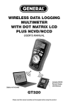
WIRELESS DATA LOGGING
MULTIMETER
WITH DUAL 7-SEGMENT LCD
PLUS NCVD/NCCD
USER’S MANUAL
(laptop not included)
GT310
(optional RD330
not included)
Please read this manual carefully and thoroughly before using this product.
TABLE OF CONTENTS
Introduction. . . . . . . . . . . . . . . . . . . . . . . . . . . . . . . . . . . . . . . . 3 – 4
Key Features & Specs . . . . . . . . . . . . . . . . . . . . . . . . . . . . . . . . . . . 5
What’s in the Box . . . . . . . . . . . . . . . . . . . . . . . . . . . . . . . . . . . . . . 6
Safety Instructions . . . . . . . . . . . . . . . . . . . . . . . . . . . . . . . . . . 6 – 8
Product Overview . . . . . . . . . . . . . . . . . . . . . . . . . . . . . . . . . . 8 – 11
Setup Instructions. . . . . . . . . . . . . . . . . . . . . . . . . . . . . . . . . . . . . 11
Install Battery . . . . . . . . . . . . . . . . . . . . . . . . . . . . . . . . . . . . 11
Insert Test Leads . . . . . . . . . . . . . . . . . . . . . . . . . . . . . . . . . . 11
Operating Instructions . . . . . . . . . . . . . . . . . . . . . . . . . . . . . 12 – 19
General Instructions . . . . . . . . . . . . . . . . . . . . . . . . . . . . . . . 12
Measuring DC or AC Voltage . . . . . . . . . . . . . . . . . . . . . 12 – 13
Measuring Resistance or Capacitance . . . . . . . . . . . . . . . . . 13
Checking the Integrity of a Diode or the . . . . . . . . . . . . . . . . 14
Continuity of a Circuit
Measuring DC or AC Current . . . . . . . . . . . . . . . . . . . . . 14 – 15
Non-Contact AC Voltage/Current Detection (NCVD/NCCD) . . . 15
Going Wireless. . . . . . . . . . . . . . . . . . . . . . . . . . . . . . . . 16 – 19
Transmitting Data to a PC . . . . . . . . . . . . . . . . . 16 – 18
Receiving and Displaying Data from a
Second GT310 or a GT320. . . . . . . . . . . . . . . . . 18 – 19
Specifications . . . . . . . . . . . . . . . . . . . . . . . . . . . . . . . . . . . . 19 – 22
Maintenance Tips . . . . . . . . . . . . . . . . . . . . . . . . . . . . . . . . . . . . . 22
Optional Accessories and Replacement Parts . . . . . . . . . . . . . . . 22
Warranty Information . . . . . . . . . . . . . . . . . . . . . . . . . . . . . . . . . . 23
Return for Repair Policy . . . . . . . . . . . . . . . . . . . . . . . . . . . . . . . . 23
2
INTRODUCTION
Thank you for purchasing General Tools & Instruments’ GT310
Wireless Data Logging Multimeter with Dual 7-Segment LCD plus
NCVD/NCCD. Please read this manual carefully and thoroughly before
using the instrument.
The GT310 can measure—with better than 1% accuracy, in most
cases—the six electrical parameters (DC voltage, AC voltage, DC
current, AC current, resistance and capacitance) that most
professional-grade multimeters measure. Like other multimeters, it
can also be used to verify the integrity of a diode and to check for
continuity within a circuit. However, the GT310 has two safety and
convenience features—NCVD/NCCD and wireless device-to-device
communication—that many comparably priced multimeters lack.
NCVD and NCCD—non-contact voltage and current detection—
empower the electrician in several valuable ways. For example, the
meter’s integrated NCVD sensor can quickly determine which wire in
a group is “live” without the user having to “tap” all the lines. It is so
sensitive it can pinpoint the location of a 30VAC line inside PVC conduit
behind a wooden wall. The NCCD sensor in the GT310 is equally
impressive. It can detect as little as 500 mA of current flowing behind
a concrete or plaster wall, under a floor, above a ceiling, in an
overhead line, or in a buried underground cable. The NCCD sensor can
also detect RF signals (such as from a walkie-talkie) and magnetic
fields.
Wireless communication offers an additional level of safety and
convenience. Being able to read the meter’s measurements from up to
33 ft. (10m) away (on a PC, on a second multimeter in the GT Series,
or on the optional RD330 Remote Display with Memory) lets the
electrician observe the effect of throwing a switch or changing a
setting on a piece of equipment without having to be near it. If a
system or piece of equipment operates at high voltages, remote
display makes troubleshooting it safer. If multiple changes to another
system or piece of equipment are needed to troubleshoot a problem,
remote display may save an electrician considerable time by allowing
him or her to immediately see the results of each step taken without
having to shuttle between two areas.
3
The GT310 can be part of three different kinds of wireless
communication schemes.
1. The meter includes a small USB receiver—called a dongle—that
enables any PC to display all the information shown on the unit’s
display. The “Going Wireless” section of this user’s manual provides
instructions for downloading the software needed to activate this
connection. The advantage of using a PC’s monitor to display the
meter’s measurements is readability: readings sent to the screen
of a laptop or desktop computer are several inches high—large
enough to be visible across a room.
2. With two GT310s or one GT310 and one GT320 (essentially, a
GT310 with a dual dot-matrix display instead of a dual 7-segment
display), each meter can be configured to display its own
measurements on its upper readout, and receive and display the
other meter’s measurements on its lower readout. Both models
include the wireless transceiver module needed to “share” readings
remotely—improving safety in the process—in this way.
3. For even greater remote display versatility, consider purchasing
General’s RD330 Remote Display with Memory as an optional
accessory. The standalone 4 in. x 4 in. unit, which uses the same
wireless transceiver module as the GT310 and GT320, can not only
display the readings of two multimeters simultaneously on its own
dual LCD with 0.67 in. (17mm) high digits; it can also memorize up
to 99 readings or pairs of readings. In addition to its memory, the
advantages of using the RD330 as a remote GT310 display are
compactness and portability.
Another key feature of the GT310 is its pair of double-insulated fused
test leads. Like NCVD/NCCD and wireless device-to-device
communication, the fuse in the red test lead offers the electrician
safety and convenience. It not only prevents excessive currents from
flowing through the meter, potentially injuring the user and damaging
the meter. In addition, the position of the fuse makes changing it fast
and easy. In many other multimeters, changing a blown fuse requires
the user to open up the instrument.
The red lead has a unique square plug. The meter’s use of a square (+)
jack prevents potentially damaging use of industry-standard round,
non-fused leads.
4
KEY FEATURES & SPECS
• 12 functions, 33 ranges
• Measures AC/DC voltage (up to 750VAC/1000VDC), AC/DC current
(up to 400mA), resistance (up to 40mΩ) and capacitance (up to
100 uF)
• Verifies integrity of diodes and checks circuits for continuity
• Includes double-insulated test leads; red lead has fast-acting
ceramic fuse rated at 500mA/500V and unique square plug.
Corresponding square jack on meter prevents potentially damaging
use of round, non-fused leads.
• Includes non-contact AC voltage and current detection (NCVD and
NCCD) sensors with beeper
• CAT III 1000V, CAT IV 500V certified
• Wirelessly interfaces to PC at 2.4 GHz from up to 33 ft. (10m) away
via included USB dongle
• Includes transceiver module for wirelessly interfacing to second
GT310 or GT320 (functionally identical model with dot-matrix
display) or optional RD330 Remote Display with Memory
• Choice of 10 channels for each wireless link
• Two-line, 3-3/4 digit (4000 count), 7-segment LCD with 0.67 in.
(17mm) high digits on upper readout
• Auto ranging or manual ranging
• Data hold and zero adjust buttons
• Fifteen-minute Auto Power Off function
• Low battery indicator
• Ergonomic design with rugged rubber housing
5
WHAT’S IN THE BOX
The GT310 comes in a black soft pouch inside a box. Also inside the
box are:
• A pair of fused test leads (General Part No. TL300)
• A USB dongle (General Part No. GTSF05) for wireless viewing of
the meter’s display on a PC. Software for enabling the dongle to
display the GT310’s readings on a PC is downloadable from the
GT310 page of General’s website.
• A “9V” battery
• This user’s manual
SAFETY INSTRUCTIONS
!WARNING
To avoid possible electric shock or personal injury, and to avoid
damaging the meter or the equipment under test:
• Do not use the meter in any way not detailed in this manual or the
meter's safety features may be compromised.
• Before using the meter, inspect the case. Do not use the meter if it is
damaged. Look for cracks or missing plastic. Pay particular attention
to the insulation around the connectors.
• !WARNING Inspect the test leads for damaged insulation or
exposed metal. Check the test leads for continuity. Replace damaged
test leads before using the meter.
• For safety reasons, you cannot switch to using unfused test leads to
make measurements. YOU MUST USE FUSED TEST LEADS fitted with
a fast blow fuse rated at 500mA/500V. Using unfused test leads also
voids the limited warranty.
• Verify the meter’s operation by measuring a known voltage. Do not
use the meter if it operates abnormally. Protection may be impaired.
When in doubt, have the meter serviced.
• !WARNING Do not apply more than the rated voltage, as marked on
the meter, between the terminals or between any terminal and
ground.
6
• !WARNING Do not measure voltages above 500V in CAT III
installations.
• !WARNING Do not measure voltage with the rotary dial pointing
to the resistance (ohms), current, capacitance or NCVD or NCCD
positions. Never measure current with the dial pointing to the
resistance (ohms), capacitance or NCVD or NCCD positions.
• Use caution when working with voltages above 42V ACrms, or
60V DC. These voltages pose a shock hazard.
• Use the proper terminals, function, and range for all measurements.
• !WARNING Do not operate the meter around explosive gas, vapor,
or dust.
• !WARNING When using the probes, keep your fingers behind the
finger guards. Do not touch the metal probes of the test leads when
making a measurement.
• When making connections, connect the black (–) test lead before
connecting the red (+) test lead; when disconnecting, disconnect the
red (+) test lead before disconnecting the black (–) test lead.
• Disconnect circuit power and discharge all high-voltage capacitors
before measuring/testing resistance, continuity, diodes, or
capacitance.
• For all DC functions in both auto ranging and manual ranging modes,
to avoid the risk of shock due to possible improper reading verify the
presence of any AC voltages by first using the AC voltage
measurement function. Then select a DC voltage range equal to or
greater than the AC range.
• Before measuring current, turn off power to the circuit before
connecting the meter.
• Do not operate the meter with the case (or part of the case)
removed.
• Replace the battery as soon as the low battery indicator “
”
appears. Operated with a weak battery, the meter might produce
false readings that could lead to electric shock and personal injury.
• Remove the test leads from the meter before opening the meter
case or battery compartment.
7
PRODUCT OVERVIEW
Fig. 1 shows the labels and positions of the controls, indicators and
connectors on the front and top of the GT310. Familiarize yourself with
their functions, as explained below, before moving on to the Setup
Instructions and Operating Instructions.
GT310
Fig. 1. The
GT310’s controls,
indicators and
connectors
1. Replaceable 2.4GHz transceiver module (on top of unit)
2. NCCD sensor (on top of unit)
3. NCVD sensor (on top of unit)
4. Two-line, 7-segment LCD
5. Flashing red/green indicator of operation in NCVD/NCCD mode
8
6. Two-function Range button:
a) In all measurement modes, press briefly to exit Auto ranging
mode (default) and enter Manual Ranging mode. With two
exceptions (the highest voltage ranges), each subsequent brief
press of the button decreases the measurement sensitivity
(increases the full-scale measurement range) by a factor of
10 (one decimal place)
b) In all measurement modes, press and hold for >3 seconds to
exit Manual Ranging mode and enable Auto ranging
7. Multi-function Power/Tx/Rx/Ax button:
appears at
a) Press briefly to enable transmission (Tx) mode;
upper right of display
b) Press briefly a second time to enable reception (Rx) mode;
appears at upper right
c) Press briefly a third time to enable transmission and
reception (Ax mode); both icons appear
d) Press briefly a fourth time to disable transmission and
reception (both icons disappear)
e) With rotary dial in any position but OFF, press and hold for
>3 seconds to power meter on or off.
8. Adj. Zero button (press briefly to reset readout)
9. Two-function Buzzer button:
a) Press briefly to turn backlight on/off
b) Press and hold for 3> seconds to turn beeper on/off
( appears/disappears at right of display)
10. Multi-function Select/0-9 button:
a) In voltage and current measurement modes, press briefly to
switch from DC measurement (default) to AC measurement
b) With rotary dial set to
position, press briefly to
switch from resistance measurement mode (the default) to
diode integrity check mode. Press briefly again to switch to
continuity check mode. Press briefly again to switch to
capacitance measurement mode. Press briefly again to return
to resistance measurement mode
9
c) In channel entry mode (with channel number flashing in top
or bottom readout), press briefly to increment channel
number. Pressing the button briefly with the display showing
CH-9 resets readout to CH-0
11. Two-function Hold/CH button:
a) Press briefly to hold (freeze) reading(s). Press briefly again to
release hold.
b) Press and hold for >3 seconds to enter Hi channel entry
mode. In Hi channel entry mode, press briefly to enter Lo
channel entry mode. In both modes, if no entry is made within 10
seconds, readout(s) revert to showing real-time measurements.
12. Rotary dial
13. COM jack for black (negative) test lead
14. Jack for red (positive) test lead
15. Battery compartment (on back of unit)
16. Black (negative) test lead
17. Red (positive) test lead. Contains fast-acting ceramic fuse rated
at 500mA/500V
18. Protective caps for test leads
The table below explains the symbols and abbreviations used on the
meter and in this manual.
Electrical Symbols Used On the Meter and In This Manual
Adjust reading to zero
Wireless transmit mode
Wireless receive mode
Alternating voltage / current
Direct voltage / current
Negative
Freeze / Hold reading
Wireless Transmit / Receive (Tx/Rx) channel 0-9
10
Diode
Auto ranging
Low battery
Overvoltage Category 3
Overvoltage Category 4
Ground
Beeper
Non-Contact Voltage (AC) Detection
Non-Contact Current (AC) Detection
SETUP INSTRUCTIONS
INSTALL BATTERY
The battery of your GT310 may or may not already be installed. If the
display remains dark after you turn the rotary dial to any position other
than OFF:
• Return the rotary dial to the OFF position.
• Disconnect test leads.
• Flip the meter over and lift the bottom of the yellow foldaway stand
on the back with your fingertip or a flat-blade screwdriver.
• Loosen and remove the two Phillips-head screws securing the
rectangular yellow plastic battery compartment cover. Set the cover
aside.
• Install a fresh “9V” battery in the compartment, with the (+) terminal
(anode) on the right (with the back of the meter facing you).
• Replace the battery compartment cover and resecure it with the
two screws.
INSERT TEST LEADS
Plug the red (fused) test lead into the right (red) socket on the front of
the meter and plug the black lead into the black socket. Remove the
clear plastic caps from the tips of the leads.
11
OPERATING INSTRUCTIONS
GENERAL INSTRUCTIONS
• To hold (freeze) a reading, briefly press the Hold/CH button.
• To turn the beeper on or off, press and hold the Buzzer button.
• To turn the backlight on or off, briefly press the Buzzer button.
• The meter is equipped with an Auto Power Off (APO) function that is
triggered by 15 minutes with no input. It cannot be disabled. To
“wake up” the meter in the same measurement state (but not
transmission/reception state) it was in when the APO function
activated, briefly press the Power/Tx/Rx/Ax button (Callout 7 of
Fig. 1). You need not turn the rotary dial to power the meter on again.
• Each time you finish using the meter, turn the rotary dial to the OFF
position.
• To ensure the accuracy of measurements, make sure that the points
touched by the test probes are free from dirt, oil, lacquer, and similar
substances.
• Until you configure the meter for wireless operation, only the upper
readout will display measurements. In
“normal” operating mode, the display will
look
like this:
MEASURING DC OR
AC VOLTAGE
F! Do not exceed maximum ratings. Do not contact circuits or
parts of circuits in which voltages with amplitudes greater than 25V
ACrms or 35VDC may be present.
Turn the rotary dial to the V position. The unit mV will appear at the
right of the display. The symbol
will appear at the top left of the
display, below the word AUTO, indicating that the meter is ready to
measure DC voltage in Auto ranging mode.
To measure AC voltage, briefly press the Select/0-9 button to change
the
symbol to ~.
12
Touch the test leads to two points in a circuit at different electric
potential. A minus sign (–) at the left of the reading indicates a
negative voltage.
To switch to Manual Ranging mode, press the Range button briefly
once to remove the AUTO indication from the top left of the display.
With two exceptions (the highest ranges), each subsequent brief press
of the button decreases the measurement sensitivity (increases the
full-scale measurement range) by a factor of 10 (one decimal place).
If the measured voltage is greater than the full-scale range, the
readout will be OL. To return to Auto ranging mode, press and hold
the Range button.
In AC or DC voltage measurement mode, the meter presents an input
impedance of >10MΩ to the circuit under test.
MEASURING RESISTANCE OR CAPACITANCE
Before measuring resistance or capacitance, be sure to remove power
from the circuit under test and to discharge any high-voltage
capacitors in it.
Turn the rotary dial to the Ω position. The unit MΩ will appear at the
right of the display. The word AUTO will appear at the top left,
indicating that the meter is in Autoranging mode.
To measure the resistance between two points of a circuit, touch the
test leads to those two points.
To measure the capacitance between two points of a circuit, press the
Select/0-9 button briefly three times to change the MΩ symbol to the
letter F. Then touch the test leads to the two points of interest.
To switch to Manual Ranging mode, press the Range button briefly
once to remove the AUTO indication from the top left of the display.
Each subsequent brief press of the button decreases the measurement
sensitivity (increases the full-scale measurement range) by a factor of
10 (one decimal place).
13
CHECKING THE INTEGRITY OF A DIODE
OR THE CONTINUITY OF A CIRCUIT
Before checking a diode or checking for continuity, be sure to remove
power from the circuit under test.
Turn the rotary dial to the Ω position. With the symbol MΩ at the right
of the display, briefly press the Select/0-9 button once to call up the
diode symbol
.
Connect the red test lead to the anode (positive terminal) of the diode
to be tested, and the black test lead to its cathode (negative terminal).
Read the forward bias voltage value on the display. A typical silicon
diode has a forward bias voltage between 0.7 and 0.99V. A typical
germanium diode has a forward bias voltage between 0.3 and 0.36V.
A 0V reading in both directions indicates a shorted diode. An OL
reading indicates an open diode. In either case, the diode is defective
and should be replaced. An OL reading also may indicate that the
polarity of the test leads is reversed. This test can be used to
distinguish the anode and cathode of a diode.
To enter Continuity Check mode, briefly press the Select/0-9 button
once with the diode symbol
showing on the display. This will
change the diode symbol to the Ω unit. If the icon is not visible at
the right of the display, activate the beeper by pressing the Buzzer
button.
In Continuity Check mode, the initial reading will be OL. Touch the test
leads to any two points in the circuit. If the resistance between the
points is <30 Ω, the meter will produce a long beep.
MEASURING DC OR AC CURRENT
F! The circuit to be tested may not carry a voltage in excess of
1000VDC or 750VAC. Applying a current of >500 mA will blow the fuse
in the red test lead. To remove the fuse, unscrew the top of the red
lead. Replace the blown fuse with a fast-acting ceramic fuse with a
rating of 500mA/500V.
Turn the rotary dial to the uA or mA position, depending on the
expected amplitude. The unit uA or mA will appear at the right of the
display. The word AUTO will appear at the top left, indicating that the
meter is in Auto ranging mode.
14
The default mode is DC current measurement (indicated by the
symbol near the top left of the display). To measure AC current, press
symbol to ~.
the Select/0-9 button to change the
Touch the test leads to two points in the circuit and read the displayed
value. A minus sign (-) at the left of the reading indicates a negative
value in DC current mode.
If applying current produces a reading of OL in uA Measurement
mode, switch to mA Measurement mode.
To switch to Manual Ranging mode, briefly press the Range button
once to remove the AUTO indication from the top left of the display.
Each subsequent press of the Range button decreases the
measurement sensitivity (increases the full-scale measurement range)
by a factor of 10 (one decimal place). If the measured current
amplitude is greater than the full-scale range, the display will show
OL. To return to Auto ranging mode, press and hold the Range button.
NON-CONTACT AC VOLTAGE/CURRENT DETECTION
(NCVD/NCCD)
Turn the rotary dial to the NCVD or NCCD position. Move the meter at
least several feet away from all wiring and briefly press the Adj. Zero
button. This maximizes the sensitivity of the NCVD or NCCD sensor.
Holding the meter in your hand, slowly move its top toward the known
or suspected source of voltage or current. As the meter approaches
the potential source of AC voltage or current, the display reading will
increase, the beeper will increase its speed, and a light (red for
voltage, green for current) behind the left side of display will flash
faster. The display reading is a relative value with no units. When the
reading peaks, briefly press the Hold button to freeze it.
To use the meter to distinguish a true “live” wire from a “ghost” live
wire, turn the rotary dial to the NCVD position, move the meter away
from all wiring, and press the Adj. Zero button. Plug the red test lead
into the red front-panel socket. Touch the tip of the lead to the
suspected live wire and note the display reading. Also touch other
suspected sources. The true live wire will produce the highest reading.
15
GOING WIRELESS
Transmitting Data to a PC
Use the following procedure to enable your GT310 to display its
readings on a PC monitor using digits that are several inches high—
large enough to be visible across a room.
You will first download and install the software that enables your
GT310 to communicate with the GTSF05 wireless USB receiver
(dongle) supplied with the meter. The final few steps of the procedure
explain how to match the software’s receiving channel to the
transmitting channel of the GT310.
1. Go to www.generaltools.com and enter GT310 in the SEARCH box.
2. On the GT310 page, click the “Download General Tools Product
Software” button.
3. Save <GTSF05_Setup.zip> to your desktop.
4. Click the Open button on the icon.
5. Highlight <GTSF05_Setup.msi>
6. Use a utility like WinRAR to extract <GTSF05_Setup.msi> to your
desktop.
7. Double-click <GTSF05_Setup.msi>; doing so opens a window titled
“Welcome to the DMMD_PCViewSetupWizard”. Click Next.
8. Click Next to install <DMMD_PCView> on your computer in a folder
named <C:\ProgramFiles(x86)\DMMD_PCView\>. To install the
program elsewhere, click Browse and choose an alternate location.
9. The next window confirms the installation. Click Next to continue.
10. The next window is titled <Installing DMMD_PCView>. Installation
typically takes less than 1 minute.
11. Click Close to exit.
12. Note that a GTSF05.exe icon has been added to your PC’s desktop
and Start button.
13. Double-click the icon to open the program.
14. A “Tips” window will appear asking you to “Please insert GTSF05
dongle!”
16
15. Plug the dongle into any open USB port on your computer. Doing so
will cause the following screen to appear.
16. On the meter, press the Power/Tx/Rx/Ax button once. The
icon will appear at right. You will next choose CH-1 as the meter’s
transmitting channel. To do so, press and hold the Hold/CH
button. When a flashing “0” (the default channel number) appears
at the right of CH- on the upper readout, quickly (within 10
seconds) press the Select/0-9 button once to advance the channel
counter to “1”. Quickly save the setting by pressing and holding
the Hold/CH button.
17. On the “DMMD_PCView GTSF05” screen, click the Scan CH
button. The program will begin scanning Channels 0 through 9.
Scanning will stop when the GT310’s transmission on Channel 1 is
detected, causing the � button to turn green.
18. Click again on the green � button to produce a display like the
following:
17
19. The reading on the DMMD_PCView screen will continue to
duplicate the contents of the GT310’s upper readout.
Receiving and Displaying Data from a Second GT310 or a GT320
To configure your GT310 to receive display measurements and
indications from another GT310 or a GT320 wireless multimeter, use
the Power/Tx/Rx/Ax button.
When the meter is powered on, the default setting is no
communication.
To enable transmission, briefly press the
Power/Tx/Rx/Ax button once. A
icon
will appear at the right of the upper readout
and the display will look like this:
To enable reception, briefly press the
Power/Tx/Rx/Ax button a second time.
The
icon will disappear and a
will appear at the right of
the lower readout. In “receive only” mode, your GT310 will not display
any of its own measurements on the upper readout; it will only display,
on its lower readout, measurements from a second wireless
multimeter.
Immediately after you enable receive mode,
your GT310 will operate in “standby receive
mode” until you synchronize its receiving
channel with the transmitting channel of the
other meter. Before you synchronize the two
meters, the display will look like this:
After you synchronize the two multimeters,
the new display will duplicate the data
shown on the second meter and look like
this:
To match the receiving channel of your GT310 to the transmitting
channel of the second multimeter, press and hold the Hold/CH
button, and then press it briefly to cause the lower readout to show
CH-0. Quickly (within 10 seconds), press the Select/0-9 button as
many times as needed until the channel number on the lower readout
matches the transmitting channel number of the second multimeter.
18
To enable transmission and reception,
briefly press the Power/Tx/Rx/Ax
button a third time. This will cause both
“satellite dish” icons to appear at the right
of the display. The upper readout will
display data from your GT310 and the
lower readout will display data from the
second multimeter. The composite display will look like this:
SPECIFICATIONS
GENERAL SPECIFICATIONS
• Maximum Voltage between Terminal and Ground: CAT III 1000V,
CAT IV 500V
• Test Leads Characteristics: Double sheath, soft PVC wire fitted with
500mA/500V fast-acting ceramic fuse measuring 6mm across
x 32mm long. Red lead also has unique square plug compatible with
(+) jack on meter.
• Display Type: Two-line, 3-3/4 digit (4000 count), 7-segment LCD
with 0.67 in. (17mm) high digits on the upper readout
• Sampling Rate: 3 times 1 sec.
• Maximum Voltage Measurement: DC 1kV , AC 750V
• Input Impedance in Voltage Measurement Mode: >10MΩ
• Maximum AC/DC Current Measurement: 400mA
• Maximum Resistance Measurement: 40MΩ
• Maximum Capacitance measurement: 100uF
• Diode Integrity Test Voltage: 1.5V
• Continuity Check Threshold: <30Ω with beeper
• Non-contact AC Voltage Detection Range: 50V to 1 kV or higher;
100 to 250V in “Live or Ghost” mode
• Non-contact AC Current Detection Range: 100mA to 1000A or higher
• Transmission/Reception: Half-duplex; Ten channels centered on
2.4GHz
19
• Communication Range: >33 ft. (10m)
• Auto Power Off Interval: 15 minutes
• Backlight Fadeout Interval: 90 seconds
• Power Source: (1) “9V” battery
• Power Consumption: <3mA (standby mode);
<20mA (normal operating mode); <25mA (transmitting mode);
<60mA (receiving mode); <80mA (transmit + receive mode)
• Dimensions (Excluding Test Leads):
7.1 x 3.7 x 2.1 in. (180 x 95 x 54mm)
• Weight (Excluding Battery): 1 lb. (450g)
MEASUREMENT RANGES,
RESOLUTIONS & ACCURACIES
AC Voltage (Manual Range)
Range
0-400mV
0-4V
0-40V
0-400V
0-750V
Resolution
0.1mV
0.001V
0.01V
0.1V
1V
Accuracy
±0.6% of reading ±3 digits
±0.6% of reading ±3 digits
±0.6% of reading ±3 digits
±0.6% of reading ±3 digits
±1.0% of reading ±5 digits
DC Voltage (Manual Range)
Range
0-400mV
0-4V
0-40V
Resolution
0.1mV
0.001V
0.01V
Accuracy
±0.6% of reading ±2 digits
±0.6% of reading ±2 digits
±0.6% of reading ±2 digits
0-400V
0-1000V
0.1V
1V
±0.6% of reading ±2 digits
±0.8% of reading ±2 digits
AC Current (uA Setting, Manual Range)
Range
0-400uA
0-4mA
20
Resolution
0.1uA
1uA
Accuracy
±0.15% of reading ±5 digits
±0.15% of reading ±5 digits
DC Current (uA Setting, Manual Range)
Range
0-400uA
0-4000uA
Resolution
0.1uA
1uA
Accuracy
±0.12% of reading ±3 digits
±0.12% of reading ±3 digits
AC Current (mA Setting, Manual Range
Range
0-40mA
0-400mA
Resolution
0.01mA
0.1mA
Accuracy
±0.15% of reading ±5 digits
±0.15% of reading ±5 digits
DC Current (mA Setting, Manual Range)
Range
0-40mA
0-400mA
Resolution
0.01mA
0.1mA
Accuracy
±0.15% of reading ±5 digits
±0.15% of reading ±5 digits
Resistance (Manual Range)
Range
0-400Ω
Resolution
0.1Ω
Accuracy
±0.7% of reading ±5 digits
0-4kΩ
0-40kΩ
0-400kΩ
0-4MΩ
0-40MΩ
0.001kΩ
0.01kΩ
0.1kΩ
0.001MΩ
0.01MΩ
±0.6% of reading ±2 digits
±0.6% of reading ±2 digits
±0.7% of reading ±2 digits
±1.5% of reading ±5 digits
±2.0% of reading ±6 digits
Capacitance (Manual Range)
Range
0-52nF
0-520nF
0-5.2uF
0-52uF
0-100uF
Resolution
0.01nF
0.1nF
0.001uF
0.1uF
0.1uF
Accuracy
±3% of reading ±7 digits
±3% of reading ±5 digits
±3% of reading ±5 digits
±10% of reading ±10 digits
±10% of reading ±10 digits
Diode Integrity Check
Range
1.5V Open
Resolution
0.001V
Accuracy
±10% of reading ±5 digits
21
Continuity Check
Range
400Ω (Display reading)
Beeper sounds when<30Ω
Resolution
0.0Ω
0.0Ω
Accuracy
±0.8% of reading ±6 digits
±0.8% of reading ±6 digits
Non-Contact AC Voltage Detection
Range
0000 (signal strength)
Buzzer speeds up and red backlight flashes
when signal strength >0010
Resolution
1 count
1 count
Non-Contact AC Current Detection
Range
0000 (signal strength)
Buzzer speeds up and green backlight flashes
when signal strength >0010
Resolution
1 count
1 count
MAINTENANCE TIPS
The GT310 is not waterproof or water-resistant; avoid water, toxic
environments and temperature extremes.
Do not turn on the meter immediately after it has been taken from a
cold to a warm environment. The condensation that may result could
destroy the unit. Leave the meter switched off and wait until it reaches
room temperature.
Remove the battery when you do not expect to use the unit for a long
period of time (several months).
Clean the display by wiping it with a damp soft cloth. Never use
solvents or abrasives.
OPTIONAL ACCESSORIES AND
REPLACEMENT PARTS
• Replacement GTSF05 Wireless USB Receiver (dongle)
• Optional RD330 Remote Display with Memory
• Replacement TL300 Fused Test Leads
22
WARRANTY INFORMATION
General Tools & Instruments’ (General’s) GT310 Wireless Data Logging
Multimeter with Dual 7-Segment LCD plus NCVD/NCCD is warranted to
the original purchaser to be free from defects in material and
workmanship for a period of one year. Subject to certain restrictions,
General will repair or replace this product if, after examination, the
company determines it to be defective in material or workmanship.
This warranty does not apply to damages that General determines to
be from an attempted repair by non-authorized personnel or misuse,
alterations, normal wear and tear, or accidental damage. The defective
unit must be returned to General Tools & Instruments or to a Generalauthorized service center, freight prepaid and insured.
Acceptance of the exclusive repair and replacement remedies
described herein is a condition of the contract for purchase of this
product. In no event shall General be liable for any incidental, special,
consequential or punitive damages, or for any cost, attorneys’ fees,
expenses, or losses alleged to be a consequence of any damage due
to failure of, or defect in any product including, but not limited to, any
claims for loss of profits.
RETURN FOR REPAIR POLICY
Every effort has been made to provide you with a reliable product of
superior quality. However, in the event your instrument requires repair,
please contact our Customer Service to obtain an RGA (Return Goods
Authorization) number before forwarding the unit via prepaid freight to
the attention of our Service Center at this address:
General Tools & Instruments
80 White Street
New York, NY 10013
212-431-6100
23
GENERAL TOOLS & INSTRUMENTS
80 White Street
New York, NY 10013-3567
PHONE (212) 431-6100
FAX (212) 431-6499
TOLL FREE (800) 697-8665
e-mail: [email protected]
www.generaltools.com
GT310 User’s Manual
Specifications subject to change without notice
©2012 GENERAL TOOLS & INSTRUMENTS
NOTICE - WE ARE NOT RESPONSIBLE FOR TYPOGRAPHICAL ERRORS.
MAN#GT310 7/12/12