1
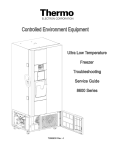
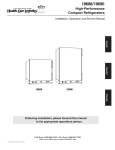
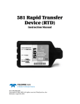
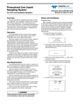
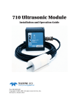
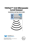
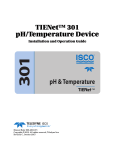
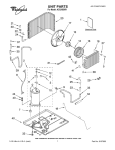
5800 Temperature Sensor
Cable Assembly
Instruction Sheet #60-4702-070
Revision D, January 14, 2013
Removal and Replacement
Overview
Required Parts and Tools
The 5800 has two refrigeration temperature sensors,
one attached to the evaporator coil to measure the
evaporator temperature, and the other mounted on the
refrigerator’s rear wall to measure the refrigeration air
temperature. The two refrigeration temperature sensors
are part of the temperature sensor cable assembly kit.
Note that this instruction sheet is for both the 5800
sampler and the older model 4700 sampler. Some information applies solely to the 4700 sampler, and will be
clearly marked as such.
Before attempting to remove and replace a module,
observe the following precautions:
Replacement cable assembly kit 69-5804-054
#2 Phillips screwdriver
#3 Phillips screwdriver
Wire cutters
●
●
●
●
15
/16" open wrench
Clear silicone sealant
Cable tie 489-0110-00 (for best results, soak in
water for one hour prior to use)
●
●
●
Removal
1. Unplug the line cord to remove AC power.
2. Remove the cover brace, back cover, and insulation panel (Figure 1).
WARNING
Removing a module exposes you to electrical and
mechanical hazards. Always disconnect the AC
power cord before attempting to remove any
module. Only trained service personnel may
remove or replace these modules.
Refrigeration
module
Insulation
panel
CAUTION
Removing the sealed modules will expose the internal
components. Wet or corrosive atmospheres may attack
the exposed refrigerator components. Always service
modules in a dry, corrosion-free environment.
Back
Cover
Cover
brace
CAUTION
Modules contain circuit boards and sensitive electronics
that can be damaged by a discharge of static electricity.
Avoid touching the internal components. Only handle
the module by the edges or exterior surfaces.
Figure 1: Remove back cover and insulation
CAUTION
3. Cut the cable tie from the power cord that runs
through the refrigeration assembly (Figure 2).
Electrical connectors and wires can be damaged if
improperly handled. Electrical connectors must only be
handled by the connector body. Never grasp the wires
or use tools to disconnect a connector. Never allow a
module to hang by its wiring.
Cut cable tie
CAUTION
Earth ground bonding conductor. Do not
remove or disconnect. If this conductor must
be disconnected to remove a module, it must
be reconnected when installing the
replacement module.
Figure 2: Cut cable tie from line cord (Full line cord
length not depicted)
1
Instruction Sheet #60-4702-070 Revision D, January 14, 2013
4. Remove the refrigeration module mounting
screws (Figure 3).
Note that the refrigeration module has an adhesive strip just above the rear coils. The bottom
center screw may be slightly hidden by this
strip.
5. Carefully pull the module out and rotate clockwise to expose the wiring connectors.
b. Slide the bushing sideways away from the
refrigeration module until it is free (Figure 5).
Use care to avoid bending the refrigeration
tubing.
CAUTION
Keep the module as close to the refrigerator body as
possible to avoid pulling the wiring taut and damaging
the connectors.
Figure 5: Remove power cord
c. Pull the power cord through the refrigeration
module.
Turn module out
and left
7. Open the flip cover of the sampler and remove
the control panel mounting screws.
Adhesive
strip
Figure 3: Remove the refrigeration module mounting screws
Figure 6: Control panel module removal
6. Remove the power cord, following substeps a, b,
and c.
a. 230 VAC Models Only – Remove the AC Plug
adapter from the end of the power cord by
first cutting away the plastic heat shrink tubing. Then pull the adapter off, leaving just the
North American 115 VAC plug (Figure 4).
8. Lift the control panel to expose the wiring connectors, taking care not to put strain on the
wires.
Removing the Cable Assembly
1. Disconnect the temperature sensor cable from
connector P3 (P5 for older model 4700 samplers) on the control board and set the control
panel back in place.
CAUTION
When disconnecting a cable connector, always grasp the
connector itself and not the wires.
CAUTION
Figure 4: Remove adapter from power cord
(230 VAC models Only)
When connecting the temperature sensor cable to P3 on the
control board, ensure that it is not reversed. The slots on the
cable connector must be facing inward.
2
Instruction Sheet #60-4702-070 Revision D, January 14, 2013
2. Remove the large ferrite bead from the connector end of the cable (it snaps apart). Retain the
ferrite bead for installation on the replacement
cable assembly.
Ferrite Bead
Cable
Connector
Figure 7: Ferrite bead on cable connector end
(May not be present on older 4700s)
3. The evaporator sensor is mounted on the sixth
coil up on the evaporator (see Figure 8). Note
that some older 4700s have a metal sensor, while
current models have a black rubber molded
housing. Cut the ties holding the evaporator sensor in place and move it out of the frame.
Close-up of
sensor in
holder
Figure 9: Removing rear wall sensor
(power supply plate not shown)
5. The wiring assembly enters the rear of the refrigeration cabinet just above the upper left corner
of the fan (Figure 10).
Unscrew the black cord-grip fitting from the
bulkhead fitting in the refrigerator’s rear wall.
Cord-grip
fitting
Older (4700 only)
Bulkhead
fitting
Current (4700 & 5800)
Figure 8: Removing evaporator temp sensor
Cut cable ties
Temperature
sensor cable
4. Slide the rear wall sensor out of its plastic holder
(located behind the power supply plate, Figure 9
below).
Figure 10: Temperature sensor wiring entry at rear
of cabinet
3
Instruction Sheet #60-4702-070 Revision D, January 14, 2013
10. Gently press the metal sensor into the plastic
holder behind the power supply plate until it
snaps into place.
11. Replace the refrigeration module, insulation,
rear panel, and cover brace.
6. Gently loosen the bulkhead fitting with the 15/16"
open-end wrench and unscrew it from the refrigerator cabinet. Pull the cable connector out
through the threaded opening.
Temp sensor
cable connector
Cord grip
fitting
Note
5800 rear wall
When reinstalling all self-tapping screws, avoid destroying
the plastic threads. First, seat each screw in its hole and,
without pressing down, rotate the screw counter-clockwise
until it falls into its thread groove with a "click." Then tighten
the screw.
Bulkhead
fitting
Figure 11: Temperature sensor cable and bulkhead
connector
12. Ensure that the control wiring runs through the
notches in the plastic refrigerator body.
The refrigeration module and rear compartment
of the cabinet have adhesive strips and Permagum2 (caulking cord sealant) protecting the components (Figures 12 and 13). Ensure that all
Installing the New Cable Assembly
1. Carefully feed the connector end of the new
cable through the threaded opening from the
rear of the cabinet.
2. Apply a coating of the clear silicone sealant
(such as Dow Corning®1 737 RTV) to the threads
of the cable’s bulkhead fitting.
3. Screw the bulkhead fitting into the cabinet wall
until the threads bottom out. Smooth the excess
silicon sealant around its base to seal the joint.
4. Tighten the black plastic cord-grip fitting over
the bulkhead fitting.
5. Clean the control panel’s mounting surface on
the face of the refrigerated compartment. This
will help ensure that the gasket will seal the
enclosure.
adhesive strips and Permagum are still in place
before reassembly.
CAUTION
The adhesive strips and Permagum are required to prevent air
flow between the condenser coil and the evaporator plate.
Without this protection, water condensation on the coil will
cause ice build-up, resulting in poor refrigerator performance.
Note
Two thick, black cables connect the power supply with
the module and compressor (see Figure 12). Ensure
that these cables are side by side and not
crossed during reassembly.
6. Install the ferrite bead 3/4" from the cable connector. Wrap the cable one complete turn
around the bead and snap it closed (Figure 7).
7. Attach the new cable to P3 on the control board
(or P5 for older 4700s).
8. Align the control panel over the mounting holes
and secure it with the mounting screws. Torque
screws 1.8 to 2.0 Nm (16 to 18 in/lbs).
9. Using the two plastic cable ties, mount the black
sensor on the sixth coil of the evaporator as
shown in Figure 8.
To operate correctly the sensor must be
mounted in the exact position shown.
Permagum
sealant
Power supply
cables
Note
Adhesive strips
Figure 12: Rear view with module removed
(Adhesive strips, Permagum sealant, and power cables)
When installing the black
molded sensor, be careful not to
overtighten the cable tie on the
sensor body, as internal
damage could occur. The sensor
should be snug against the coil,
but the rubber housing should not be visibly dented.
1. Dow Corning® is a registered trademark of Dow Corning Corporation.
2. Permagum is a registered trademark of the Presstite Engineering
Company.
4
Instruction Sheet #60-4702-070 Revision D, January 14, 2013
Adhesive
strip
Center
screw
Permagum
sealant
Figure 13: Rear view of refrigeration module
(Adhesive strip and Permagum sealant)
13. Hold the line cord taut to remove any slack, and
attach a cable tie 489-0110-00 (Figure 14).
CAUTION
When installing/replacing the refrigeration unit, the line
cord MUST be properly secured. This is to ensure that
the cord cannot be pushed into the enclosure and catch
in the fan.
Cable Tie
Bushing
Figure 14: Secure AC Power Cord (Full length of line
cord not depicted)
14. Restore AC power. After 30 minutes, perform the
refrigerator temperature diagnostic test (see
your user manual). As the refrigerator cycles off
and on, the reported temperature will rise above
and below the set temperature. However, the
average reported value should be the same as
the set temperature.
Teledyne Isco
P.O. Box 82531, Lincoln, Nebraska, 68501 USA
Toll-free: (866) 298-6174 • Phone: (402) 464-0231 • Fax: (402) 465-3001
E-mail: [email protected]
Teledyne Isco is continually improving its products and reserves the right to change product
specifications, replacement parts, schematics, and instructions without notice.