1
BSc FINAL PROJECT
Submitted for the
BSc Honours in Computer Science
May 2009
Liquid Brain Music: Phase II
by
Nathan Vincent Woods
Contents
Acknowledgments ................................................................................................................................ 1
Abstract ................................................................................................................................................ 2
1
2
Introduction .................................................................................................................................. 3
1.1
Project Brief .......................................................................................................................... 3
1.2
Aims and Objectives .............................................................................................................. 3
1.3
Report Structure ................................................................................................................... 4
Background Survey ....................................................................................................................... 5
2.1
Artificial Life .......................................................................................................................... 5
2.1.1
2.2
4
Pattern Matching .................................................................................................................. 7
2.2.1
Run Length and Block Size ............................................................................................. 7
2.2.2
Binary String Comparison .............................................................................................. 8
2.2.3
Data Normalisation ..................................................................................................... 10
2.3
3
Cellular Automata ......................................................................................................... 5
Computer Music .................................................................................................................. 11
2.3.1
Digital Audio ................................................................................................................ 11
2.3.2
Sound Synthesis .......................................................................................................... 13
2.3.3
Broader Musical Context ............................................................................................. 18
Project Management .................................................................................................................. 19
3.1
Planning .............................................................................................................................. 19
3.2
Management ....................................................................................................................... 19
3.2.1
Backups ....................................................................................................................... 19
3.2.2
Supervision .................................................................................................................. 20
3.2.3
Coding practices .......................................................................................................... 20
Project Requirements, Analysis and Specification ...................................................................... 21
4.1
Requirements ...................................................................................................................... 21
4.2
Project Analysis ................................................................................................................... 22
4.2.1
Additive Synthesis Engine............................................................................................ 23
4.2.2
Incorporation .............................................................................................................. 23
4.2.3
Pattern Matching ........................................................................................................ 24
4.2.4
Ethical Considerations ................................................................................................. 25
4.2.5
Implementation .......................................................................................................... 26
4.3
Project Goals and Objectives............................................................................................... 26
4.4
Deliverables ........................................................................................................................ 27
4.5
5
Software Development ............................................................................................................... 29
5.1
Specification ................................................................................................................ 29
5.1.2
Analysis ....................................................................................................................... 29
5.1.3
Design and Implementation ........................................................................................ 30
System Integration .............................................................................................................. 35
5.2.1
Specification ................................................................................................................ 35
5.2.2
Analysis ....................................................................................................................... 35
5.2.3
Design and Implementation ........................................................................................ 36
5.3
7
Additive Synthesis Engine ................................................................................................... 29
5.1.1
5.2
6
Specification ........................................................................................................................ 27
Pattern Matching ................................................................................................................ 38
5.3.1
Specification ................................................................................................................ 38
5.3.2
Analysis ....................................................................................................................... 39
5.3.3
Design and Implementation ........................................................................................ 39
Testing and Experimentation ...................................................................................................... 42
6.1
Unit Testing ......................................................................................................................... 42
6.2
User Interface Testing ......................................................................................................... 42
6.3
Requirements Testing ......................................................................................................... 43
6.4
Experimentation ................................................................................................................. 43
6.4.1
Sample Rate ................................................................................................................ 43
6.4.2
Bit Resolution .............................................................................................................. 43
6.4.3
Number of Partial Harmonics ...................................................................................... 43
6.4.4
Number of Amplitude Envelopes ................................................................................ 44
6.4.5
Maximum Number of Voices ....................................................................................... 44
6.4.6
Parameter Ranges ....................................................................................................... 44
Critical Evaluation ....................................................................................................................... 45
7.1
Research.............................................................................................................................. 45
7.2
Project Planning .................................................................................................................. 45
7.2.1
8
Task Management ....................................................................................................... 45
7.3
Software Development ....................................................................................................... 47
7.4
Testing................................................................................................................................. 47
7.5
Evaluation of Aims and Objectives ...................................................................................... 48
7.6
Reflection ............................................................................................................................ 49
Conclusion................................................................................................................................... 50
9
8.1
Future Work ........................................................................................................................ 50
8.2
Conclusion........................................................................................................................... 50
Bibliography ................................................................................................................................ 52
Appendix A.
Initial Project Brief ....................................................................................................... 54
Appendix B.
Initial Task List with Milestones and Deliverables ....................................................... 55
Appendix C.
Risk Analysis ................................................................................................................ 57
Appendix D.
Project Time Plans ....................................................................................................... 59
Appendix E.
Tick() and Start() Methods from AddSynth Class ......................................................... 62
Appendix F.
PatternClassify() Method from PatternMatcher class ................................................. 64
Appendix G.
Sample of Black-box UI Testing ................................................................................... 65
Appendix H.
User Guide................................................................................................................... 67
Acknowledgments
I would like to give special thanks to following people who have made the completion of this project
possible:
My parents, for their continued support and generous funding.
Luke and Phoebe, for also being immediate family members, and therefore almost automatically
worthy of a mention.
Dr. Darryl N. Davis, for proposing the topic and giving me the opportunity to undertake this project,
as well as for his support and guidance.
Christopher Turner, who, though I have never met, made this project possible through his excellent
work on the original Liquid Brain Music system.
Roy Herrod, for his unyielding knowledge on anything computer or math related and his willingness
to always help.
Dave and Sher Bremmer for all the support, the food and the shelter.
Finally and most importantly, my girlfriend, Kristin, for putting up with all my nonsense and for her
much appreciated editorial input.
1
Abstract
This document is a final report designed to accompany the research and implementation of a project
named Liquid Brain Music: Phase II. The project explores the concept of using artificial life systems
to control the generation and synthesis of audio. This report will document the stages of research
and development undertaken throughout the duration of the project.
Cellular automata will be considered as the artificial life system in this project, based on Stephen
Wolfram’s concept of elementary cellular automata, and will use, and continue to develop upon, the
work of Christopher Turner, who designed and built the original Liquid Brain Music system.
Sounds are produced by using additive synthesis methods implemented using C++, OpenAL and the
Synthesis Toolkit. By using pattern matching rules to classify output from the cellular automata and
then using this data to parameterise the additive synthesiser, the two aspects of the system are
connected into a complete software application.
2
1 Introduction
This project, Liquid Brain Music: Phase II, examines the concept of using artificial life systems to
control the generation and synthesis of audio to the extent that it might be considered music. This
project is a continuation of work already done in this area by Christopher Turner (Turner, 2008) and
hopes to expand upon the work already completed.
This report will give an overview of the research undertaken for the project, as well as detailing the
design and implementation. I will also be evaluating this project to assess its success.
1.1 Project Brief
After discussion with my project supervisor the original brief for the project became:
Title: Liquid Brain Music: Phase II
Suits: GD, CS, SE, BIC
SYS: Prolog or C++/C#
Keys: Music, Games, AI, A-Life
Ratings: Research: 4, Analysis: 3, Design: 3, Implementation Volume: 3, Implementation Intensity: 3
Outline:
This project will examine the possibility of controlling the generation and synthesis of music using an
artificial life system. Work on this project will be a continuation of work already undergone in this
area, with the hopes of extending the original system to offer a wider range of sounds, and more
control over the sounds, through the creation of an additive synthesis engine. The software will be
developed into what could be considered a compositional tool or an instrument, rather than just a
game.
The original brief for the project can be found in Appendix A.
As well as slightly altering the project’s initial specification the title has been changed from Liquid
Brain Music to Liquid Brain Music: Phase II, to indicate the fact that it is a continuation of the
previous work.
1.2 Aims and Objectives
Based on the updated project brief it is possible to identify the main aims for the project. Firstly, an
additive synthesis engine needs to be created, that is compatible with the pre-existing audio output
engine. This can be broken down into the following objectives:
Research audio synthesis techniques, in particular additive synthesis.
3
Familiarise myself with the pre-existing software, specifically the audio output engine.
Design and build a compatible additive synthesis engine
The next aim is to incorporate the additive synthesis engine into the original Liquid Brain Music
system, so that the audio can be controlled by its artificial life system. This can also be split up into a
number of objectives:
Familiarise myself with the original Liquid Brain Music system.
Incorporate the additive synthesis engine into the system.
Control the parameters of the additive synthesis engine using the artificial life system.
The final aim of the project is to update the original system to make it more compatible with the
additive synthesis engine and to allow the user more control over the parameters of the additive
synthesis engine. This will require satisfying the following objectives:
Update the user interface to better display the additive synthesiser’s parameters.
Increase the number of pattern matching rules used by the artificial life system.
Give the user manual control over parameters.
1.3 Report Structure
This report is split into a number of chapters, covering the stages of the project. Following this
introductory chapter, the report contains these sections:
Background Survey – an overview of the research undertaken in areas relevant to the
project.
Project Management – the considerations taken into planning and managing the project.
Requirements, Analysis and Specification – a more in-depth look at the requirements of the
project as well as analysis of the problem, leading to a more robust specification.
Software Development – documentation of the design and implementation of the software.
Testing and Experimentation – Examining the criteria by which the software can be tested
and looking at how experimentation has been used to refine the software.
Critical Evaluation – a personal evaluation of the success of all areas of the project.
Conclusion – closing thoughts about the overall success of the project and considerations of
any future work that might be undertaken.
4
2 Background Survey
2.1 Artificial Life
“Artificial life, or a-life, is devoted to the creation and study of lifelike organisms and systems built by
humans” (Levy, 1992)
Artificial life systems attempt to recreate these naturally occurring systems and organisms, and, in
difference to the traditional methods of studying biology by observation, they attempt to “put
together systems that behave like living organisms” (Langston, 2008). In this way, it is possible to
study the logic behind the way these systems evolve and develop an understanding of how complex
living systems work.
Cellular Automata and Neural Networks are common methods of implementing artificial life, though
in this system, only cellular automata will be considered.
2.1.1
Cellular Automata
Cellular automata is a subset of artificial life systems. Simple cellular automata, like the one used in
the original Liquid Brain Music system, are made up of a 2-dimensional grid of cells, each of which
may be in one of two states; on or off.
As the cellular automata updates in discrete time steps, or generations, each cell’s state depends on
the state of those cells surrounding it, known as the cell’s neighbourhood.
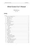
A commonly used neighbourhood is the Moore neighbourhood (Tyler, 2005), where a cell’s
neighbourhood comprises of the 8 cells immediately surrounding it, as shown in Fig. 1. Rules can
thus be created depending on how many of the cell’s neighbours are on or off in that generation.
The Moore Neighbourhood is used in one of the most well known cellular automata known as
Conway’s Game of Life. The Game of Life is a zero-player game, so after an initial set of states for
the cell’s has been determined, their evolution over time is controlled by just four simple rules:
An on cell with fewer than 2 on neighbours becomes off
An on cell with more than 3 on neighbours becomes off
An on cell with 2 or 3 on neighbours remains on
An off cell with exactly 3 on neighbours becomes on
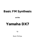
These rules are able to generate extremely complex patterns that are capable of running for
thousands of generations. Fig. 2 shows a simple example of the Moore neighbourhood being used in
Conway’s Game of Life.
5
Figure 1.
The Moore Neighbourhood (left). The Wolfram Neighbourhood (right). The grey cells
represent the neighbourhood of the black cell.
The original system uses Elementary Cellular Automata and can be considered a 1-dimensional array
of cells. “The cellular automata consists of a line of cells, each colored black or white. At every time
step there is a definite rule that determines the color of a given cell from the color of that cell and its
immediate left and right neighbors of the step before.” (Wolfram, 2002, p24). The neighbourhood
for a cell when using elementary cellular automata is comprised of the cell in its position in the
previous generation, as well as the cells to the left and right of that, as shown in Fig. 1.
Figure 2.
Four generations of Conway’s Game of Life.
The method used in the system provides a large number of different rules which can be use to
determine the state of the cells in the next generation. If the 3 cells in the neighbourhood are
treated as a 3-bit binary integer (000 – 111) then there are 8 different combinations for the 3 cells.
In order to decide whether the value of the neighbourhood should cause the current cell to be on or
off in this generation, the value can be mapped to an 8-bit binary value. This 8-bit binary value
determines the rule that is being used and, as 8-bits can represent 256 (0-255) decimal integer
values, there are said to be 256 distinct rules. For instance, 01011010, or 90 in decimal, would be
known as Rule 90. Each bit is numbered from 0 – 7 (from right to left), and depending on the value
of the neighbourhood, the corresponding digit from the 8-bit rule is used. If this bit is a 0, the cell
will be off in this generation, if it is a 1 the cell will be on in this generation.
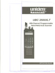
For example, if the neighbourhood of a cell was 101 (5 in decimal), and we were using rule 90
(01011010), the fifth digit of the rule would be used, in this case 0, so the cell would be off in this
generation. An example of rule 90 being used can be seen in Fig. 3.
6
Figure 3.
An elementary cellular automata after 8 generations using rule 90.
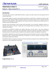
As well as using this elementary approach to determine the state of cells, a totalistic approach can
be used. Rather than treating the 3 cells as a binary value, the bits are simply added together. For
example the neighbourhood 101 would therefore be 1 + 0 + 1 = 2. The same rule mappings can be
used here, but they are effectively limited as the values generated will be between 0 and 3, rather
than 0 and 7. Fig. 4 demonstrates the difference between using elementary and totalistic methods.
Figure 4. An example of how elementary and totalistic methods of determining a cell’s state
differ. Both neighbourhoods are identical and use Rule 74 to determine the cell’s state.
2.2 Pattern Matching
Pattern matching involves checking a data set to see if patterns, or elements of a pattern, are
present. In pattern matching, the pattern to be searched must be strictly defined before searching.
2.2.1
Run Length and Block Size
In the original Liquid Brain Music system pattern matching was used to check for patterns in
sequences of black and white cells. This involved looking for a sequence of 1 to 4 consecutive black
or white cells, and two different approaches were used to measure these sequences, thereby giving
16 different pattern matching rules. The two approaches used were Run Length and Block Size.
7
Run Length works by looking for a series of like-coloured cells in a sequence, without paying
attention to the cells surrounding it. For example, if looking for runs of 3 white cells in a sequence of
6 white cells, the result would be 2, as the sequence contains 2 sets of 3 white cells. This can be
seen in Fig. 5
Block Size differs in that it takes into account the adjacent cells. If the previous example was used
and blocks of 3 white cells were searched for in a sequence of 6 white cells the result would be 0.
The size of the block would be 6 white cells and not 3. Only a block of exactly 3 white cells would
give a result. This can also be seen in Fig. 5.
Figure 5.
2.2.2
An example of the pattern matching rules Run Length and Block Size showing the
number of positive results on identical 16-bit binary sequences.
Binary String Comparison
Rather than taking the same approach to the previous pattern matching rules, by interrogating a
single binary sequence, instead the concept of comparing two binary strings will be considered. As
the cellular automata updates, the current 1-dimensional array of cells, which can be treated as a
binary string, can be compared with the previous 1-dimensional array of cells. A number of methods
for comparing two binary strings have been considered.
2.2.2.1
Hamming Distance
One of the simplest methods of comparing two binary strings is by finding the Hamming distance
between them. “The distance between two binary patterns in terms of the number of elements in
which they differ, is called the Hamming distance” (Aleksander and Morton, 1995, p7). As an
example, if you had two 16-bit binary strings, 1011010010011010 and 1010110010110110 (see Fig.
6), you are able to observe that these strings differ in the 4 th, 5th, 11th, 13th and 14th bits, there are
therefore 5 elements in which the strings differ, so the Hamming distance is said to be 5. Hamming
distance essentially shows how many bits would need to be altered in order to make the strings the
same.
8
Figure 6.
2.2.2.2
Two 16-bit binary strings being compared to find the Hamming distance. A black cell
indicates a 1 and a white cell indicates a 0.
Jaccard Similarity and Difference
Another method which has been considered is Jaccard Similarity, or Coefficient, and Jaccard
Difference.
“Jaccard's coefficient (measure[s] similarity) and Jaccard's distance (measure[s]
dissimilarity) are measurement[s] of asymmetric information on binary (and non-binary) variables.”
(Tenkomo, 2006). When dealing with binary strings, the Jaccard Similarity can be found by dividing
the number of elements that are positive in both strings by that same value plus the number of
elements that are positive in the first string, but negative in the second, plus the number of
elements that are negative in the first string, but positive in the second string. This can be
represented as p/p+q+r, where p is the number of elements positive for both, q is the number of
elements positive in the first but not the second, and r is the number of elements positive in the
second but not the first. Jaccard difference can then be found by taking the similarity away from 1.
Fig. 7 shows an example, using the same 16-bit binary sequence used for Hamming distance, of how
to find Jaccard Similarity and Difference.
Figure 7.
Two 16-bit binary strings compared to find the Jaccard Similarity and Jaccard
Difference.
9
2.2.2.3
Dice’s Coefficient
The last binary string comparison method that has been considered is Dice’s Coefficient. Dice’s
Coefficient is similar to Jaccard Similarity but “gives twice the weight to agreements” (Hillenmeyer,
2006). When dealing with binary string comparison, Dice’s coefficient can be found using the
equation 2p/2p+q+r. Fig. 8 shows a worked example of finding Dice’s Coefficient using the same 16bit binary strings as the previous examples.
Figure 8.
2.2.3
Two 16-bit binary strings compared to find Dice’s Coefficient.
Data Normalisation
In the original Liquid Brain Music system, in order to use the information from the pattern matcher
to control the parameters of the synthesiser it was necessary for the results to be in the range 0 – 1.
Any additional pattern matching rules implemented will also need to return a value between 0 and
1.
Fortunately, Jaccard Similarity, Jaccard Difference and Dice’s Coefficient are already in that range
when they are calculated, which only leaves Hamming distance as a concern.
The simplest way in which the Hamming distance can normalised is to divide the number of
elements that differ by the total number of elements in a string. This is essentially the same as using
a linear transformation in the form new = (original – minimum) / (maximum – minimum). In the case
of Hamming distance, the minimum will always be 0 – this is the case if the two strings match exactly
– and the maximum will always be equal to the length of the string – the case if the strings are
different for every single element.
10
The linear transformation will always be new = (original – 0) / (maximum – 0) or new =
original/maximum.
2.3 Computer Music
2.3.1
Digital Audio
A sound is caused by a displacement of air, which causes vibrations. The properties of these
vibrations, or sound waves, affect the sound, particularly the frequency, which alters the perceived
pitch of a sound, and the intensity, which alters the perceived volume of the sound to the listener.
In humans, these vibrations are interpreted by the auditory system, where they are converted to
nerve impulses sent to the brain, which enables the perception of sound.
Naturally produced sounds are continuous and therefore discretisation is necessary before audio can
be handled digitally by a computer. In order to do this, a sound wave must be sampled at regular
intervals, and data of the amplitude at that point in the wave recorded, an example can be seen in
Fig. 9. This method of taking regular samples, which together form a digital representation of the
original analogue signal, is known as Pulse-code Modulation or (PCM).
Figure 9.
A sine wave (red) sampled at regular intervals, with arbitrary bit-resolution, provides
a sampled wave (blue). The x-axis shows time and the y-axis shows amplitude.
The quality of digital audio is directly related to the rate at which these samples are taken, known as
the sampling rate, as a higher sampling rate allows the original sound to be recreated with greater
accuracy. The bit resolution also determines the quality of the audio. The bit resolution is the range
of values that the amplitude can take, for instance with a bit-resolution of 2-bits, there are only 4
different values that the amplitude can take (see Fig. 10), with a bit resolution of 16-bits, there are
65,536 different values the amplitude can take. The standard for CD quality audio is to take a
sample 44,100 times every second (44.1Khz) with a 16-bit resolution per sample.
11
Figure 10. A sine wave (red) sampled with a bit resolution of 2-bits, providing only 4 values for
amplitude. The samples are shown by the blue line.
2.3.1.1
Nyquist Theorem
When trying to reproduce audio digitally, the sample rate can have other implications than just
affecting the quality of the audio.
If for instance, you took a sine wave, oscillating at 440Hz, and sampled it at the same frequency,
there would be no sound. Each time a sample is taken would be as the wave reaches zero, as shown
in Fig. 11.
Figure 11. A sine wave (red) sampled at a rate equal to its frequency. The blue crosses indicate
the points at which the wave is sampled.
If a wave is sampled at too low a frequency, then the wave may not be reproduced accurately.
Commonly, this may result in a different frequency being sampled, which can be seen in Fig. 12.
12
Figure 12. A sine wave (blue) sampled at a rate less than twice its frequency. The resulting
wave (red) oscillates at a lower frequency than the original wave.
The Nyquist Theorem states that “For lossless digitization, the sampling rate should be at least twice
the maximum frequency responses.” (Marshall, 2001). By applying this theory, a sound wave can be
recreated in digital form with all the information of the original audio.
The resolution and sampling rate will need to be considered carefully during implementation. A high
bit resolution and sample rate would be ideal, but there will be a trade-off between this and the
level of performance.
2.3.2
Sound Synthesis
“Sound synthesis is the process of producing sounds. It can re-use existing sounds by processing
them, or it can generate sounds electronically or mechanically” (Martin, 1996, p2)
While it would be possible to use existing sound samples as the basis of the synthesis and
manipulating them to create new sounds, this project intends to focus on the concept of generating
new sounds from scratch.
2.3.2.1
Subtractive Synthesis
Subtractive synthesis is a popular and simple method of synthesising sounds. With it, “you start with
a waveform and then filter out harmonics or bands of harmonics to produce a range of different
sounds and tonal colours.” (Computer Music, 2005)
The timbre, or tonal quality, of a sound is the result of its harmonic content. A sound is made up of a
fundamental frequency and then a number of harmonics at decreasing levels of amplitude. A
harmonic is an integer multiple of the fundamental frequency.
For instance a square wave (see Fig. 13), which produces a hollow sound, contains only odd
numbered harmonics, and a sawtooth wave (see Fig. 14), which has a bright sound, contains odd
and even numbered harmonics
13
Square Wave
1.20
Relative Level
1.00
0.80
0.60
0.40
0.20
0.00
1
2
3
4
5
6
7
8
9
10
Harm onic Num ber
Figure 13. Harmonic content of a square wave
Saw tooth Wave
1.20
Relative Level
1.00
0.80
0.60
0.40
0.20
0.00
1
2
3
4
5
6
7
8
9
10
Harm onic Num ber
Figure 14. Harmonic content of a sawtooth wave
Filters can be applied to a subtractive synthesiser, filtering out certain frequencies and altering the
timbre of the sound.
2.3.2.2
Additive Synthesis
“While subtractive synthesis is sometimes likened to sculpting… parallels can be drawn between
additive synthesis and painting, where the artist starts with a blank canvas and adds paint to build
up a picture” (Computer Music, 2005)
Additive synthesis is a complex form of sound synthesis with greater scope for producing different
sounds. It’s based on the work of Joseph Fourier, which states that “periodic waveforms can be
deconstructed into combinations of simple sin waves” (Greenspun and Roads, 1996, p1075).
The sine wave has no harmonic content, it’s simply the fundamental frequency, and by adding sine
waves we could simulate other sounds. For instance, in figure 13, if we were to use sine waves at
14
the frequencies and relative levels represented in the chart, it would create a waveform resembling
a square wave. A simplified version, created using 6 sine waves can be seen in Fig. 15 and 16.
Figure 15. Six sine waves that could be combined to create an additive square wave
Figure 16. The resultant additive square wave made from combining 6 sine waves
With additive synthesis, it’s also possible to simulate real instruments or other real-world sounds. It
also allows for greater control over the harmonics in the sound. All the harmonics could be treated
separately with regards to how they evolve over time, by applying separate amplitude and
modulation envelopes to each harmonic, though this could increase complexity very quickly and
usually harmonics would be grouped into a few bands.
Due to the complexity of additive synthesis some experimentation will need to be done to make
sure that performance is reasonable. A major consideration will be the number of harmonic partials
in a voice.
15
2.3.2.3
Other Synthesis Techniques
There are a great deal more techniques that can be used to alter a sound which are not reliant on
the type of synthesis being used. A number of these techniques will be considered.
2.3.2.3.1
Amplitude Envelopes
An attack, decay, sustain, release (ADSR) envelope, is a popular amplitude envelope. It is used to
control the way the amplitude of a sound evolves over time. The attack section relates to the period
of time it takes for an audio signal to go from zero to its peak. The attack section is usually triggered
by a key on message. Decay is the amount of time it takes for the signal to fall from its peak to a
sustain level. Sustain describes a level which is the maximum amplitude for the signal. Release
describes the amount of time it takes for the signal to decrease from its sustain level back to zero.
This is usually triggered by a key off command.
The sections of an ADSR envelope can be seen in Fig. 17. The way an ADSR envelope affects a sound
wave can be seen in Fig. 18.
Figure 17. An attack, decay, sustain, release envelope (ADSR). The coloured sections indicate
the different parts of the envelope.
Figure 18. An ADSR envelope (red) applied to a simple sine wave. The resulting audio signal is
shown in blue.
16
2.3.2.3.2
Low Frequency Oscillators
Another commonly used method to change the sound a synthesiser produces over time is to employ
a low frequency oscillator or LFO. In original analogue synthesisers LFOs were used to “produce low
frequency control voltages” (Russ, 1996, p93), and these can be recreated easily in digital
synthesisers.
An LFO will usually oscillate at a frequency below the range of human hearing, typically between 1hz
and 50hz. This low frequency wave can then be used to modify an audio signal. This is most usually
used to alter the frequency of an audio signal over time, causing the pitch to alter over time, and can
be achieved by adding the LFO signal and audio signal together.
In order to vary the amount of effect an LFO has on an audio signal, a value called LFO rate is used.
This is a value which can be used to scale the LFO, either increasing it or decreasing it, and will either
minimise or maximise the affect on the audio signal. Fig. 19 shows an audio signal oscillating at
440Hz being changed over time by an LFO sine wave at 20Hz, with an LFO rate of 3.
Figure 19. An audio signal (blue) at 440Hz, being altered by an LFO sine wave (red) at 20Hz
multiplied by an LFO rate of 3 (green) produces a new audio signal (burgundy)
2.3.2.3.3
Phase
As additive synthesis makes use of several sine waves added together, it is possible to move some of
the sine waves out of phase with the rest. By doing this, it is possible to drastically alter the shape of
the signal produced. For instance, in Fig. 20, the third harmonic has been shifted in phase, altering
the wave produced.
17
Figure 20. The blue line shows an additive square wave made from 6 harmonic partials. The
red line shows the same wave, but with the third harmonic shifted in phase.
2.3.3
Broader Musical Context
The sounds that are currently generated by the system may be difficult to define as music, especially
if you do not consider the wider context , as they may not contain many of the structures that would
be associated with the musical form. They could be considered as ‘Sound Art’ (Sexton, 2007, p85),
especially considering the visual aspect of the system that accompanies and influences the sounds.
The work of Brian Eno is relevant as he coined the phrase ‘Generative Music’ (Eno, 1996) to help
describe works of his, such as Discreet Music (1975). Generative Music refers to any musical sounds
that are produced within a set of defined parameters, but without the intervention of a human.
The work of composer John Cage has also been influential in pushing the boundaries of what is
accepted as music. One of Cage’s aims was “Giving up control so that sounds can be sounds”
(Nicholls, 2007, p2)
18
3 Project Management
3.1 Planning
Due to the size and nature of this software development task, it was of great importance to plan for
the project before design and implementation began. An agile development method was used. Due
to my inexperience in the audio programming and the practical aspects of sound synthesis a
development model that allowed for inspection and adaptation to the plan meant that any
unforeseen problems could be addressed as they occurred or that new features or ideas could be
added later if required.
In order to be able to better manage the project, a set of tasks and deliverables were identified.
Tasks could then be given an initial estimated duration, as well as proposed start and end dates. The
project was specifically split into staged deliverables so that there were more frequent deliveries of
useful software and also as a safeguard against any serious problems affecting the project’s ability to
be finished. A set of milestones were also identified from the tasks and deliverables. The initial set
of tasks, milestones and deliverables can be found in Appendix B.
Early on in the planning stage a risk analysis was undertaken to assess all the possible threats facing
the project. These risks were given a severity and likelihood value which allowed a quantifiable risk
value to be determined. This information was then taken into account when planning the project.
Documentation of the risk analysis can be found in Appendix C.
Time plans, in the form of GANNT charts, were used throughout the project to make scheduling
easier, and to help visualise when tasks, milestones and deliverables were due. Due to the agile
development method, the time plan was revisited several times throughout the project. The first
time plan proved too optimistic to keep to and as a result the project fell behind. Another time plan
was created to address this, and a third was used once a more definite list of tasks that could be
achieved in the remaining time was finalised. These time plans can be found in Appendix D.
3.2 Management
3.2.1
Backups
An important part of a software project such as this is maintaining a backup system, not only to
protect against hardware failure or loss of work, but also to keep multiple versions of the source
code, should a roll-back to a previous version be required. For this reason a well structured file
system was used to save multiple versions of the source code, as well as notes, diagrams, reports,
etc. Fig. 21 shows an example of how a file structure was used.
19
Figure 21. Example of the file system and version control technique used during the project.
Backups were also made on separate, external hard drives to ensure their availability should the
main development computer become compromised.
3.2.2
Supervision
In order to keep the project on track, weekly meetings were held with the project supervisor. This
allowed a constant review of the project’s progress to ensure it was not falling significantly behind.
Supervisor meetings were also an opportunity to discuss how aspects of the project could be
tackled.
3.2.3
Coding practices
To make working with the source code as easy as possible coding standards were maintained. This
was of particular importance as the software development involved working with someone else’s
code. Annotations were made to add clarity to the code and consistent standards for naming
variables, functions and classes were used. Variable names used the camelCase convention, and
underscores at the start of variables were used to indicate they were members of a class. Variable,
function and class names were also considered carefully to make sure they were logical and
meaningful.
20
4 Project Requirements, Analysis and Specification
4.1 Requirements
As stated in the previous section, the software development would be broken down into three
distinct phases. Firstly, an additive synthesiser would be created. Secondly, this new synthesis
engine would be incorporated into the original Liquid Brain Music system. Finally, new pattern
matching rules would be built into the system to expand upon those already in place. To better
understand what was required from each of these phases, a set of requirements was determined.
Having predetermined requirements also allowed for requirements testing at the end of software
development, to ensure that targets were met and the software did what it was intended to do.
The additive synthesis engine requires:
Create a synthesis engine capable of outputting audio using the pre-existing audio engine
from Liquid Brain Music.
Ensure that the additive synthesis engine uses enough partial harmonics to give a reasonable
quality and diversity of sounds, but not so many that it has a severe negative effect on
performance.
Allow a reasonable number of these synthesis engines to play back audio simultaneously.
Ensure that the sample rate is set to a level that gives a reasonable quality of audio playback,
without hampering the quality or number of voices.
Ensure that the frequency of the harmonic partials does not exceed half the value of the
sample rate.
Ensure that the bit-resolution of the sampled sound waves is at a reasonable level to allow
good quality audio without wasting memory or effecting playback.
To use a reasonable number of amplitude envelopes to control different parts of the sound
without effecting the quality of playback.
As well as these requirements, the additive synthesiser requires a number of parameters which will
control the way the resulting audio will sound, as shown in Table 1.
21
Parameter Name
Frequency
Panning
LFO State
LFO Rate
LFO Freq
Partial state (for all partial harmonics)
Partial level (for all partial harmonics)
Partial phase (for all partial harmonics)
Attack (for all amp. Envelopes)
Decay (for all amp. Envelopes)
Sustain (for all amp. Envelopes)
Release (for all amp. Envelopes)
Gain
ADSR Mode
Values
Somewhere in the range approx. 20Hz - 25KHz
Left to Right ((-1) - 1)
On/Off
0 - 100
Approx. 0 - 50Hz
On/Off
Volume Level
Angle
Time Duration
Time Duration
Volume Level
Time Duration
Volume Level
On/Off
Table 1. Required parameters for additive synthesis engine
Incorporating the additive synthesis engine into the Liquid Brain Music system requires:
Display all the parameters and information about the new additive synthesiser on screen
Allow multiple instances of the additive synthesiser, and the ability to view parameters and
information for all instances.
Use the CA and pattern matching rules to control the parameters of the new additive
synthesiser.
Save and Load data from the new additive synthesis engine within the system.
Allow the additive synthesis engine to be muted to cease audio playback.
The requirements for expanding the pattern matching system are as follows:
Use binary string comparison techniques to create new pattern matching rules using the
data generated by the CA.
Incorporate the new pattern matching rules into the user interface, allowing them to be
selected by the user.
Include the ability to override pattern matching, so that manual control can be used instead.
Allow the user to manually control the value (within its specified range) of parameters
where the pattern matching rules have been overridden.
4.2 Project Analysis
To be able to meet these requirements it was important to analyse them, taking into account the
information learnt from background research.
22
4.2.1
Additive Synthesis Engine
In order to begin working on the additive synthesis engine it is important to understand how
communication between the additive synthesis engine and pre-existing audio output engine would
work. The original audio engine contained two buffers of 4096 x 2 (8192), experimentation had
already been done to determine that this was a reasonable number and size for the buffers, without
causing serious audio lag or stutters. The audio engine sits in a continuous loop where it requests
data, in PCM format, until a buffer is full. At this point the buffer is streamed to an audio hardware
device where it is output as sound. To be able to work with the audio output engine, it is necessary
to have a function that provides PCM data to fill the buffers.
Providing PCM data to the audio engine in the correct format requires deciding upon the sample
rate and the bit-resolution of the samples being taken, which will require some experimentation
during development to determine.
As using additive synthesis requires the management of a lot more sound waves than in the
subtractive synthesis engine of the original Liquid Brain Music system, some experimentation will
also be required to determine how many partial harmonics can be used per voice, and how many
voices can be used. The original system had one wave per voice for the audio signal, plus an
additional three waves that were used to modulate the signal, requiring just four waves per voice.
With a total of 8 voices, this meant the system would be handling 32 waves at most. In the additive
synthesis engine each voice will be made up from a number of sine waves. Assuming 8 sine waves
are used per voice, plus another sine wave for modulation, this would mean 9 waves per voice and
72 waves to have 8 simultaneous voices.
Another requirement of the additive synthesiser is to use a number of amplitude envelopes to
control the way the sound changes over time. The original system used just one, but as the sounds
from the additive synthesiser are made from a number of separate waves it is possible to have
several amplitude envelopes. It may be necessary to group the harmonic partials so that similar
partials are controlled by the same amplitude envelope. A logical way to do this would be to group
odd and even partials or high and low partials, or a combination of both.
As the additive synthesiser will have a lot more going on, in terms of pure number crunching, than
the original system it will be of great importance to experiment to find optimal levels for the sample
rate, bit-resolution, number of waves per voice, number of amplitude envelopes per voice and
number of voices, to ensure a good quality of audio playback.
4.2.2
Incorporation
Once an additive synthesis engine capable of working with the pre-existing audio engine has been
created, incorporating it into the Liquid Brain Music system should be fairly straightforward. The
23
complications involve using the results of the current pattern matcher to parameterise the
synthesiser and updating the UI to incorporate the new parameters.
The system currently works by creating an array of voices, which each contain a subtractive
synthesis engine, so in theory, it should be simple enough to replace these with additive synthesis
engines if they have been designed to be compatible. This will also allow multiple voices, which can
easily be adjusted for experimentation purposes.
The pattern matcher in the original system produces a value between 0 and 1, regardless of which
rule is being used. In order to determine a value for a specific parameter, a minimum and maximum
value need to be given. The actual value of the parameter can then be found by multiplying the
pattern matcher’s value by the maximum value minus the minimum value, and then adding on the
minimum value to offset. For instance, if we had a frequency parameter with minimum 50 and
maximum 10,000, and the pattern matcher gave a value of 0.5, to find the actual value for frequency
would be (0.5 * (10,000 – 50)) + 50 = 5,025. All the parameters that are included in the system will
therefore need to have an associated minimum and maximum value.
In order to display the parameter correctly, each parameter also needs to have a name string
associated with it, and a description string to give information about the parameter to the user.
Displaying all the new parameters on screen may also present a challenge. The original system had
only 13 parameters that needed to be displayed on screen. The proposed parameters for the
additive synthesiser consist of 7 base parameters, plus 3 parameters for every harmonic partial, plus
4 parameters for every amplitude envelope.
Assuming 8 harmonic partials and 4 amplitude
envelopes per voice, this would mean 47 parameters that somehow need to be displayed, which will
almost certainly mean some adjustments to the user interface are required.
Because the parameters of the additive synthesiser are so different to those previously used in
Liquid Brain Music, the existing saving and loading mechanics will no longer work. They will at least
need to be disabled to stop errors occurring in the software, but ideally they will be updated to allow
the new set of parameters to be saved out and loaded in to the system.
4.2.3
Pattern Matching
The pattern matching aspect of the new system will involve working with the cellular automata in
the original Liquid Brain Music system. As already detailed, the new pattern matching measures will
involve comparing one or more binary sequences, in the form of the CA’s 1-dimensional array of on
and off cells, rather than just looking at a single binary string. This will mean that previous
generations of the CA output will need to be stored, so that the current generation’s output can be
compared to it.
24
In order to maintain consistency with the original pattern matching rules, each new pattern added
will need to be given a unique consecutive ID number, and also a string for its name. This should
allow them to be integrated more easily into the system, and allow them to be displayed and
selected by the user in much the same way as the original rules.
Some consideration will need to be given to the efficiency of the pattern matching operations.
Currently, the system checks to see if any parameters are using a rule, and only checks and updates
a rule if it is being used. This will optimise performance if only a small number of the rules are being
used, but if all 16 rules are in use it will mean that the same binary sequence is checked 16 times. As
the binary string comparison techniques which are going to be used are all based on the number of
similarities and differences between two strings, it would be possible to compare the strings and
update a number of rules all with a single pass through the two strings.
To remain compatible with the mechanics of pattern matching and its effects on parameter values,
the values determined by the pattern matching rules must be in the range 0 – 1. As discussed in the
background section, the binary string comparison techniques being used should all produce values in
this range anyway, so this should not cause a problem.
In order to be able to override a pattern matching rule and allow the user to manually adjust the
value of a parameter will require a slightly different approach. As discussed above, the pattern
matcher generates a value between 0 and 1, and the value of a parameter is determined according
to this value and its own minimum and maximum values. In order to manually override pattern
matching, this process will have to be ignored. Rather than generating a value between 0 and 1 and
scaling the parameter’s value accordingly, adjustments will need to take place directly a parameter’s
value. Checks will need to be made to ensure that values cannot be manually adjusted outside a
parameter’s minimum and maximum values, and a step size will also need to be determined to
specify how much a parameter should be adjusted by. This will vary depending on the parameter
being adjusted, for instance, frequency, with values between 50Hz and 10,000Hz would require a
much larger step size than panning, with values between -1 and 1.
4.2.4
Ethical Considerations
There are very few serious ethical considerations affecting this project. All audio aspects of the
system are generated from scratch by the software. It might therefore be debateable who is
responsible for any ‘music’ produced by the software, though this is not a major consideration at this
point.
Other than a project supervisor, no other people have been involved in the progression of this
project or the development of the software. While the project is based on the work of a previous
student, every effort has been made to acknowledge this and give credit where it is due.
25
4.2.5
Implementation
In order to be able to develop the software for this project, it was essential first to decide what
languages and APIs would be suitable for development.
It is worth noting that as this is a
continuation of previous work, which would be building on top of existing source code, a major
factor into the decisions on which languages and APIs to use was maintaining compatibility with the
original system.
The core programming language for the original Liquid Brain Music system was C++. This was a
sensible choice given the programs performance-oriented nature. C# might have been a potential
option, and may have been a more reliable and easy language to work with, due to managed code,
though this would also make it slower in performance than C++.
The graphics programming in the original was done using C++ and OpenGL. OpenGL was chosen
over DirectX and WinAPI because of its suitability to 2D graphics and because of its portability to
other systems. While there were no intentions of altering the way the CA displays during the
project, it was always possible that some alterations would need to be made, especially if
performance became an issue, which would require working with OpenGL. Changes to some aspects
of the user interface are required to update the software, particularly to display new parameters, so
simple adjustments using the current graphics API, OpenGL, seems like a logical choice.
The audio engine in the original system was created using OpenAL, an open source audio
programming library that’s modelled around OpenGL’s syntax. As the audio engine has already been
created, no extra work is required. However, if changes are necessary, OpenAL would have to be
used.
The original subtractive synthesis engine was created using the Synthesis Toolkit (STK), an open
source API, which contains a collection of classes written in C++. Like OpenGL, it’s portability to
other systems makes it a good choice. It’s designed specifically for creating audio synthesis and
audio processing software and is well suited to this task. As the original synthesis engine was
created using STK, using it in this project to build the additive synthesiser should ensure
compatibility with the existing audio engine.
There are possible alternatives for the audio programming, such as FMOD and Csound, but to
maintain compatibility with the original system, these were not considered.
4.3 Project Goals and Objectives
While a formal set of aims and objectives for the project was given in the introductory chapter, the
goals and objectives expressed here intend to give a more general idea of what is hoped this project
will achieve.
26
To expand upon the original system by offering a wider range of sounds through the
creation of an additive synthesiser.
To increase the number and type of pattern matching rules to give the user more choice for
controlling the audio.
To give the user more control over the sounds the system generates, so that the system may
be considered, in some sense, a compositional tool or virtual instrument.
To ensure that the system is relevant to, and can be used by, anybody; from complete
novices to music professionals
To provide a user interface that neatly displays all the available options and provides useful
feedback, both audibly and visually.
4.4 Deliverables
The project will involve the submission of a number of deliverables along the way, which will provide
evidence of progress.
Some of the required deliverables have already been achieved:
Initial Report
Interim Report
Stand-alone Additive Synthesis Engine
In addition to these completed deliverables, the following deliverables still remain:
Finished Liquid Brain Music: Phase II Software
Software documentation, user manual, etc
Final Report
Presentation.
4.5 Specification
Using C++ and Synthesis Toolkit build an additive synthesis engine
o
The additive synthesis engine must be compatible with the existing audio output
engine.
o
It must also be capable of outputting reasonable quality audio in real-time.
o
The additive synthesis engine must have an appropriate number of harmonic
partials and amplitude envelopes to offer a suitably wide variety of sounds, while
also maintaining a reasonable quality of playback.
27
o
The additive synthesis engine must include, at least, the parameters specified in the
requirements.
Using C++, OpenGL and STK, incorporate the additive synthesis engine into the original
Liquid Brain Music system
o
Display all parameter information onscreen to the user in a logical, uncluttered
manner.
o
Update the User Interface to reflect the changes to the system.
Allow the user to select to use multiple simultaneous additive synthesis voices.
Determine a reasonable maximum number of voices to allow for no
disruption to audio playback.
o
Use the CA and pattern matching rules provided by the original system to control
the parameters of the additive synthesiser.
o
Allow the user to mute some or all of the voices that are currently playing back.
o
Allow the user to save out and load in data from the additive synthesiser(s).
Using C++ add new pattern matching rules based on binary string comparison.
o
Generate rules to find:
Hamming Distance
Jaccard Similarity
Jaccard Difference
Dice’s Coefficient
o
Ensure that values determined by rules are in the range 0 – 1.
o
Incorporate the new pattern matching rules into the user interface so they can be
selected and used to control parameters.
o
Provide the option to override pattern matching rules, letting the user manually set
values for parameters.
Parameter values must be contained to a specific range.
Parameters must be adjusted in sensibly sized steps.
28
5 Software Development
As previously discussed, it was decided that the software development for this project would be split
into three phases. This approach was decided upon to ensure that each component of the software
worked in its own right before moving on to the next. This was particularly important as the later
phases were dependent upon the previous stages. For example, it would be necessary to have a
working additive synthesis engine before incorporating it into the Liquid Brain Music system.
For each phase of development, some analysis and design was taken into account before coding
began. Analysis and design worked as a good starting point, highlighting particular issues that
needed to be considered.
After analysis and design, coding began, which allowed for some
prototyping and re-evaluation of design. This proved to be very useful in determining what was
possible given the available technology and my previous inexperience in this area.
5.1 Additive Synthesis Engine
5.1.1
Specification
A full and detailed specification for the additive synthesis engine can be found in chapter 4.5. The
core requirement for the additive synthesis engine was to provide meaningful data for the existing
audio output engine, which in turn would output the data as audio. This required making sure that
the additive synthesis engine was compatible with the audio output engine.
5.1.2
Analysis
The most crucial part of the analysis for the additive synthesis engine was to examine the original
source code in Liquid Brain Music. This would help get an understanding of how to work with the
existing audio engine and ensure audio was output correctly.
It was decided at this stage, no alterations would be made to the existing code, unless it was
deemed absolutely necessary. Instead additional code would be added in a modular fashion, so that
it had as little impact on the working of the original code as possible. In this way it would be possible
to assume that the existing audio engine worked as it should and that any problems were as the
result of the new code I had implemented. This would allow my code to be updated, debugged or
removed entirely in isolation from the existing code.
In order to maintain consistency with the existing code, and to ensure compatibility, a similar
approach would be taken; a separate class would be written with the purpose of handling the job of
generating the required data to be supplied to the audio output engine. This also ensured that my
code would be compartmentalised from the original code.
29
It is also worth noting that the original code contained an abstract class, SignalGenerator, which
provided certain requirements of any class which would supply data to the audio output engine.
5.1.3
Design and Implementation
In order to be able to create an additive synthesis engine, it required that a number of sine waves be
produced and added together. The audio engine requires a series of PCM format data values at
regular time intervals, which essentially represent a discrete audio signal. The adding together of
sine waves allows this audio signal to be modelled and passed to the audio engine.
The first challenge of how to go about creating an additive synthesis engine was how I was going to
handle generating and maintaining a number of sine waves that would be required to produce the
tones. Fortunately, STK provided a class that can generate and manage a sine wave. This was used
due to its operational efficiency as well as the fact that it would make dealing with a large number of
sine waves relatively simple.
It was decided that a class named AddSynth would be created for handling everything to do with
generating the data to be supplied to the audio engine. However, each instance of Addsynth
required the use of several sine waves to generate an additive wave. As discussed in the background
section, additive synthesis works by adding together a number of simple sine waves to create a new
wave. For each time step, the output of the AddSynth would be the sum of a number of harmonic
partials, or sine waves. Fig. 22 shows an example of how this would work.
30
Figure 22. A diagrammatic view of how the AddSynth class might work. On the left, a collection
of sine waves, with frequency at multiples of the initial frequency. Top right, the AddSynth
Class, responsible for summing and processing the sine waves, then provides data to be
output by the Audio Engine (Bottom right).
One option was to create an array within AddSynth which would contain a number of these sine
wave classes. It was decided that this approach would not be suitable, however, as each sine wave,
or partial harmonic, would require other information, beside just the wave itself. In order to vary
the overall sound, each partial would at least need to have the ability to be on or off, and have its
own relative amplitude and frequency.
It was decided for this reason that a new class would be implemented to contain a sine wave and all
the associated data required for a partial harmonic. The class was named Partial, as, although
current plans only required the implementation of sounds using partial harmonics, this leaves the
31
option open to later implement partial inharmonics, that is, sounds made up of frequencies that are
not harmonic to one another. AddSynth could therefore contain a number of these Partial classes,
which could be used to find the appropriate data to pass to the audio output engine at every time
step.
In order to find the correct PCM value at every time step, it was necessary to have a Tick() function
in the AddSynth class, which was responsible for adding together the value from each partial it
contained. In order to get values from the Partial classes, they also contained a function called Tick()
which returned the current PCM value of its wave, adjusted by its relative level value. Whether or
not the partial was on or off also made a difference, as if the partial was off, a value of zero could be
returned.
The main issue with this approach is that when a sine wave is checked to provide a value for that
current time step, it returns a real number value between 0 and 1. In order to set an appropriate
level of quantisation for the audio, this needed to be converted into an integer value, within a
certain limit. For this reason, a maximum amplitude level was also provided for partials, which they
were scaled by to produce PCM data.
However, this causes another problem in and of itself: When all these scaled values are added
together in the AddSynth class, there is a good chance that their total will exceed the maximum
value for quantisation. For example, if you had a maximum amplitude of 100, and 4 partials with
relative amplitude levels of 1, 0.8, 0.6 and 0.4, if all their peaks coincided they would return values of
100, 80, 60 and 40 respectively. Adding these together would give a value of 280, which exceeds the
maximum value of 100, and would therefore be truncated to 100.
In order to prevent this
happening, the AddSynth class scales the total value by keeping a running total of all the relative
levels of the partials, and dividing the total by this. So in the previous example, 280 would be
divided by (1 + 0.8 + 0.6 + 0.4) = 2.8, which would give a value of 100, inside the range for maximum
amplitude.
In order to make the additive synthesis work correctly, it was also essential to make sure that each
partial was set to the correct frequency. As discussed earlier, partial harmonics are integer multiples
of the base frequency, and by varying the status (on/off) of a partial, or varying its relative level,
different tones are generated. Two methods were implemented in the AddSynth class called
Initialise() and Start(). There were two corresponding methods in the Partial class also. The two
methods were very similar except that Initialise() was used only at the start of the program to set
initial values, and Start() was used during the programs execution to deal with the base frequency
being changed. Both of these methods worked by checking through all the Partials in AddSynth, if
the first partial was found, the frequency and relative level for it were set. For each other partial,
32
the frequency for that partial was calculated, by multiplying the base frequency by the partial
number. This value was then checked to see if it was less than half the sample rate. Bearing in mind
Nyquist’s Theorem, discussed earlier, any waves with a frequency greater than half of the sample
rate would not be sampled frequently enough and would cause abnormalities during playback. If
the frequencies were below this value, the frequency and relative level for that partial could be set.
If they were above this value, the partial was given a default frequency of 0, so that it would not
have an effect on the resulting additive wave. It would have also been possible to set the partial’s
frequency, regardless of its value, and then check it during the Tick() function, not adding it in if its
value was too high. This approach would be less efficient, however, as it would require checking
every time Tick() was called (once every cycle), whereas to check it in Start() would require that the
operation only take place every time the frequency was altered.
The key difference between the Initialise() and Start() functions is that, when they are initialised, all
partials have their status set to on, whereas, when Start() is used, the status is not altered, just the
frequency. This means that only the pitch, not the tone of the sound is altered.
With these measures in place, it was then possible to create a working prototype of an additive
synthesiser that worked with the audio engine. The first version simply played back a constant
stream of audio and used only one voice. Keyboard controls were implemented so that the pitch of
the sound could be moved up or down in increments of approximately one semi tone. Keyboard
commands were also included that would alter the status and relative levels of the partials. Four
presets were created that would emulate sawtooth, sine, square and triangle audio waves. This
could be used to check that altering the status and levels of the partials produced the expected
result. The four different wave shapes are relatively easy to discern between simply by listening.
This first version had a simple command line interface, displaying the status, if off, or frequency and
relative level (in the form: frequency / relative level), which updated every time the frequency or
wave shape was altered. This can be seen in Fig. 23.
33
Figure 23. The initial additive synthesis engine with simple command line interface.
This was then followed by an updated version of the additive synthesis engine, which allowed multivoice playback. Also added were 4 amplitude envelopes (controlling high even partials, high odd
partials, low even partials and low odd partials separately) and a low frequency oscillator as well as
the ability to shift a partial in phase. Rather than having manual control, in this version all the
parameters of the additive synthesiser were randomly controlled. Once all amplitude envelopes for
a voice had finished, the parameters would be randomised and playback would start again. This
allowed me to see the wide range of sounds that the additive synthesiser was capable of producing.
This version also employed a simple command line interface. The user was asked to enter the
number of voices they wanted to play back and then updates were given, in the form of the base
frequency of a sound, every time a parameter had new values assigned. This can be seen in Fig. 24.
Figure 24. Version 2 of the additive synthesis engine, with simple command line interface.
34
This version of the additive synthesis engine would later make its way, almost unchanged, into the
Liquid Brain Music: Phase II system. Code extracts for the final versions of the Tick() and Start()
functions can be found in Appendix E.
5.2 System Integration
5.2.1
Specification
A full specification for the system integration can be found in chapter 4.5. The key requirements for
system integration were to incorporate the additive synthesis engine into Liquid Brain Music. This
requires updating the UI so that it displays the correct parameters and allows the user to navigate
and control them. It also requires that audio from the additive synthesis engine be output by the
system and that its parameters are controlled by the CA and pattern matching rules.
5.2.2
Analysis
Again, one of the main challenges during system integration was gaining an understanding of how
Liquid Brain Music worked before. A class called Voice had been implemented, which would contain
an instance of the synthesiser and an instance of the CA class. An array of Patterns was also
included in this class, which comprised of a pattern name, unique pattern id, and a value. When
necessary, a function called MatchPatterns() was called, which would check to see which patterns
were currently being used, and updating the values based on the state of the CA if necessary. These
updated vales could then be used to alter the parameters of the synthesiser.
In order to implement and control the parameters of the synthesiser, a collection of Parameters was
also created. These all contained a name, description, minimum and maximum values, a value for
the parameter itself and a step value, necessary if the parameter value was controlled directly by the
user. This allowed the parameters to be neatly displayed, using their name, description and value
members. It also allowed the parameters to work easily with the pattern matcher. A value from a
pattern in the range 0 -1 could be supplied to the parameter, and it could then scale it by its
minimum and maximum values.
The interface in the original Liquid Brain Music (See Fig. 25) was simple and uncluttered. The CA is
displayed on the left hand side, while parameter information is listed on the right, with help
information along the bottom. The user controlled the parameters by navigating up and down the
list and changing parameters using the cursor keys.
35
Figure 25. The user interface of the original Liquid Brain Music system.
As time was not on my side during this portion of development, it was decided that alterations to
the interface would be limited. The original system had undergone some user interface testing, so
at this stage I was happy to trust that it was suitable.
Initially, it had been planned that Liquid Brain Music: Phase II would use both the original subtractive
synthesis engine and the new additive synthesis engine. It was decided however that the original
synthesis engine would be removed. This would make implementation easier and was mainly due to
the fact that the new additive synthesis engine was capable of producing all the sounds the original
could make, plus more, so it seemed redundant to keep the original in place too.
5.2.3
Design and Implementation
The design aspect of this part of the implementation relied on keeping my code changes compatible
with the existing code. Largely, this meant diving straight into the code and trying things out rather
than creating a detailed plan beforehand. The specification and analysis allowed me to have a good
idea of what needed to be done, so using the agile development method I started to begin
developing on the code itself.
36
The first task was to remove the original synthesis engine and include my new additive synthesis
engine. This was an easy task as the additive synthesis engine had already been created to a
standard that I knew would be compatible with the audio output engine and the rest of the code,
and would not have any major impact as it had been designed to be modular. This simply required
that I replace the initialising of a CellSynth object in the Voice class with an AddSynth object.
At this point I could only assume that this was working properly, as it did not produce the audio
correctly as no parameter information had been set up to control the synthesiser’s parameters. This
would therefore be the next job to do. For all the synthesiser’s parameters I created parameter data
(name, description, min, max, value, etc). This involved increasing the size of the array that
contained the parameters, as the number of parameters in the additive synthesiser was considerably
more than in the original. Some minor changes to the pattern matching function meant that all the
patterns and parameters were now being updated and the program could run and would playback
audio that changed over time. The current system used only one voice, though this would later be
increased.
As no changes had been made to the user interface at this point, it looked slightly strange, displaying
what values it could from my new parameters. The next stage was the redesign the user interface to
make it compatible with all my new parameters. This proved a challenge: The original system
displayed 13 parameters per voice. The additive synthesis engine currently had 48 parameters that
needed displaying (Frequency, Panning, LFO Type, LFO Rate, LFO Freq, (8 x Partial Status), (8 x Partial
Level), (8 x Partial Phase), (4 x Attack), (4 x Decay), (4 x Sustain), (4 x Release), Gain, Speed and ADSR
Mode – assuming 8 partial harmonics and 4 amplitude envelopes are being used). It was necessary
to find a way to alter the interface, without a drastic overhaul, so that all the parameters could be
displayed in a simple uncluttered way.
In order to do this, it was decided that the parameters relating to partials (status, level, phase) would
be grouped together, and the parameters relating to amplitude envelopes would be grouped
together. This meant that at any time, the parameter information for just one partial and just one
amplitude envelope would be displayed. The user would be able to navigate through the list and
select which partial or amplitude envelope they wanted to display. This meant that only 15
parameters would need to be displayed, plus 2 extra menu items to select which partial and
amplitude envelope to display, meaning that with some minor adjustment they would fit in the same
user interface. Fig. 26 shows how the new interface was able to display all this information. Some
minor changes were also made to the image file that is used to skin the user interface. This also
required some minor adjustments to the way the controls worked in the code, but did not effect the
way the controls worked from a user’s point of view.
37
Figure 26. Liquid Brain Music: Phase II with updated interface to display all parameter
information.
Now that a working version, with sound and interface, was complete some other features could be
added in. Multi-voice was added, to initially provide up to 8 different voices. Functionality to mute
voices was also introduced. The function for muting had existed, as it was required by the abstract
class for a signal generator, but it had not been functional until this point. Simple saving and loading
was also added. The saving and loading functions from the original system could no longer be used
as they were based on the parameters of the original subtractive synthesis engine. Saving and
loading worked by writing out or reading in from a single text file. The text file contained first the
number of voices, so it knew how much information to load in, then, listed serially for each voice, a
number, which corresponded to the rule the CA for that voice used, and then integers that
represented which rule each parameter used. At this point a basic working version of Liquid Brain
Music: Phase II was complete.
5.3 Pattern Matching
5.3.1
Specification
A full specification for the pattern matching aspect of the system can be found in section 4.5 of this
report. The key aims for the pattern matching enhancements are to implement new pattern
matching rules based on binary string comparison techniques, and allow the user to select these
38
rules so they can control the synthesiser’s parameters. Also required is the ability to override the
pattern matching control and let the user manually control parameters.
5.3.2
Analysis
In order to begin work on adding in new pattern matching rules, it was necessary to understand how
the previous pattern matching rules worked. This has been discussed briefly in the previous section.
An array of patterns exists within the Voice class, which contain a name, ID and value. Each time
through the loop these patterns are checked, and if any patterns are using them, a function called
PatternMatch() in the PatternMatcher class is called, returning a value that is used to update the
patterns value. The way this has been implemented has taken into account some optimisation, as
only those patterns in use are updated, but it does mean that if all 16 patterns are being used, then
the same binary sequence is interrogated 16 times to update all the patterns.
In order to implement the new pattern matching rules, it will make sense to increase the size of the
array containing the patterns, and add more patterns based on the same structure. However, these
patterns will need to call a different method in order to determine their value.
Background research discussed 4 techniques for binary string comparison (Hamming distance,
Jaccard similarity, Jaccard distance and Dice’s Coefficent), and all of these will be implemented to
add an extra 4 pattern matching rules to the system. Also discussed previously, was the need for the
pattern matching rules to return a value between 0 and 1, so that the parameter values can be
scaled. All these techniques will provide values in this range, so no additional operations will need
to be done to transform the data.
In order to implement manual override and manual control of parameters, another pattern
matching rule will be added, though this rule will always be bypassed and its value would never be
updated, or used to update a parameter’s value. To make manual override, and these other pattern
matching rules, possible, some minor changes to interface and controls would be required.
5.3.3
Design and Implementation
Again, rather than coming up with a well structured design before implementation began, a
specification was created, detailing what was required. This allowed me to work with the code from
the beginning to get an idea of how best to deal with making the changes to the original code, and
what limitations there were.
Implementing the new rules required that new patterns be created and added to the existing array.
The 4 new binary comparison rules were given consecutive ID numbers, so when it came time to
check and update the pattern matching rules, they could be separated easily and use a different
pattern matching rule.
39
A function called PatternClassify() was created in the PatternMatcher class to deal with determining
the value for these rules. One significant change that was now necessary was for the system to keep
a record of the previous binary string, so that it could be passed into this function, along with the
current binary string, in order to compare them. Rather than using the previous approach, of
updating each rule one at a time at necessary, it was decided to implement this new function so that
it was called every time through the execution loop. Rather than just updating one rule at a time,
this new function was able to update all 4 rules in one pass, meaning it would only ever be called
one time, increasing efficiency.
As the previous method for pattern matching only updated one pattern’s value at a time, it was
possible to simply return a value and use that to update. As the new method changed 4 pattern’s
values at a time, it was not possible to do it this way. Instead references to the 4 patterns’ values
were passed into the function and updated from within it.
The PatternClassify() function worked by counting the number of matching positive instances, and
instances where the two strings differed (either 1 in the first and 0 in the second, or 0 in the first and
1 in the second). Using the three values gained from this it was easy to calculate the Hamming
Distance, Jaccard Similarity and Difference, and Dice’s Coefficient, which meant that the two strings
only needed to be interrogated one time. These pattern’s updated values could then be used to
update the synthesiser’s parameters the same way the original patterns did.
The code for
PatternClassify() can be seen in Appendix F.
In order to implement the pattern matching override, a pattern called ‘manual’ was implemented. It
was made sure that the pattern with its unique ID number was never updated, so its value never
changed. It was also ensured that any parameters with this rule associated with them never had
their values updated by the pattern’s value. In this way it was possible to override changes by the
pattern matcher.
To increase and decrease manually the value of a parameter that was overridden keyboard controls
were included. This worked out which menu item was selected and mapped it to the correct
parameter. The correct size increment was then found, depending on what parameter it was
controlling, and then this could be added or subtracted from the parameter’s value to manually
control it, assuming they were in the range of that parameter’s minimum and maximum values.
Including these new rules, in particularly the manual override, meant that changes were needed to
the saving and loading functions. To accommodate the new rules required no changes at all, but
those parameters which were controlled by the manual rule also needed to have their value saved
out as well, so that it could be read back in. This was simply a case of writing this value on the next
40
line if it was required. Then when values were read back in, if a manually controlled rule was found,
it would know to read the next line to find the value for the parameter.
At this point, the system was more or less finished to requirement.
Some testing and
experimentation were undertaken, which will be detailed in the next section. Some more changes
were made to the interface of the system. They now incorporated the new rules, so they could be
selected, and the help information at the bottom was updated to include the keys for manual
control. The ‘About’ text box at the bottom was used to display a message to let the user know
when they had saved or loaded a file, to give them visual feedback. Some aesthetic changes were
also made to the interface. The program’s icon was updated, to give it a new colour scheme better
matching the look of the program itself. Both the icon and the user interface were made to look like
a faded version of themselves had fallen out of sync, this was to match the name of the system,
Liquid Brain Music: Phase II, as it looked as though it had fallen out of phase with itself. The final
interface for Liquid Brain Music: Phase II can be seen in Fig. 27.
Figure 27. The final version of Liquid Brain Music: Phase 2.
41
6 Testing and Experimentation
To test the software thoroughly and ensure it functions as it should and that all requirements were
met a number of testing and experimentation methods were used. A brief summary of the different
methods are described in this section.
6.1 Unit Testing
The most significant form of testing which took place during the software development phase of this
project was the use of unit testing. Unit testing allowed small parts of the system to be tested in
isolation to ensure that they functioned correctly. Once there was confidence that a component
worked by itself, it made fitting components together easy and also made it simpler to highlight
where bugs were coming from.
During development, every new addition to the software’s functionality was tested thoroughly to
ensure it worked correctly. Only then could development move on to the next stage. Bugs were
usually picked up quickly during this test phase and could be easily identified and fixed. In addition
to testing components in isolation, whenever multiple components were integrated or began
working together, they were tested in a similar fashion.
This testing sometimes took the form of creating a set of data and feeding it in to see if the results
matched what was expected. Frequently unit testing relied on stepping through the code a line at a
time in debug mode to ensure that the code followed the expected paths, and that variable
assignment and operations produced the expected results.
6.2 User Interface Testing
In order to test the user interface and user interactions with it, the black box method of testing was
utilised. As all interactions with the software from a user’s perspective would be via keyboard input,
it made sense to use this method of external testing.
A set of test cases were designed to test all interactions which the user might make with the
software. These tests where then carried out with the actual result and any action necessary
recorded. A sample of the testing results can be found in Appendix G.
The user interface testing did not highlight any serious issues in the code and therefore no action
was taken as a result. It did, however, satisfy the fact that it would be difficult to cause the program
to break from an external perspective.
If time had permitted, it would have been preferable to use external testers for user interface
testing, both to test the software’s robustness, but also to get an opinion on how easy the user
interface is to use.
42
6.3 Requirements Testing
Requirements testing focused less on the internal workings of the software itself, but instead was
concerned with what the software was able to do. As a comprehensive list of requirements and
specifications had been drawn up prior to development, these could be used to test if the software
had met its targets. This method of testing ensured that development stayed on track and focused
primarily on the requirements that were essential to the software’s overall success.
6.4 Experimentation
Throughout the development of the software, experimentation has been used in order to find the
optimal values and ranges for key elements of the system. The aim is to provide a good quality of
audio, and multiple audio voices, while still maintaining a good level of performance for the rest of
the system. The key areas of experimentation are listed below.
6.4.1
Sample Rate
Making sure the sample rate is at a reasonable level was essential to having reasonable quality
audio. Obviously, the higher the sample rate, the better the audio quality should be, as it will more
accurately represent the original audio signal. However, high sample rates come with the overhead
of increased operations, so performance would be hampered by an excessive sample rate. At the
opposite end, it is important not to have too low a sample rate as this would result in low quality
audio. Nyquist theorem is also an aspect to consider. A lower sample rate means a smaller range of
frequencies that can be recreated.
The earlier iterations of the additive synthesis engine used a higher sample rate, as much as 44,000
samples a second. However, these did not have multiple voices, so performance was less of an
issue. If was decided to use a sample rate of 22,000 a second, as this did not compromise too much
on the quality of audio, and allowed multiple voices without performance being effected too badly.
6.4.2
Bit Resolution
Earlier versions of the additive synthesis engine used a higher bit resolution; 16-bits. In order to
save memory and make performance better, it was decided to use 8-bits to represent the audio
samples. By using a short integer, values between -32768 and +32768 could be used and there was
scarcely any noticeable difference in the quality of the audio.
6.4.3
Number of Partial Harmonics
The number of partial harmonics used in each voice of the additive synthesiser was a crucial factor in
to the variety and diversity of the sounds it was capable of creating. Initially 16 partials had been
used per voice, although when multiple voices began to be implemented, this proved too much. 8
partials per voice were used instead as it provided better performance without compromising too
43
much on audio quality. Partial harmonics are multiples of the base frequency, and frequencies
above half the sample rate (22000/2 = 11,000) would not be included in the sound. Often, when
using a larger number of partials, they were not included anyway and were simply wasting memory
and processor time. For instance, if the base frequency was 1,000Hz, only the first 11 partials could
be used; partial harmonic 12 and above would have frequencies greater than 11,000Hz.
6.4.4
Number of Amplitude Envelopes
Having decided upon the number of partial harmonics to be used, it was decided to have 4
amplitude envelopes. It seemed wasteful to implement one amplitude envelope per partial, as
often partials would be turned off altogether and the amplitude envelopes unused. By using 4
amplitude envelopes, they could be used to control 4 parts of the sound separately: low-odd
harmonics, low-even harmonics, high-odd harmonics, and high-even harmonics.
6.4.5
Maximum Number of Voices
The initial aim was to try and match the 8-voice polyphony used in the original Liquid Brain Music.
The earlier versions, with higher sampling rates struggled to play audio back without stuttering if 6
or more voices were used. However, once the sample rate had been pared down, 8 voices became
an acceptable amount to play simultaneously.
6.4.6
Parameter Ranges
All parameters in the system had some fine tuning done to determine the best ranges for them. The
most significant of these was the frequency. It was decided that a range of 50Hz to 5 KHz be used.
The main reason for this is that both ends of the range should be within the range of human hearing.
Also, with a lowered sample rate, even the highest base frequency (5 KHz) could still potentially have
one partial harmonic (2nd harmonic = 2 x 5 KHz = 10 KHz) in its sound.
During development, a bug was discovered that sometimes caused audio to drop out and to never
begin playing again. After some debugging, it was determined that the cause of this was partial
levels all being set to 0 or sustain levels of the amplitude envelope being set to 0. This caused no
audio to play, as it should, but for some, as yet, undetermined reason audio playback did not
recommence when these levels rose. In order to manage this error, it was decided that for these
parameters, the lower boundary would be increased slightly, so that it was not 0.
44
7 Critical Evaluation
This chapter intends to review the key areas of the project allowing me to critically evaluate the
success of the project areas and the project as a whole.
7.1 Research
Overall, research on this project has been a strong area. I feel that it has covered a good breadth of
information, though at times the research was not as deep as it could have been.
If research had started sooner, I feel that the project may have had the opportunity to advance
further than it did, especially given the previous inexperience with most of the areas in the project.
Research is something that has been ongoing throughout the project, but I feel that at times, certain
areas that required researching were left until right before design and implementation needed to
take place.
That said, the research that was undertaken provided a firm basis for the rest of the project,
covering a fairly comprehensive range of subjects, as is evidenced in chapter 2.
7.2 Project Planning
Planning for the project started off on unsteady footing; initial tasks, aims and objectives were vague
and the time plans proved to be unrealistic. Thankfully, the use of agile development methods
meant that constant re-evaluation was allowed. As the project progressed, aims and objectives
were able to be fleshed out as new research and experience was gained. This allowed more
accurate time plans to be generated which helped to keep the project on track, ensuring all targets
were met.
Although early on in the project, some tasks fell behind schedule; these were addressed in updated
time plans. Time was given to catch up or tasks were rethought to allow the overall aims of the
project to still be met.
Project supervision was a useful way to ensure that the project kept on track and did not fall badly
behind. Thorough backups were also kept to prevent the danger of loss of work.
7.2.1
Task Management
In order to assess how well the project was managed, it is important to consider to what extent the
originally proposed tasks were completed. A complete task list can be found in Appendix B.
Background research:
As discussed previously in this section background research has been a success. Continued research
was conducted throughout the project.
45
Familiarise myself with the source code of the original system:
While initially a struggle, this became easier over time, which made working with the original system
simpler. However, the initial struggle was a factor in the original time plan slipping behind.
Initial Report:
Submitted in week 5 of Semester 1 without any significant problems.
Design and build an additive synthesis engine, compatible with the existing audio streamer:
While this task fell behind schedule, it was completed to a satisfactory standard and was compatible
with the existing audio output engine.
Test the additive synthesiser:
Continuous unit testing helped to test the system during development and build a robust system.
Incorporate new additive synthesis engine into the original system and have them driven by the
CA and pattern matcher:
This task also fell behind schedule slightly, due to previous tasks running long. Integration to the
original system was completed and worked as expected.
Testing the updated system:
Again, unit testing helped to test the system during its development.
Interim report:
Submitted in week 13 of Semester 1 with no problems.
Design and update the system with new features to make it into a compositional tool:
This task was hampered initially due to only having a vague idea of what would actually be
implemented. Once a more detailed specification for the task was formed, implementation of this
task was completed satisfactorily.
Testing the full system:
As detailed in Chapter 6, several methods of testing were used to ensure the stability and
functionality of the system was of an acceptable standard.
Write the documentation for the system:
Code annotations, user manuals and this report itself were all created to ensure the system was
thoroughly documented.
Prepare and Deliver Presentation:
This task is still ongoing.
46
7.3 Software Development
The major challenge with software development for the project was working with someone else’s
source code. While the original code was of a very high standard, I often found myself confused by
some of the techniques that were used or some of the ways problems had been solved. I feel there
was a dearth of annotation on the code, which made the job of understanding how the code worked
harder.
As it was sometimes difficult to grasp how the code worked without actually trying to work with it by
writing my own code, it meant that the design phase was often neglected in favour of getting stuck
into coding. I feel however, with hindsight, that given the situation again, I would still have tackled
the problem this way.
Splitting the software development into stages was a successful strategy as it allowed some
components, for example, the additive synthesis engine, to be developed in isolation, making the
later integration phases much more straightforward.
The use of agile development methods proved to be very useful during the development stage as it
meant that I was not tied down to a specific way of doing things. If I had planned to implement
something one way, and later discovered that it would not be very compatible with the original
code, I was easily able to re-evaluate the situation and solve it another way.
7.4 Testing
Unit testing proved to be a successful way to tackle testing throughout the development phase. It
helped to isolate problems, and gave confidence that individual components were working. It also
ensured that testing was carried out throughout the development, on all aspects of the software.
This proved particularly useful when working with the original code, to make sure my updates were
compatible.
The black box user-interface testing was useful in that it proved there were no serious problems with
operations a user could perform, however, this testing seemed slightly superfluous in hindsight,
considering that unit testing should have already taken care of ensuring that these areas worked.
Although, this did provide a more thorough and prolonged amount of testing on the system.
Requirements testing was something that was introduced later, as the system’s specific
requirements became more fleshed out. I feel that this helped to keep the project on track and
made sure it performed to at least its basic requirements.
Given the time constraints of the project, there was not as much time for testing as I would have
hoped for. Given more time I would have liked the opportunity to allow external testers to use the
47
system. Not only to try to highlight bugs or errors, but also to give feedback on how the system
looked and worked from an unbiased user’s point of view.
Also, as a result of time constraints, when testing turned up certain bugs, they could not always be
resolved to an entirely satisfactory standard. Some things, if not essential, were put on the hold,
with the idea of returning to them if and when time allowed. The aforementioned audio bug that
caused playback to halt was one such problem:
A temporary solution was implemented, by
increasing the lower boundary of parameter values.
7.5 Evaluation of Aims and Objectives
The project was initially split into three main aims: To build an additive synthesis engine, to integrate
this into the original system and to give the user more options to control the synthesis.
In my opinion, the additive synthesis engine is the most impressive part of the system, improving
even upon the synthesis engine created in the original system. All the objectives for this particular
aim were met: thorough research was carried out into synthesis techniques, although initially a
challenge, I was able to familiarise myself with the way the original source code worked, and was
able to create the additive synthesis engine, which, more or less, met all the requirements I had
intended it to.
Integration was also a success in my opinion. My additive synthesis engine was incorporated into
the system in a way that was entirely compatible with the original audio output engine and CA and
pattern matching rules. If this aim were not met it would certainly have made life more difficult for
the next aim.
The final aim was to make improvements to the system to make it easier to control and to give the
user more options for control. Including the binary string comparison rules added some new rules
for the user to select, but only a relatively small number. Given that there are around 45 parameters
that can be controlled by the rules, it might have been nice to have a much larger selection of rules.
Allowing users to manually control the value of parameters was implemented well and worked,
though it could have been improved by allowing the user the ability to fine tune parameters more,
or change them by large values. For instance, the frequency can be changed only in increments of
10. Sometimes this may be too large a value to fine tune or too small a value if the user wishes to
change from 50 all the way up to 5000. I feel that the inclusion of this feature helped to make the
software more like a compositional tool than it had previously been.
This aim also included the objective of improving the user interface. I feel that this was a success in
some respects; particularly by overcoming the challenge of displaying such a large number of
parameters in a limited space without causing clutter. However, it might have been nice to give the
48
interface a greater overhaul, and perhaps thought about alternative control schemes. In this
respect, I feel that I met this aim at a basic level, but could have improved upon it. However, I feel
that the interface is simple to understand and provides good feedback. I would like to think that for
this reason anybody would be able to use the software. A detailed guide to user interaction with the
software can be found in the user guide in Appendix. H.
7.6 Reflection
To surmise briefly, I think the way the project was carried out was a success overall. There are some
areas where I think improvements could have been made, and in hindsight if I had the opportunity
to do it over, I would have done differently; notably, starting research earlier and creating better
plans earlier on. However, by the end of the project, the given aims and objectives had been
satisfied at least to their basic level, which I feel makes the project a success.
49
8 Conclusion
8.1 Future Work
I feel that there is still plenty of opportunity to improve upon the system in the future. There were
many ideas that were considered at the start of the project, that were dropped due to insufficient
time to complete them, as well as some ideas that were dropped during development for the same
reason.
One such idea that was dropped during development was the option to use different wave shapes
for the LFO. This had begun to be implemented but was causing problems in the system. Given the
time I had, after several hours of debugging, it was decided to remove this option for this time being.
This is therefore something that I would still like to implement.
Also, I would like to spend time looking into the audio bug that has previously been discussed to see
if a more permanent solution could be found to fix it.
One of the main ideas behind the system is that it could be used as a compositional tool, and I would
like to work on a number of ideas of how this concept could be improved upon in the future. These
include improving the saving and loading mechanisms, so that multiple files can be saved and
loaded. Also, allowing the user to pick a musical key, which all frequencies of the audio will adhere
to, while still appearing to be somewhat random, as they are controlled by the CA and pattern
matcher. Another consideration that I would like to explore is the possibility of adding some sort of
sequencer, so the user could set up a song, with parameters changing at certain points, or more
voices being added in later automatically by the software.
Since completing work on the software for this project, the additive synthesis engine has been
implemented in another piece of software, which parses plain text to sound by analysing a line of
text and using it to parameterise the synthesiser in much the same way as the CA does. In future
there may be some potential in finding other methods of parameterising the synthesiser.
8.2 Conclusion
Working on this project has given me a great opportunity to work in areas and with technologies I
might otherwise not have had the chance to. While at times this has proved very challenging, it has
also been a highly rewarding experience, which has allowed me to develop new skills. In particular,
working with someone else’s source code and trying to understand how an existing complex system
works, is something I had not before had the opportunity to try.
Project planning is another area where I have been able to develop skills. Never before have I
worked on a project with the same scope and scale as this, nor given the freedom to steer
50
development in the direction I chose. This has highlighted for me how essential proper planning,
and management, is to the success of a project.
While there have been hindrances and minor mistakes during this project, they have been as much a
boon as an inconvenience, as each one brought with it a lesson to be learnt. In hindsight certain
aspects of the project might have been handled differently and in future I hope that I will be able to
apply better judgement from the offset.
In the end, I feel as though I have achieved more than is immediately obvious from looking at the
reports and software that have been produced; new skills, experiences and confidence have been
gained. In this respect, I feel that the project has not only been extremely worthwhile, but a success.
51
9 Bibliography
Aleksander I and Morton Helen, 1995, An Introduction to Neural Computing, Second Edition, Oxford:
International Thomson Computer Press
Teknomo K, 2006, Similarity Measurement [online], Available:
http://people.revoledu.com/kardi/tutorial/Similarity/Jaccard.html [Accessed 16 April 2009]
Hillenmeyer M, 2006, Binary Variables [online], Available:
http://www.stanford.edu/~maureenh/quals/html/ml/node69.html [Accessed 16 April 2009]
Bishop C M, 2006, Pattern Matching and Machine Learning, New York: Springer
Bishop CM, 1995, Neural Networks for Pattern Recognition, New York: Oxford University Press
Computer Music, 2005, Super Synths, Computer Music [online], May 2005, p 28-39, Available:
http://www.computermusic.co.uk [Accessed 13 October 2008]
Computer Music, 2005, The Essential Guide to Additive Synthesis, Computer Music [online], Winter
2005, p 28-29, Available: http://www.computermusic.co.uk [Accessed 13 October 2008]
Computer Music, 2005, The Essential Guide to FM Synthesis, Computer Music [online], November
2—5, p 28-29, Available: http://www.computermusic.co.uk [Accessed 13 October 2008]
Computer Music, 2005, The Essential Guide to Subtractive Synthesis, Computer Music [online],
September 2005, p 28-29, Available: http://www.computermusic.co.uk [Accessed 13 October
2008]
Cook P R and Scavone G P, 1995, The Synthesis Toolkit in C++(STK) [online], Available:
http://ccrma.stanford.edu/software/stk/index.html [Accessed 13 October 2008]
Duckworth W, 2005, Virtual Music: How the web got wired for sound, London: Routledge
Eno B, 1996, Generative Music [online], Available: http://www.inmotionmagazine.com/eno1.html
[Accessed 28 October 2008]
Greenspun P and Roads C, 1996, Fourier Analysis, in Roads Curtis, The Computer Music Tutorial,
Cambridge, MA: The MIT Press, pp 1075 – 1112
Langston C, 2008, Artificial Life [online], Available:
http://www.aaai.org/AITopics/pmwiki/pmwiki.php/AITopics/ArtificialLife#cgl [Accessed 19
January 2009]
Levy S, 1992, Artificial Life: The Quest for a New Creation, England: Penguin Books
Manning P, 2004, Electronic and Computer Music, Revised and Expanded Edition, New York: Oxford
University Press
Marshall D, 2001, Nyquist’s Sampling Theorem *online+, Available:
http://www.cs.cf.ac.uk/Dave/Multimedia/node149.html [Accessed 19 January 2009]
Martin, R, 1996, Sound Synthesis and Sampling, Oxford: Focal Press
52
Munday R, 2007, Music in Video games, in Sexton J (ed.), Music, Sound and Multimedia: From the
Live to the Virtual, Edinburgh: Edinburgh University Press, pp 51-67
Nichols D, 2007, John Cage, Illinois: University of Illinois Press
Prendergast M J, 2000, The Ambient Century: From Mahler to Trance: The Evolution of Sound in the
Electronic Age, New York: Bloomsbury
Roads P, 1996, The Computer Music Tutorial, Cambridge, MA: The MIT Press
Sexton J, 2007, Reflections on Sound Art, in Sexton J (ed.), Music, Sound and Multimedia: From the
Live to the Virtual, Edinburgh: Edinburgh University Press, pp 85-104
Tsang Lee, 2007, Sound and Music in Website Design, in Sexton J (ed.), Sound and Multimedia: From
the Live to the Virtual, Edinburgh: Edinburgh University Press, pp 145 – 171
Turner C, 2008, Liquid Brain Music, BSc Final Project, Computer Science, University of Hull
Tyler T, 2005, The Moore Neighbourhood [online], Available: http://cellauto.com/neighbourhood/moore/index.html [Accessed 28 October 2008]
Tyler T, 2005, The Wolfram Neighbourhood [online], Available: http://cellauto.com/neighbourhood/wolfram/index.html [Accessed 28 October 2008]
Wolfram S. 2002, A New Kind of Science, Illinois, Wolfram Media
Music and Computers [online] Available:
http://eamusic.dartmouth.edu/~book/MATCpages/tableofcontents.html [Accessed 13
October 2008]
53
Appendix A.
Initial Project Brief
Project Code: DND10
Title: Liquid Brain Music
Specification:
One reason why so many computer games are boring is the repetitive nature of the
associated music samples. This project looks at using liquids brains (cellular automata
updated to the twenty-first century) to control the generation and synthesis of music, from a
set of samples according to the action of the game and player. The game could be based
on the cellular automata driven “game of life”.
Suitable Degree Programs:
All Degree Programs
System Environments and Hardware/Software requirements:
Prolog or C++/C#: AL or FMOD Audio Library See: http://osalp.sourceforge.net/
Ratings
Reasarch:
4
Analysis:
3
Design:
3
Implementation volume:
3
Implementation Intensity:
3
Significant Element of Mathematical Work: No
54
Appendix B.
Initial Task List with Milestones and Deliverables
T1) Background research
Further reading into the subject area will continue throughout the project
T2) Familiarize myself with the source code of the original system
In order to begin integrating with the original system it’s important I have a good
understanding of it
T3) Initial Report
Will be submitted in Week 5 of Semester 1
T4) Design and build an additive synthesis engine compatible with the existing audio streamer.
T5) Test Additive Synthesizer
Test the synthesis engine works correctly and fix any bugs
T6) Incorporate new additive synthesis engine into the original system and have them driven by
the CA and pattern matcher
T7) Testing the updated system
Test the system works and fix any bugs
T8) Interim report
Will be submitted in Week 13 of Semester 1
T9) Design and update the system with new features to make it into a compositional tool
For possible features for composition tool see Appendix A (N.B. this appendix is not
present in this report)
T10) Testing the full system
Test the system works correctly and fix any bugs
T11) Write the documentation for the system
Prepare user manuals
Final Report
Will be submitted in Week 11 of Semester 2
T12) Prepare and Deliver Presentation
Will be delivered in Week 16 of Semester 2
Milestones
M1) Original Code compiled and running on my machine
M2) Initial Report Completed and Submitted
M3) Additive Synthesizer complete and tested
M4) Additive Synthesizer incorporated into the original system and tested
M5) Interim Report completed and submitted
M6) Entire system completed and tested
M7) System Documentation completed
M8) Final Report Completed and submitted
M9) Presentation delivered
55
Deliverables
D1) Initial Report
D2) Interim Report
D3) Finished System
D4) Final Report
D5) Presentation
56
Appendix C.
Risk Analysis
Risk analysis has been carried out on this project. It was done by identifying the likely risks
to the project and estimating the probability of these risks occurring and the how severe they
would be. The level of risk could then be found as the square root of Probability times
Severity. Using fuzzy logic the risks could then be determined as low, medium or high, as
can be seen on the following diagram.
Figure 28. Fuzzy logic used to determine low, high and medium risk.
Risk
Tasks
Threat
1
3, 4, 6, 8,
12
Loss of work
4, 5, 6, 7,
9, 10
Hardware Failure
2, 4, 6, 9
Incompatibility of
software on my PC
2
3
4
5
6
1 -13
1 - 13
1 - 13
Probability
Severity
Risk
Actions To Prevent / Manage Risk
L
H
M
0.2
0.9
0.42
Making regular backups of any work.
Backups will be made in multiple
locations on multiple devices
L
M
L
0.2
0.4
0.28
L
M
M
0.3
0.6
0.42
L
H
M
0.2
0.8
0.4
L
M
M
0.2
0.7
0.37
L
M
M
0.3
0.7
0.46
Illness
Fall behind with
project time table
Loss of interest in
project
57
It may be possible to use university
machines on campus to complete
work
Checking the compatibility early in the
project should prevent any surprises
later on
Notify my project supervisor of my
illness as soon as possible
Regular meetings with my supervisor
and a well defined time plan should
prevent this
Effectively managing my time will
mean that I will have time to do other
things than just work on my project
which should prevent loss of interest
7
8
9
10
11
12
13
2, 3, 5, 7,
8, 10, 11,
12, 13
Failure to meet
milestones
10, 12, 13
Project not finished
13
2
6, 9
6, 9
6
L
H
M
0.1
0.9
0.3
L
H
M
0.2
0.9
0.42
L
H
M
0.1
0.8
0.4
L
H
M
0.3
0.8
0.49
M
M
M
0.5
0.7
0.59
M
M
M
0.4
0.7
0.53
M
M
M
0.4
0.7
0.53
Miss presentation
Failure to properly
understand the
source code of the
original system
Adding to an already
intensive system:
may not perform well
Inexperience
programming with
OpenAL / STK
Inexperience with the
technical side of
sound synthesis
Regular meetings with my supervisor
and a well defined time plan should
prevent this
Regular meetings with my supervisor
and a well defined time plan should
prevent this
Being well prepared and making sure
I know when it is. If it is due to
illness, informing examiner
immediately
Spending time early on will help me
to better familiarize myself.
Trying to be efficient when coding.
Experimenting carefully with how
certain things effect performance
Time spent early on learning how to
program with these should prevent
any problems later on
Time spent early on doing back
ground reading and studying the
techniques of sound synthesis should
prevent any problems later
Table 2. Completed risk analysis showing all considered risks to the project, with probability
and severity
58
59
Task 13
Task 12
Task 11
Task 10
Task 9
Task 8
Task 7
Task 6
Task 5
Task 4
Task 3
Task 2
Task 1
M4: Additive synthesizer
incorporated w ith original system
M5: Interrim Report
completed and submitted
M3: Additive Synthesizer
completed and Tested
M2: Initial Report completed
and submitted
M1: Original code compiled and
running on my machine
M9: Presentation
Planned and
Delivered
M8: Final Report completed
and submitted
M7: System/User
Documentation Completed
M6: Entire System
completed and tested
29/09/ 13/10/ 27/10/ 10/11/ 24/11/ 08/12/ 22/12/ 05/01/ 19/01/ 02/02/ 16/02/ 02/03/ 16/03/ 30/03/ 13/04/ 27/04/ 11/05/ 25/05/ 08/06/ 22/06/ 06/07/
08
08 08
08 08
08 08
09 09
09
09 09
09 09
09 09
09 09
09 09
09
Appendix D.
Project Time Plans
Figure 29. Initial project time plan, detailing plans for the entire duration of the project.
Figure 30. Updated time plan to account for discrepancies in the initial time plan
60
Figure 31. Third and final time plan for the final phase of the project
Figure 32. Task list for final time plan
61
Appendix E.
Tick() and Start() Methods from AddSynth Class
short int AddSynth::Tick()
{
//initialise variables
int amp = 0;
float relLevel = 0;
float adsrLowEven = this->_adsrLowEven.tick();
float adsrLowOdd = this->_adsrLowOdd.tick();
float adsrHighEven = this->_adsrHighEven.tick();
float adsrHighOdd = this->_adsrHighOdd.tick();
this->CheckAllADSRState();
envelopes are at.
//checks to see at what point the amp
if(this->GetSustaining()) //all envelopes sustaining
{
if(this->_sampleCount >= 10000) //checks if sustain duration
has been met
{
this->KeyOff();
this->_sampleCount = 0; //reset the sustain duration
}
else
{
this->_sampleCount++;
}
}
for(int i = 0; i < _harmonics; i++) //for each harmonic
{
if(_partials[i].GetStatus()) //if harmonic is on
{
float tick = 0;
if(i < _harmonics/2) //low haromincs
{
if((i % 2) == 0) //odd harmonic
0, harmonic 1 is 0.
{
tick = _partials[i].Tick()
//scale by amplitude envelope
}
else //even harmonic
{
tick = _partials[i].Tick()
//scale by amplitude envelope
}
}
else //high harmonics
{
if((i % 2) == 0) //odd harmonic
{
tick = _partials[i].Tick()
//scale by amplitude envelope
}
else //even harmonic
{
62
(array starts at
* adsrLowOdd;
* adsrLowEven;
* adsrHighOdd;
tick = _partials[i].Tick() * adsrHighEven;
//scale by amplitude envelope
}
}
relLevel += _partials[i].GetRelativeAmplitude(); //keeps
running total of relative levels
amp += tick; //add current tick to running total
}
}
this->Start(_fundamentalFrequency);
return ((int) ((amp / relLevel)*this->_gainPerVoice)); //scale
total tick by relative levels and return
}
void AddSynth::Start(float inFrequency)
{
_fundamentalFrequency = inFrequency;
switch(this->_lfoType) //determines whether or not to apply LFO
{
case SINE:
inFrequency += (this->_lfoSin.tick() * this->_lfoRate);
//adjust frequency according to LFO control signal.
break;
case OFF:
break;
}
for(int i = 0; i < _harmonics; i++) //for each partial
{
if(i == 0) //if it is the fundamental wave
{
_partials[i].Start(inFrequency); //set its frequency to
fundamental
}
else //if it is a harmonic overtone
{
if((inFrequency * (i+1)) < 11000)
{
_partials[i].Start((i + 1) * inFrequency);
//calculate the frequency as an integer multiple of the fundamental
}
else //harmonic is outside the frequency range
{
_partials[i].Start(0); //initialise with default
values
//_partials[i].SetStatus(false); //turn the
partial off.
}
}
}
}
63
Appendix F.
PatternClassify() Method from PatternMatcher class
//
//cString - pointer to the current CA array
//previousString - pointer to the previous CA array
//stringSize - number of bits in strings
//p16-p19 - references to pattern 16-19 values.
//
void PatternClassify(char* cString, char* previousString, int stringSize,
float& p16, float& p17, float& p18, float& p19)
{
float p = 0; //number of variables positive for D and Q
float q = 0; //number of variables positive for Q but not D
float d = 0; //number of variables positive for D but not Q
int current = 0;
int previous = 0;
for(int i = 0; i < stringSize; i++)
{
current = cString[i]; //bit from current string
previous = previousString[i]; //bit from previous string
if(current == previous) //both are 1 or 0
{
if(current == 1) //and therefore previous = 1 too, so
both are positive
{
p++;
}
}
else //one is 0 the other is 1 (i.e. the are not similar)
{
if(current == 1) //if Q is pos and D is not
{
q++;
}
else //D is pos and Q is not
{
d++;
}
}
previousString[i] = cString[i]; //updated the previous string
element with the current string element
}
p16 = (d + q) / stringSize; //calulate and assign hamming distance
if((p+q+d) == 0) //check for /0
{
p17 = 0;
p19 = 0;
}
else
{
p17 = p / (p + q + d); //caculate and assign Jaccard
Similarity
p19 = 2*p / (2*p + d + q); //calculate and assign Dice's
Coefficient
}
p18 = 1 - p17; //calculate and assign Jaccard Difference
}
64
Appendix G.
Test
Number
Sample of Black-box UI Testing
Description
Input
4
Navigating down
between menu
items
down
arrow
12
Navigating down
between menu
items
down
arrow
19
Navigating down
between menu
items
22
Navigating up
between menu
items
25
Navigating up
between menu
items
31
Navigating up
between menu
items
33
Navigating up
between menu
items
up arrow
40
Tabbing between
voice parameters
and global
parameters
tab
44
Moving right
through pattern
matching rules
right
arrow
48
Moving right
through pattern
matching rules
right
arrow
53
Moving right
through pattern
matching rules
right
arrow
54
Moving right
through pattern
matching rules
right
arrow
57
Moving right
through pattern
matching rules
right
arrow
59
Moving right
through pattern
matching rules
right
arrow
63
Moving right
through pattern
matching rules
right
arrow
69
Moving left
through pattern
matching rules
73
Moving left
through pattern
matching rules
77
Moving left
through pattern
matching rules
Menu
Item
Pattern Matching
Rule / Value
Expected Result
Actual
Result
Action
Taken
N/A
the next menu item
becomes selected parameter info text changes
As
expected
None
N/A
the next menu item
becomes selected parameter info text changes
As
expected
None
N/A
the next menu item
becomes selected parameter info text changes
As
expected
None
N/A
the previous menu item
becomes selected parameter info text changes
As
expected
None
N/A
the previous menu item
becomes selected parameter info text changes
As
expected
None
N/A
the previous menu item
becomes selected parameter info text changes
As
expected
None
Partial No.
N/A
the previous menu item
becomes selected parameter info text changes
As
expected
None
Partial No.
N/A
polyphony becomes
selected menu item
As
expected
None
RL 1 Black
next pattern matching rule
selected - new values
calculated (frequency alters)
As
expected
None
RL 3 Black
next pattern matching rule
selected - new values
calculated (frequency alters)
As
expected
None
BS 1 White
next pattern matching rule
selected - new values
calculated (frequency alters)
As
expected
None
BS 2 Black
next pattern matching rule
selected - new values
calculated (frequency alters)
As
expected
None
BS 3 White
next pattern matching rule
selected - new values
calculated (frequency alters)
As
expected
None
BS 4 White
next pattern matching rule
selected - new values
calculated (frequency alters)
As
expected
None
Dices Coef
next pattern matching rule
selected - new values
calculated (frequency alters)
As
expected
None
Hamming D
previous pattern matching
rule selected - new values
calculated (frequency alters)
As
expected
None
BS 3 Black
previous pattern matching
rule selected - new values
calculated (frequency alters)
As
expected
None
BS 1 Black
previous pattern matching
rule selected - new values
calculated (frequency alters)
As
expected
None
LFO Rate
Decay
down
arrow
Seed Func
up arrow
ADSR
Mode
up arrow
up arrow
left arrow
left arrow
left arrow
Release
p level
Frequency
Frequency
Frequency
Frequency
Frequency
Frequency
Frequency
Frequency
Frequency
Frequency
65
79
86
89
Moving left
through pattern
matching rules
Moving right
through Partials
Moving right
through Partials
left arrow
Frequency
right
arrow
As
expected
None
1
next partial number is
selected, the status, level
and phase for the new
partial are displayed
As
expected
None
4
next partial number is
selected, the status, level
and phase for the new
partial are displayed
As
expected
None
As
expected
None
RL 4 Black
Partial No.
right
arrow
previous pattern matching
rule selected - new values
calculated (frequency alters)
Partial No.
95
Moving left
through Partials
left arrow
Partial No.
7
previous partial number is
selected, the status, level
and phase for the new
partial are displayed
101
Moving left
through Partials
left arrow
Partial No.
1
No change as there are no
previous partials to select
As
expected
None
103
Moving right
through ADSR
Number
2
Next ADSR envelope is
displayed, the attack, decay,
sustain and release for the
envelope are shown
As
expected
None
As
expected
None
right
arrow
ADSR No
116
Decreasing Gain
left arrow
Gain
0.3
Gain = 0.2. Volume of audio
decreases slightly
121
Increasing Speed
right
arrow
Speed
17
Speed = 17. Speed at which
CA updates visibly increases
As
expected
None
2
Polyphony increases. 1 new
voice is added, which can be
heard, and its parameters
accessed
As
expected
None
6
Polyphony increases. 1 new
voice is added, which can be
heard, and its parameters
accessed
As
expected
None
133
137
155
162
173
179
Increasing
polyphony
Increasing
polyphony
Pressing num key
5, with polyphony
=2
Pressing num key
2, with polyphony
=8
Decreasing the CA
Rule
Totalistic (totalistic
on)
183
Loading
186
Manual Increasing
parameters
(Manual not
selected)
right
arrow
Polyphony
right
arrow
PgDn
T
L
O
Polyphony
5
N/A
N/A
No change as this voice is
not available currently
As
expected
None
2
N/A
N/A
Voice 2 is selected, and all
its parameters displayed
As
expected
None
CA rule = 111
CA rule = 110. New patterns
are generated according to
the new rule
As
expected
None
N/A
CA rule no longer totalistic.
'Totalistic' disaprears next
to CA rule. CA output visibly
alters
As
expected
None
N/A
File loaded message
displayed. Previous save file
is loaded back in and
parameters reset according
to the save file
As
expected
None
not Manual
No change, as manual
change does not apply to
this menu item
As
expected
None
N/A
N/A
N/A
Partial No.
Table 3. A sample set of the black box tests used to test the user interface of the system
66
Appendix H.
User Guide
Introduction to Liquid Brain Music: Phase II
Liquid Brain Music: Phase II is an audio synthesis program which uses cellular automata to control
the sounds produced. Users are able to define how the cellular automata will control the
synthesiser’s parameters or manually control them.
Features
8 voice additive synthesiser
Pitch LFO modulation
8 partial harmonics per voice
4 ADSR amplitude envelopes per voice
20 pattern matching rules to control synthesis parameters
Manual control over parameters
1) Active voices – these numbers indicate how many voices are currently active. A greyed out
number indicates the voice is active but muted.
2) Cellular automata rule – this displays the CA rule for the currently selected voice.
3) Cellular automata display – this displays the CA output for the current voice.
4) Voice indicator – displays which voice is currently selected.
5) Parameter display menu – displays the parameters for the selected voice as well as their
current data and the pattern matching rule from which they receive values.
6) Global parameter display menu – displays parameters relevant to all voices.
7) Control guide – displays the controls available to the user.
8) Parameter information panel – displays information about the currently selected parameter.
9) About panel – displays additional information about the software. This panel also displays
messages when saving and loading.
67
Using the system
Navigating between menu items
In order to navigate up and down between menu items use the up/down cursor keys. Please note
that the menu is not cyclic, so if the bottom menu item is selected pressing the down cursor key will
have no effect.
To identify the currently selected menu item look for the parameter with an arrow head either side
of its value.
Changing the value of a parameter
The rule controlling a parameter is displayed next to it in the column marked value. In order to
change the rule, use the left/right cursor keys. This will allow you to cycle through all available rules.
To change the rules for the parameters of the different Partial or ADSR values you will first need to
select which Partial or ADSR you want to display/alter. This can be achieved by navigating to the
Partial No. or ADSR No. menu item and using the left/right cursor keys to cycle between the
available Partials or ADSRs. The values for the parameters of the selected Partial or ADSR can then
be changed as normal.
Some parameters are not controlled by rules, but can be also be adjusted by using the left/right
cursor keys:
Gain: Controls the level of gain (or attenuation) of the signal of the current voice, effectively altering
the volume.
Speed: Controls the rate at which the cellular automata updates.
ADSR Mode: Determines whether multiple or single frequencies are used per ADSR envelope. 0 =
single frequency per ADSR envelope. 1 = frequency updates as it changes.
Polyphony: Determines the number of voices to use, up to a maximum of 8.
Seed Func: Determines which function will be used when the current cellular automata is reseeded.
Random = a random string of on/off cells used. Single = a single on cell in the centre is used.
Manually adjusting the data of a parameter
Parameters that are controlled by rules can also have their data set. To do this, ensure that the rule
‘Manual’ has been selected for that parameter.
Using the O/K keys on the keyboard will then increase/decrease the data of that parameter. The
data of a parameter has certain limits which you cannot increase/decrease beyond.
Changing polyphony
To increase the number of voices (polyphony), navigate to the ‘Polyphony’ menu item and use the
right cursor key to increase the value.
To decrease the polyphony, navigate to the ‘Polyphony’ menu item and use the left cursor key to
decrease the value. The most recently added voice will be removed.
68
The number of voices cannot be reduced below 1 and cannot be increased beyond 8.
Changing the cellular automata rule
To change the cellular automata rule of the currently selected voice, use the PageUp/PageDown
keys on the keyboard. PageUp will increase the value of the rule, while PageDown will decrease it.
The cellular automata rule cannot be decreased below 0 and cannot be increased above 255.
To switch the current cellular automata rule between totalistic and non-totalistic, use the ‘T’ key on
the keyboard. If the current cellular automata rule is totalistic it will state so on screen next to the
cellular automata rule.
Reseeding the cellular automata
To reseed the cellular automata use the ‘R’ key on the keyboard. This will create a new row of cells
in the cellular automata from which future evolutions are derived.
Navigating between voices
To change the currently selected voice use the 1-8 keys on the keyboard. Only active voices can be
selected.
Muting voices
Pressing the ‘M’ key will mute (or un-mute) the currently selected voice. If a voice is currently
muted its number will be greyed out where the active voices are displayed on screen. To un-mute a
voice, select that voice using the 1-8 number keys and then press the ‘M’ key to un-mute.
Saving/Loading
Saving and loading to a single file can be achieved in the system. This means that any saved changes
will overwrite previous saved data.
To save, press the ‘S’ key on the keyboard. This will save the data about which rules are controlling
the parameters, which cellular automata rule is used for each active voice and the data of any
manually controlled parameters. If saving has been successful a message will display in the About
panel.
To load data back in from a save file, press the ‘L’ key on the keyboard. This will load back in all the
saved data, but will not alter the polyphony. If several voices were saved you will need to manually
adjust the polyphony. If loading has been successful, a message will display in the About panel.
69