1
3.1.2
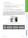
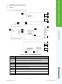
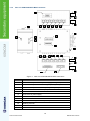
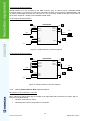
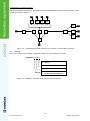
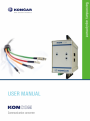
View of a KONCOM RSFO MUX transducer
9
4
10
9
12
11
4
13
15
14
16
9
1
7
2
ON
3
ON
8
10
21
22
19
17
20
18
9
10
9
6
5
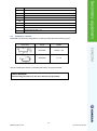
Figure 4: View of a KONCOM RSFO MUX1 transducer.
CODE
DESCRIPTION
1
An indication of presence of power supply (LED - green)
2
An indication of presence of handing Tx (LED - yellow)
3
An indication of presence of receipt Rx (LED - yellow)
4
Connector for RS232 interface (DB9)
5
Connector for RS485 and R422 interface
6
Connector for power supply
7
Micro switch S2
8
Micro switch S1
9
Holder for mounting on the rail (35 mm)
10
Earthing terminal
11
Connector for FO1 – Rx
Connector for FO1 – Tx
12
10
KONCOM USER MANUAL
KON-215-10-01.3-v.2.0-E