1
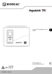
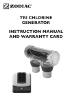
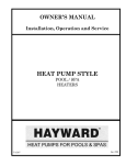
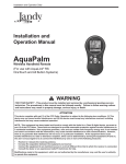
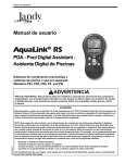
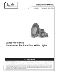
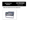
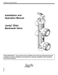
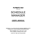
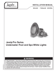
Installation and Operation Data
Installation and
Operation Manual
Jandy® Cartridge
Pool Filters
CL and CV Versa-Plumb™
b™
Series Filters
WARNING
FOR YOUR SAFETY - This product must be installed and serviced by a professional pool/
spa service technician. The procedures in this manual must be followed exactly. Improper
installation and/or operation can create dangerous high pressure which can cause the filter
lid to be blown off, possibly causing death, serious injury or property damage. Improper
installation and/or operation will void the warranty.
H0291800B
Before installing this product, read and follow all warning notices and instructions that
accompany this filter. Failure to follow warning notices and instructions may result in
property damage, serious injury, or death.
Cartridge Pool Filters - CL and CV Series Filters
Page 3
TABLE OF CONTENTS
Section 1. Safety Information ............................. 4
1.1 Important Safety Warning ............. 4
1.2 General Safety Instructions ........... 4
Section 2. General Information ........................... 5
2.1 Introduction ................................... 5
2.2 Description .................................... 5
2.3 General Requirements ................... 5
2.4 Specifications and Dimensions...... 5
Section 3. Installation Instructions...................... 6
3.1 Filter Location ............................... 6
3.2 Anchor Bracket Installation .......... 6
3.3 Filter Preparation ........................... 6
3.4 Filter Plumbing.............................. 7
3.5 Clamp Installation ......................... 9
Section 6. Maintenance ....................................... 10
6.1 General Maintenance..................... 10
6.2 Pressure Gauge .............................. 11
6.3 Cleaning the Filter Cartridge ......... 11
Section 7. Winterizing......................................... 11
Section 8. Troubleshooting ................................. 12
Section 9. Parts List and Exploded View ............ 13
9.1 Jandy® CL and CV Cartridge Filter
Parts List........................................ 13
9.2 Jandy® CL and CV Filters
Exploded View ............................. 14
Section 4. Start-Up and Operation ...................... 9
Section 10. Head Loss Curves ............................ 15
10.1 Jandy® CL and CV Cartridge Filter
Design Head Loss Curves ............. 15
Section 5. Filter Disassembly and Assembly ...... 10
Warranty ............................................................ 16
EQUIPMENT INFORMATION RECORD
DATE OF INSTALLATION
INITIAL PRESSURE GAUGE READING (WITH CLEAN FILTER)
PUMP MODEL
HORSEPOWER
FILTER MODEL
SERIAL NUMBER
NOTES:
Page 4
Section 1. Safety Information
1.1
Important Safety Warning
WARNING
• Do not connect system to an unregulated city water system or other external source of pressurized
water producing pressures greater than 35 PSI.
• Pressurized air in system can cause the filter lid to be blown off which can result in death, serious
personal injury, or property damage. Be sure all air is out of system before operating
or testing the equipment.
WARNING
MAXIMUM OPERATING PRESSURE OF THE FILTER IS 50 PSI. NEVER SUBJECT THE FILTER
TO ANY OPERATING PRESSURE EXCEEDING 50 PSI.
This filter operates under high pressure. When any part of the circulating system, i.e., filter, pump,
valve(s), clamp, etc. is serviced, air can enter the system and become pressurized when the system
is restarted. Pressurized air can cause the filter lid to be blown off which can result in death, serious
personal injury or property damage. To avoid this potential hazard, follow all of the instructions in this
manual.
WARNING
To minimize risk of severe injury or death the filter and/or pump should not be subjected to the piping
system pressurization test.
Local codes may require the pool piping system to be subjected to a pressure test. These
requirements are generally not intended to apply to the pool equipment such as filters or pumps.
Jandy pool equipment is pressure tested at the factory.
If however this WARNING cannot be followed and pressure testing of the piping system must include
the filter and/or pump BE SURE TO COMPLY WITH THE FOLLOWING SAFETY INSTRUCTIONS:
• Check all clamps, bolts, lids, lock rings and system accessories to ensure they are properly
installed and secured before testing.
• RELEASE ALL AIR in the system before testing.
• Water pressure for test must NOT EXCEED 35 PSI.
• Water temperature for test must NOT EXCEED 100°F (38°C).
• Limit test to 24 hours. After test, visually check system to be sure it is ready for operation.
Notice: These parameters apply to Jandy equipment only. For non-Jandy equipment, consult equipment manufacturer.
1.2 General Safety Instructions
ATTENTION INSTALLER:
This manual contains important information about the installation, operation and safe use of this
product. This information should be given to the owner/operator of this equipment.
1.
Use equipment only in a pool or spa installation.
2.
Before repositioning valve(s) and before beginning the assembly, disassembly, or adjustment of the clamp, or
any other service of the circulating system; (A) turn the pump off and shut off any automatic controls to ensure
the system is not inadvertently started during servicing; (B) open the air release valve; (C) wait until all pressure
is relieved (air will have stopped flowing from the air release valve).
3.
Whenever installing the filter clamp follow Section 3.4 of this manual, "Clamp Installation".
4.
Once service on the circulation system is complete, follow Section 4 of this manual, "Start-up and Operation".
5.
Maintain circulation system properly. Replace worn or damaged parts immediately.
6.
Be sure that the filter is properly mounted and positioned according to these installation instructions.
7.
Do not pressure test above 35 PSI. Pressure testing must be done by a trained pool professional.
SAVE THESE INSTRUCTIONS.
Cartridge Pool Filters - CL and CV Series Filters
Page 5
Section 2. General Information
to ease in future servicing. Barrel unions are
provided with all Jandy filters.
2.1 Introduction
This manual contains information for the proper installation and operation of the Jandy® CL and CV Series
Cartridge Filters. Procedures in this manual must be
followed exactly. To obtain additional copies of this
manual contact us at 707.776.8200 ext. 237. For address
information see back cover.
2.2 Description
Cartridge filters do not require sand or diatomaceous
earth as the filter medium. Instead, the filter contains
filter elements which are easily removed for cleaning or
replacement.
Dirty water flows into the filter tank through the water
line connected to the lower bulkhead (inlet) on the
bottom half of the tank body. It is directed through the
filter cartridge inside of the filter. The debris is collected
in the filter and the clean water flows out of the filter
through the upper bulkhead (outlet) on the bottom half
of the tank body. Clean water is returned through the
piping system to the pool.
As debris collects in the filter, the pressure will rise
and water flow to the pool will diminish. The filter will
eventually become so plugged with debris that it will be
necessary to remove the filter cartridges and clean them
with soap and water.
NOTE A filter removes dirt and other suspended particles
but does not sanitize the pool. Pool water must be
sanitized and chemically balanced for clear water.
The filtration system should be designed to meet
local health codes. At a minimum, the system should
turnover the total volume of water in your pool two to
four times in a 24 hour period.
WARNING
The maximum operating pressure for this filter is 50
psi. Never subject the filter to operating pressure
exceeding 50 psi. Operating pressures above 50 psi
can cause the lid to be blown off, which can result in
death, serious personal injury, or property damage.
6.
When performing hydrostatic pressure tests or
when testing for external leaks of the completed
filtration and plumbing system, ensure that
the maximum pressure the filtration system is
subjected to does not exceed the maximum
working pressure of any of the components
within the system.
2.4 Specifications and Dimensions
See Table 1 and Figure 1.
Table 1.
Cartridge Filter Specifications
CL/CV
340
460
580
Filter Area (ft2)
340
460
580
Max. Flow (gpm)
127
150
150
Six Hour
Capacity (gal.)
45,720
54,000
54,000
Max. Working
Pressure (psi)
50
50
50
Normal Start Up
Pressure (psi)
6-15
6-15
6-15
Dimension "A"
41 in.
41 in.
47 in.
28 in
2.3 General Requirements
1.
For best overall performance place the system as
close to the pool as possible.
2.
The filter should be located on a level concrete
slab so that the orientation of the valve outlets and
the pressure gauge are convenient and accessible
for the installation and operation of the unit.
3.
"A"
Protect the filter from the weather.
OUTLET
4.
5.
If fitting a chlorinator and/or any other device into
the filtration plumbing circuit, great care must be
exercised to ensure that the appliance is installed
in accordance with the Manufacturer’s Instructions
and any standards that may exist.
We recommend the use of barrel unions to connect
each component of the water conditioning system
18 ½ in
CV INLET
Port on
CV Model
Only
CL INLET
10 ½ in
Figure 1.
Port on
CL Model
Only
Dimensions, Jandy CL and CV Series
Cartridge Filters
Page 6
Section 3. Installation Instructions
7.
If the filter needs to be located above the water
level of the pool, it can be raised 2.5 ft. without
affecting the pump efficiency. A check valve is
recommended on the suction line to the pump.
8.
If the filter is to be installed below the water level
of the pool, isolation valves should be installed on
both the suction and return lines to prevent back
flow of pool water during any routine servicing
that may be required.
WARNING
Use equipment only in a pool or spa installation.
Do not connect system to an unregulated city water
system or other external source of pressurized water
producing pressures greater than 35 psi.
3.1 Filter Location
1.
Select a well-drained area, one that does not flood
when it rains. Damp, non-ventilated areas should
be avoided.
2.
Provide solid mounting for the filter and pump
system. Install system on a concrete slab or solid
concrete blocks to avoid risk of settlement. Do not
use sand to level the filter as the sand will wash
away. Filter systems can weigh up to 800 lbs.
3.
Install electrical controls at least five (5) feet from
the filter. This will allow enough room to stand
away from the filter during start-up.
4.
Allow sufficient clearance around the filter to
permit a visual inspection of the clamp ring (see
Fig. 2).
5.
Allow sufficient space above the filter to remove
the filter lid and filter element for cleaning and
servicing.
6.
Position the filter to safely direct water drainage.
Align the air release valve to safely direct purged
air or water.
WARNING
Water discharged from an improperly positioned filter
or valve can create an electrical hazard which can
cause death, serious injury or property damage.
3.2 Anchor Bracket Installation
In Florida, building codes require that all appliances
be securely fastened to the equipment pad in order to
withstand high wind pressures created by hurricanes.
Jandy provides an anchor bracket kit for this purpose.
Please see the Parts List in Section 9 of this manual for
the correct part number. Follow the Anchor Bracket
Installation Kit Instructions to attach the brackets to the
filter.
NOTE Anchor screws and washers for securing the
anchor bracket to the equipment pad are not
included with the filter or the anchor bracket
kit. Jandy recommends that a ¼" x 2¼" long
stainless steel Tapcon® concrete screw and
stainless steel flat washer are used to mount
each anchor bracket to the equipment pad. The
Tapcon concrete screw meets Florida building
code requirements.
After placing the filter on the equipment pad, as outlined
in Section 3.1, drill a 5/32" hole in the concrete at
each of the four brackets on the filter. (The correct size
concrete drill bit should be obtained when the concrete
screws are purchased.)
Install the Tapcon® screws and washers through each
of the four (4) anchor brackets to secure the filter to the
equipment pad. See Figure 3. Do not over-torque the
screws.
CAUTION
Maintain your pressure gauge in good working order.
The pressure gauge is the primary indicator of how
the filter is operating.
3.3 Filter Preparation
1.
Check carton for damage due to rough handling
in shipment. If carton or any filter components are
damaged, notify carrier immediately.
2.
Carefully remove the accessory package.
3.
A visual inspection of all parts should be made
now. See parts list in Section 9.
4.
With the carton in an upright position, remove the
filter tank from the carton.
5.
To mount the pressure gauge/air release assembly
to the top of the filter tank (located in the accessory
bag):
6" MINIMUM CLEARANCE
FILTER
6" MINIMUM
CLEARANCE
a.
Figure 2.
Filter Location
Place the smaller, thicker o-ring onto the
threads of the tank adapter (see Figure 4).
Slide the tank adapter through the coupling
Page 7
Cartridge Pool Filters - CL and CV Series Filters
#12x1” Stainless Steel Pan
Head Screws (Qty 2)
#12x1” Pan Head
Stainless Steel
Screw (Qty 8)
Filter Base
Drill Two 3/32” Holes
Through Filter Base
Mounting Bracket
Mounting Tab
1/4” x 2-1/4” S.S. Tapcon
Screw and S.S. Washer
Drill 5/32” Hole
Anchor
Bracket
(Qty 4)
Tank Bottom
3-1/2” Thick
(Min.)
Concrete Pad
Filter Tank Anchor Bracket Installation
Figure 3.
Anchor Bracket to Platform Installation
Anchor Bracket Installation
Housing
O-Ring
Tank Adapter
Tank Adapter to Housing
Coupler
3.
Place the filter on the concrete pad, lined up with
the inlet/outlet pipes (see Figures 5 and 5A).
4.
To reduce pressure losses, 2" (minimum) piping is
recommended for plumbing the system.
5.
For best efficiency use the fewest possible number
of fittings. This will prevent a restriction in the
water flow.
6.
Make all plumbing connections in accordance
with local plumbing and building codes. Filter
connections are provided with an o-ring seal. To
avoid damage to the o-rings, use only a silicone
base lubricant on the o-rings. Do not use pipe joint
compound, glue or solvent on inlet/outlet union
coupling nuts.
7.
Keep piping tight and free of leaks. Pump suction
line leaks may cause air to be entrapped in filter
tank or loss of prime at the pump. Pump discharge
line leaks may show up as dampness or jets of
water.
8.
Support the inlet/outlet pipes independently to
prevent any undue strains on the filter valve.
9.
Connect the pipes using the unions supplied with
the filter. Do not use teflon tape or pipe dope on
any unions. Assemble the unions dry and hand
tighten. See Figure 6.
O-Ring
Figure 4.
b.
c.
Pressure Gauge/Air Release Assembly
nut and into the filter tank. Use the flats
on the tank adapter to tighten. Do not
overtighten.
Place the larger, thinner o-ring onto the
gauge housing. Thread the housing into the
coupler on the tank adapter.
Orient the gauge/air release assembly in the
desired position. Raise and thread the locknut
onto the bottom of the gauge/air release
assembly. Hand tighten the nut only. Using
a wrench to tighten the nut may damage the
nut, gauge or air release assembly.
3.4 Filter Plumbing
1.
2.
This filter operates under pressure. When clamped
properly and operated without air in the water
system, this filter will operate in a safe manner.
If the system can be subjected to higher pressure
than the maximum rating of any component,
install an ASME approved automatic pressure
relief valve or pressure regulator in the circulation
system. Set the relief valve or pressure regulator to
lowest working pressure of any of the components
in the system.
10. If desired, the CV filter drain can be plumbed
using a Jandy universal union. The plumbing must
contain a ball valve as shown in Figure 6.
CAUTION
Be sure that all provisions for wastewater disposal
meet local, state or national codes. During any
draining process, one hundred gallons (100 gals.)
or more of pool water will be discharged. CL and CV
(Cartridge) Filters are not subject to backwashing.
Do not discharge water where it will cause flooding
or damage.
Page 8
From Outlet Port
Jandy Heater
Spa Make Up
To Inlet Port
Jandy
Check
Valve
Waterfall
Jandy Pump
Jandy Filter
From Pool
Drain
Spa Return
Pool Return
Spa Suction
From Pool Skimmer
Figure 5.
CL Cartridge Filter Plumbing for Pool/Spa Combination
Inlet Port
Outlet Port
Jandy Heater
Jandy Pump
Spa Make Up
Jandy Filter
From Pool
Drain
Jandy
Check
Valve
Waterfall
Spa Suction
Spa Return
Pool Return
From Pool Skimmer
Figure 5A. CV Cartridge Filter Plumbing for Pool/Spa Combination
CL/CV Filter
Tank Bottom
Cap
Nut
2" Ball
Valve
2" Pipe
OR
O-ring
Bulkhead
Figure 6.
Alt Universal Union
for Plumbing
Jandy CL and CV Series Cartridge Filter Drain Configurations
Cartridge Pool Filters - CL and CV Series Filters
Page 9
2.
Check that the drain plug for CL filters or drain
cap for CV filters is in place and tight.
3.
Check that the tank clamp is correctly seated and
tight (See Figs. 7 and 8).
WARNING
Clamp Ring
"T" Nut and
Threaded Rod
Figure 7.
NEVER start pump while standing
within five (5) feet of the filter. Starting
the pump while there is pressurized air
in the system can cause the filter lid to
be blown off, which can cause death,
serious personal injury or property
damage.
Tightening Nut
w/ Shoulder
WARNING
NEVER operate the filter system at
more than 50 psi of pressure. Operating
the filter system in excess of 50 psi can
cause the filter lid to be blown off, which
can cause death, serious personal
injury or property damage.
Filter Clamp Ring
3.5 Clamp Installation
1.
Be certain the o-ring is in position in the lower
tank half. Press the filter lid over the lower half
sandwiching the o-ring between the two halves.
2.
Holding the ends of the filter clamp apart, position
the hinged segment of the filter clamp over both
upper and lower tank flanges. Bring the ends of the
filter clamp together.
3.
Place the "T" nut and threaded rod assembly into
the clamp. Be sure the "T" nut is seated in the
clamp in the proper orientation (See Fig. 7).
4.
Use a 9/16" socket on the tightening nut until the
clamp ring halves touch each other, or are within
1/16" (See Fig. 7) but do not overtighten as the
clamp can break. If unable to tighten as indicated,
do not operate the filter and call a service
technician immediately.
5.
6.
After the first week of operation, check the clamp
and retighten if necessary.
CAUTION
DO NOT operate filter at water temperatures above
105° F (40.6° C). Water temperatures above the
manufacturer's recommendations will shorten the life
span of the filter and void the warranty.
4.
Open the pump hair/lint pot lid and fill the pump
basket with water to prime the system. Replace the
lid. (You may have to do this several times on new
and seasonal start-ups.)
5.
Completely open the air release valve on the
gauge/air release assembly by turning the knob on
the back of the assembly fully counterclockwise
(do not remove the knob).
6.
Be sure to open any filter isolation valves that
were installed in the system.
7.
Stand clear of the filter and start the pump to
circulate water through the system. When a steady
stream of water starts to come out of the air release
valve, close the valve.
8.
Watch the pressure gauge to be sure that the
pressure does not exceed 50 psi (with clean
cartridges). If the pressure approaches 50 psi,
immediately turn the pump off and clean the
filter cartridges (see Section 6.3). If the pressure
remains high after cleaning the filter, refer to the
troubleshooting guide in Section 8 for possible
causes and solutions.
Check the filter clamp at least once a month.
WARNING
Follow these instructions carefully.
Improper clamp installation can cause
the filter lid to be blown off, which can
result in death, serious personal injury,
or property damage.
Section 4. Start-Up and Operation
NOTE This section applies to both new pool and
seasonal start-up.
1.
Turn off the pump. Switch off the circuit breaker
to the pump motor.
Page 10
"T" Nut
Threaded
Rod
Tightening
Nut w/
Shoulder
Tightening
Nut w/
Shoulder
Clamp
Ring
2.
IMPORTANT: Completely open air release valve
on top of the filter tank to release all pressure
from inside the tank and system.
3.
Close the filter isolation valves on the system to
prevent flooding.
4.
Remove the drain plug located at the bottom of the
filter tank and allow the tank to drain.
5.
Replace the drain plug.
6.
Loosen the tank clamp ring retainer and remove
the clamp ring.
7.
Remove the top of the filter tank by lifting it
straight up until it clears the cartridges on the
inside of the tank.
8.
Remove the manifold assembly by lifting it off of
the outlet tube and out of the tank.
9.
Pull the cartridges out of the filter tank and clean
the cartridge using the instructions in Section 6.3.
Use a 9/16" Socket
Clamp Ring,
Closed Position
GAP NOT TO EXCEED
1/16"
Figure 8.
9.
Filter Clamp Ring Assembly
After the pressure gauge has stabilized, turn the
bezel ring so that the arrow next to the word
"CLEAN" aligns with the needle of the gauge. As
the filter cleans the water, and the cartridges begin
to clog the pressure begins to increase. When the
needle of the pressure gauge aligns with the arrow
next to the word "DIRTY" on the bezel, it is time
to clean the filter (see Section 6.3). This indicates
an increased pressure of between 10 and 12 psi
above original starting pressure.
10. Using new cartridges or the clean original ones,
place the cartridges back into the filter tank. Be
sure that they are correctly seated on the cartridge
support on the bottom of the tank.
11. Inspect the o-ring at the top of the outlet tube for
cracks and wear marks. Replace if necessary.
12. Reinstall the manifold making sure that it fits
squarely over the cartridges and outlet tube.
13. Inspect the tank o-ring for cracks or wear marks.
Replace if necessary. Place the o-ring back onto
the filter bottom.
14. Place the filter lid onto the filter tank bottom.
15. Replace the tank clamp ring. See Section 3.4 for
clamp installation.
16. Start the pump by following the procedures
outlined in steps 2 through 7 of Section 4.1.
Section 5. Filter Disassembly and
Assembly
Section 6. Maintenance
6.1 General Maintenance
WARNING
NEVER attempt to assemble,
disassemble or adjust the filter when
there is pressurized air in the system.
Starting the pump while there is
any pressurized air in the system
can cause the filter lid to be blown
off, which can cause death, serious
personal injury or property damage.
1.
Turn off the pump. Switch off the circuit breaker
to the pump motor.
1.
Wash outside of filter with a mild detergent and
water. Rinse off with a hose. Do not use solvents
to clean the filter, solvents will damage the plastic
components of the filter.
2.
Check pressure during operation at least once a
week.
3.
Remove any debris from the skimmer basket and
hair/lint pot on pump.
4.
Check pump and filter for any leaks. If any leaks
develop, turn off the pump and call a qualified
pool service technician.
Cartridge Pool Filters - CL and CV Series Filters
5.
6.
7.
Product safety signs or labels should be
periodically inspected and cleaned by the product
user as necessary to maintain good legibility for
safe viewing distance.
Product safety signs or labels should be replaced
by the product user when a person with normal
vision, including corrected vision, is no longer
able to read the safety signs or label message panel
text at a safe viewing distance from the hazard.
In cases where the product has an extensive
expected life or is exposed to extreme conditions,
the product user should contact either the product
manufacturer or some other source to determine
means for obtaining replacement signs or labels.
Installation of new replacement safety signs or
labels should be in accordance with the sign or
label manufacturer's recommended procedure.
6.2 Pressure Gauge
1.
During operation of the filtration system, check
the pressure gauge/air release assembly for air or
water leaks at least once a week.
2.
Keep the pressure gauge in good working order.
If you suspect a problem with the gauge, Jandy
recommends you call a qualified service technician
to do any work on the filter/pump system.
CAUTION
Maintain your pressure gauge in good working order.
The pressure gauge is the primary indicator of how
the filter is operating.
6.3 Cleaning the Filter Cartridge
1.
Follow the procedures outlined in steps 1 through
8 of Section 5.1 to expose the cartridge elements
inside the filter.
2.
Remove cartridge elements and place them upright
in an area suitable for washing.
3.
Use a garden hose and nozzle to wash each pleat
of each element.
NOTE Algae, suntan oil, calcium and body oils can form
coatings on filter element which may not be removed
by normal hosing. To remove such materials, soak
the element in de-greaser and then a de-scaler. Your
local pool dealer will be able to recommend suitable
products.
Page 11
4.
Inspect each cartridge for holes, tears or
excessively worn pleats. Replace if necessary.
5.
To reassemble the filter with the new or clean
cartridges follow the procedure outlined in steps
10 through 16 of Section 5.
Section 7. Winterizing
1.
Turn off the pump and circuit breakers.
2.
Open air release valve on top of the filter.
3.
Remove the drain plug at the base of the filter to
ensure that the tank is empty. Store the drain plug
and seal in a safe place. Do not reinstall until next
season at start-up.
4.
Drain system piping of all water.
5.
Cover the system with a tarpaulin or plastic sheet
to protect it from the weather.
Page 12
Section 8. Troubleshooting
1.
For a list of common problems and solutions see
the Troubleshooting Guide below.
2.
Jandy recommends that you call a qualified service
technician to do any work on the filter/pump
system. For technical service call 707.776.8200,
ext. 260.
Table 2.
Troubleshooting Guide
Fault Symptom
Water is not clear.
Low water flow.
Short filter cycles.
High pressure on start-up.
Dirt returns to pool.
Possible Problems
Solutions
Insufficient disinfectant level.
Check and adjust disinfectant level.
Incorrect pool chemistry.
Test and adjust water chemistry.
Heavy bathing and/or dirt loads.
Adjust filter time and/or water chemistry.
Insufficient running times.
Increase pump run time.
Filter is dirty.
Clean filter cartridges per instructions.
Hole in filter element.
Replace cartridge.
Filter system strainer baskets dirty.
Check and clean strainer baskets.
Air leaks on suction side of pump.
Check all connections between pool intake
and pump.
Restrictions or blockage in either suction or
return lines.
Check all lines for debris or partially closed
valves.
Filter cartridges need to be cleaned or
replaced.
Clean or replace filter cartridges per
instructions.
Pool water level too low.
Fill pool so level is above pump inlet line.
Pump not primed.
Fill pump with water at basket and replace lid.
Pump impeller vanes blocked.
Technician required.
Strainer baskets not being used and/or
broken. (Allow debris into pump.)
Replace baskets.
Pump operating under speed (low voltage).
Technician or electrician required.
Presence of algae clogging filter.
Check disinfectant content.
Incorrect water chemistry.
Check pH, total alkalinity and TDS.
Pump output exceeds design flow rate of
filter.
Check pump performance.
Ineffective cleaning.
Clean or replace filter cartridge per
instructions.
Small eyeball fitting in Pool/Spa.
Replace with larger diameter fitting.
Partially closed valve on return line.
Check and fully open all valves on return line.
Too large of pump.
Check pump and filter selection.
Filter cartridges dirty.
Clean filter cartridges per instructions.
Hole in filter cartridge.
Replace filter cartridge per instructions.
Worn o-ring seal inside filter.
Replace o-ring.
Cartridge Pool Filters - CL and CV Series Filters
Page 13
Section 9. Parts List and Exploded
View
9.1 Jandy® CL and CV Cartridge Filter Parts
List
Key
No.
Model No.
Part No.
1
Handle Assembly w/ hardware (set of 2)
Description
All
R0357100
2
Handle Hardware (set of 4)
All
R0359900
3
Gauge/Air Release Assembly
All
R0357200
4
Pressure Gauge
All
R0569600
5
Tank Adapter w/O-ring - Union
All
R0552000
6
Tank Top
580
R0357300
Tank Top
340,460
R0554700
All
R0357700
7
Top Spacer
8
Breather Tube Assembly
All
R0358700
9
Manifold Assembly
All
R0357600
10
Filter Cartridge, 145 sq. ft. (4 required)
580
R0357900
Filter Cartridge, 115 sq. ft. (4 required)
460
R0554600
Filter Cartridge, 85 sq. ft. (4 required)
340
R0554500
11
Tank Clamp Ring w/Rod Assembly
All
R0357400
12
Threaded Rod and Retainer
All
R0357500
13
Tank O-ring
All
R0357800
14
Outlet Tube/Elbow Assembly w/O-rings
580
R0358100
Outlet Tube/Elbow Assembly w/ O-rings
340,460
R0555100
15
Inlet Elbow w/O-ring
All
R0358400
16
Filter Cartridge Support
All
R0358500
17
O-ring Replacement Kit (not shown)
All
R0358000
18
Ring, Retaining
All
R0405200
19
Bulkhead Assembly w/O-ring, CV Filter
All
R0465600
20
Anchor Bracket (Qty 4)
All
R0465500
21
Tank Bottom Assembly, CV Filter
All
R0465400
22
Tank Bottom Assembly, CL Filter
All
R0466500
23
Universal Half Unions (Set of 3) and
Drain Plug Cap
All
R0461800
Page 14
9.2 Jandy® CL and CV Filters Exploded View
CL Filter
CV Filter
,22
16
,21
16
22,18
18,21
14
14
22
21
21
15,21
22
19
19
20
20
21
15,22
22
23
21
23
Cartridge Pool Filters - CL and CV Series Filters
Page 15
Section 10. Head Loss Curves
10.1 Jandy® CL and CV Cartridge Filter Design
Head Loss Curves
CL340 CV340
CL460 CV460
CL580 CV580
28
26
24
22
20
Design
18
Head
16
Loss
(ft head) 14
12
10
8
6
4
2
0
12
10
8
6
4
2
0
0
30
60
90
Flow Rate (gpm)
120
150
Design
Pressure
Drop
(psi)
LIMITED WARRANTY
Thank you for purchasing Jandy® pool and spa products. Jandy Pool Products, Inc. warrants all parts to be free
from manufacturing defects in materials and workmanship for a period of one year from the date of retail
purchase, with the following exceptions:
• AquaLink® RS units installed with Jandy Surge Protection Kits will be covered for two years.
• NeverLube® valves are warranted for the life of pool and/or spa on which they were originally installed.
• AquaPureTM Electronic Chlorine Generator Electrolytic Cells carry a 5 year limited warranty on a prorated basis.
This warranty is limited to the first retail purchaser, is not transferable, and does not apply to products that have
been moved from their original installation sites. The liability of Jandy Pool Products, Inc. shall not exceed the
repair or replacement of defective parts and does not include any costs for labor to remove and reinstall the
defective part, transportation to or from the factory, and any other materials required to make the repair. This
warranty does not cover failures or malfunctions resulting from the following:
1. Failure to properly install, operate or maintain the product(s) in accordance with our published Installation,
Operation and Maintenance Manuals provided with the product(s).
2. The workmanship of any installer of the product(s).
3. Not maintaining a proper chemical balance in your pool and/or spa [pH level between 7.2 and 7.8, Total
Alkalinity (TA) between 80 to 120 ppm, Total Dissolved Solids (TDS) less than 2000 not including salt ppm].
4. Abuse, alteration, accident, fire, flood, lightning, rodents, insects, negligence or acts of God.
5. Scaling, freezing, or other conditions causing inadequate water circulation.
6. Operating the product(s) at water flow rates outside the published minimum and maximum specifications.
7. Use of non-factory authorized parts or accessories in conjunction with the product(s).
8. Chemical contamination of combustion air or improper use of sanitizing chemicals, such as introducing
sanitizing chemicals upstream of the heater and cleaner hose or through the skimmer.
9. Overheating; incorrect wire runs; improper electrical supply; collateral damage caused by failure of O-Rings,
DE grids, or cartridge elements; or damage caused by running the pump with insufficient quantities of water.
LIMITATION OF LIABILITY:
This is the only warranty given by Jandy Pool Products, Inc. No one is authorized to make any other warranties
on behalf of Jandy Pool Products, Inc. THIS WARRANTY IS IN LIEU OF ALL OTHER WARRANTIES,
EXPRESSED OR IMPLIED, INCLUDING BUT NOT LIMITED TO ANY IMPLIED WARRANTIES OF FITNESS
FOR A PARTICULAR PURPOSE AND MERCHANTABILITY. JANDY POOL PRODUCTS, INC. EXPRESSLY
DISCLAIMS AND EXCLUDES ANY LIABILITY FOR CONSEQUENTIAL, INCIDENTAL, INDIRECT OR
PUNITIVE DAMAGES FOR BREACH OF ANY EXPRESSED OR IMPLIED WARRANTY. This warranty gives
you specific legal rights. You may also have other rights which vary by state or province.
H0291800B
WARRANTY CLAIMS:
For prompt warranty consideration, contact your dealer and provide the following information: proof of purchase,
model number, serial number and date of installation. The installer will contact the factory for instructions
regarding the claim and to determine the location of the nearest designated service center. If the dealer is not
available, you can locate a service center in your area by visiting www.jandy.com or by calling our technical
support department at (707) 776-8200 extension 260. All returned parts must have a Returned Material
Authorization number to be evaluated under the terms of this warranty.
6000 Condor Drive, Moorpark, CA, USA 93021 • 707.776.8200 FAX 707.763.7785
Jandy Pool Products, Inc.
in U.S.A. © 2007 Jandy Pool Products, Inc. 0711
6000 Condor Drive • Moorpark, CA USA 93021Litho
• 707.776.8200
• Fax 707.763.7785
For technical support call 707.776.8200, ext. 260