1
2 ASSEMBLER
Figure 2-0.
Table 2-0.
Listing 2-0.
Listing 2-0.
Overview
The easmTS.exe assembler runs from an operating system command line
or from the VisualDSP++ environment. The assembler processes assembly
source, data, header files, and produces an object file. Assembler operations depend on two types of controls: assembler directives and assembler
switches.
Assembler directives are coded in your assembly source file. The directives
let you define and initialize variables, set up hardware features, and identify program’s sections * for placement within DSP memory. The
assembler uses directives for guidance as it translates a source program into
object code.
Assembler switches are specified on the operating system’s command line
or in the Assemble tab of the VisualDSP++ environment’s Project
Options dialog box. These switches allow you to control the assembly process of source, data, and header files. You also use these switches to select
assembler’s features, such as search paths, output file names, and macro
preprocessing, among others.
This chapter provides information that you need to know when developing and assembling programs for the TigerSHARC DSPs.
* The assembler section (or .SECTION) declaration referred to here corresponds to a linker input sec-
tion.
VisualDSP++ 2.0 Assembler & Preprocessor Manual for TigerSHARC DSPs 2-1
Overview
The chapter contains the following information about the assembler:
• “Assembler Guide” on page 2-3
• “Assembler Command-Line Reference” on page 2-16
• “Assembler Syntax Reference” on page 2-27
• “Assembler Glossary” on page 2-70
2-2 VisualDSP++ 2.0 Assembler & Preprocessor Manual for TigerSHARC DSPs
Assembler
Assembler Guide
The guide section describes the process of developing new programs in
the ADSP-TSxxx DSPs’ assembly language. This section provides information that you need to know when assembling your programs from the
operating system’s command line.
Software developers using the assembler should be familiar with the following operations:
• “Writing Assembly Programs” on page 2-3
• “Preprocessing a Program” on page 2-13
• “Reading a Listing File” on page 2-14
• “Setting Assembler Options” on page 2-15
For information about the DSP architecture, including the DSP instruction set that you use when writing assembly programs, see the hardware
and instruction set manuals.
Writing Assembly Programs
Write your assembly language programs using the VisualDSP++ editor or
any editor that produces text files. Do not use a word processor that
embeds special control codes in the text. Append an .ASM extension to
source file names to identify them as assembly source files.
Assemble your source files, either using the assembler’s command line or
from the VisualDSP++ environment. In the default mode of operation,
the assembler processes an input file through the listed stages to produce a
binary object file (.DOJ) and an optional listing file.
Object files serve as input to the linker when you link your executable program. These files are in Executable and Linkable Format (ELF), an
industry-standard format for object files. In addition, the assembler can
VisualDSP++ 2.0 Assembler & Preprocessor Manual for TigerSHARC DSPs 2-3
Assembler Guide
embed binary information in Debugging Information Format
(DWARF-2) for source level debugging.
Listing files are text files that you can read for information on the results
of the assembly process.
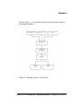
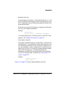
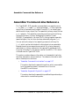
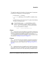
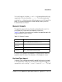
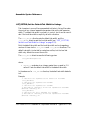
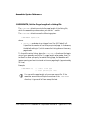
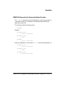
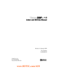
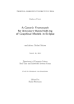
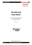
Figure 2-1 on page 2-5 shows a graphical overview of the assembly process. The figure shows the preprocessor processing the assembly source
(.ASM) and initialization data (.DAT) files. The assembly source file often
contains preprocessor commands, such as #include, that cause the preprocessor to include header files ( .H) into your source program. The
preprocessor’s only output, an intermediate source file (.IS), is the assembler’s primary input.
2-4 VisualDSP++ 2.0 Assembler & Preprocessor Manual for TigerSHARC DSPs
Assembler
A binary object (.DOJ) file and an optional listing file are final results of
the successful assembly.
Data initialization file
(.DAT)
Header file
(.H)
Assembly source file
(.ASM)
Preprocessor
Intermediate
preprocessed file
(.IS)
Assembler
Object file
(.DOJ)
Listing file
()
Figure 2-1. Assembler Input & Output Files
VisualDSP++ 2.0 Assembler & Preprocessor Manual for TigerSHARC DSPs 2-5
Assembler Guide
Program Content
Statements within an assembly source file are comprised of assembly
instructions, assembler directives, and preprocessor commands. Instructions assemble to executable code, while directives and commands modify
the assembly process. The syntax of these statement types are as follows:
• Assembly instructions
Instructions follow the DSP’s instruction set syntax documented in
the DSP’s user manuals. Each instruction begins with a keyword
and ends it with a semicolon (;). You may put up to four instructions on a line; instructions on the same line must be delimited by
a single semicolon. Multiple instruction lines end with a double
semicolon (;;).
For program reference purposes (such as a CALL), you can place an
address label at the beginning of an instruction line or on the preceding line. End the label with a colon ( :) before beginning the
instruction. You can then refer to this memory location in your program using the label instead of an absolute address. Although there
is no length restriction when defining labels, it is convenient to limit
them to the length of a screen line, typically eighty characters.
Labels are sensitive to case. So, the assembler treats “outer” and
“Outer” as unique labels.
Example:
outer: r0=r1+r2;;
start: if naeq jump error;;
2-6 VisualDSP++ 2.0 Assembler & Preprocessor Manual for TigerSHARC DSPs
Assembler
• Assembler directives
Directives begin with a period (.) and end with a semicolon (;). The
period must be the first character on the line containing your directive. The assembler does not differentiate between directives in lowercase and uppercase.
Note that this manual prints directives in uppercase to distinguish
them from other assembly statements.
Example:
.SECTION data1;
.VAR sqrt_coeff[2] = 0x00000001, 0x00000002;
For complete description of the directive set for the ADSP-TSxxx
assembler, see “Assembler Directives” on page 2-38.
• Preprocessor commands
Preprocessor commands begin with a pound sign (#) and end with
a carriage return. The pound sign must be the first character on the
line containing the command. If the command is longer than one
line, use a backslash (\) and a carriage return to continue the command on the next line. Do not put any characters between the backslash and the carriage return. Unlike assembly directives,
preprocessor commands are case-sensitive and must be lowercase.
For a list of the preprocessor commands, see “Preprocessor Commands” on page 3-16.
Example:
#include "string.h"
#define MAX 100
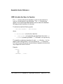
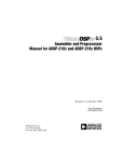
Figure 2-2 on page 2-9 contains a sample assembly source file.
VisualDSP++ 2.0 Assembler & Preprocessor Manual for TigerSHARC DSPs 2-7
Assembler Guide
Program Structure
An assembly source file must describe how code and data are mapped into
the memory on your target DSP. The TigerSHARC architecture has unified memory map in which the partition between program memory and
data memory is user-determined.
The way you structure your code and data into memory should agree with
the corresponding Linker Description File required for every DSP project.
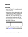
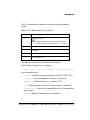
In the assembly language source, the mapping of code and data is accomplished using the .SECTION directive. The .SECTION directive defines
groupings of instructions and data that are set as contiguous memory
addresses in the DSP. Each .SECTION name corresponds to an input section name in the Linker Description File (.LDF). Some suggested section
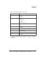
names that you could use in your assembly source appear in Table 2-1.
Using these predefined names in your sources makes it easier to take
advantage of the default Linker Description File included in your DSP
system. For more information on the LDF, see the Linker & Utilities Manual for TigerSHARC Family DSPs.
Table 2-1. Suggested Input Section Names
.SECTION Name
Description
data1
A section that holds data in Memory Block M1.
data2
A section that holds data in Memory Block M2.
program
A section that holds code in Memory Block M0.
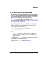
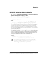
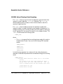
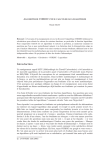
You can create sections in a program by grouping elements to meet hardware constraints. To group code that reside in off-chip memory, declare a
section for that code and place that section in the selected memory with
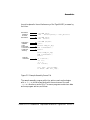
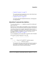
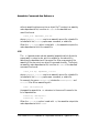
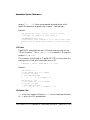
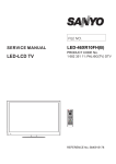
the linker. Figure 2-2 on page 2-9 shows how a program divides into sec-
2-8 VisualDSP++ 2.0 Assembler & Preprocessor Manual for TigerSHARC DSPs
Assembler
tions to be placed in the unified memory of the TigerSHARC processor by
the linker.
Data Section
Assembler
Directive
Data Section
.SECTION data1;
.VAR
buffer1[0x100] = "data_buf.dat";
Code Section
Assembler
Label
Preprocessor
Commands for
Conditional
.SECTION program;
start:
Assembly
.SECTION data2;
.VAR
buffer2;
#ifndef XRO_SET_TO_2
XR0 = 0x00000001;;
#endif
#ifdef XRO_SET_TO_2
XRO = 0x00000002;;
#endif
Assembly
Instructions
J1 = buffer1;;
JL1 = 0;;
J2 = 1;;
LC0 = 0x100;;
this_loop: [J1+=J2]=XRO;;
IF NLC0E, JUMP this_loop;;
Figure 2-2. Example Assembly Source File
The sample assembly program splits into sections; each section begins
with a .SECTION directive and ends with the occurrence of the next
.SECTION directive or end-of-file. The source program contains two data
and one program sections, as follows:
VisualDSP++ 2.0 Assembler & Preprocessor Manual for TigerSHARC DSPs 2-9
Assembler Guide
• Data Sections — data1 and data2 — variables and buffers are
declared and can be initialized.
• Program Section — program — instructions, including statements
for conditional assembly are coded in program sections.
Looking at this code sample, notice that an assembly source often contains
preprocessor commands, such as #include for inclusions of other files in
your source code, #ifdef for conditional assembly, or #define for macro
definitions. The assembler directives, such as .VAR, appear within a section
to declare and initialize variables.
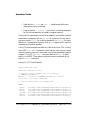
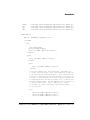
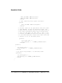
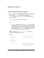
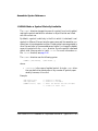
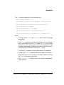
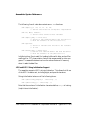
Listing 2-1shows a sample user-defined Linker Description File. Looking
at the LDF’s SECTIONS{} command, notice that the input sections’ names
match the memory sections’ names used in the following assembly sample
program. The LDF’s SECTIONS{} command defines the .SECTION placements in the ADSP-TSxxx system’s physical memory as defined by the
linker’s Memory{} command.
Listing 2-1. LDF Code Example
ARCHITECTURE(ADSP-TS001)
SEARCH_DIR( $ADI_DSP\TS\lib )
// Libraries from the command line are included in
// COMMAND_LINE_OBJECTS.
$OBJECTS = TS_hdr.doj, $COMMAND_LINE_OBJECTS, libc.dlb,
libsim.dlb, TS_exit.doj, libcpp.dlb;
// Internal memory blocks are 0x10000 (64k)
MEMORY
{
M0Code
M1Data
M1Heap
M1Stack
M2Data
M2Stack
{TYPE(RAM)
{TYPE(RAM)
{TYPE(RAM)
{TYPE(RAM)
{TYPE(RAM)
{TYPE(RAM)
START(0x00000000)
START(0x00080000)
START(0x0008C000)
START(0x0008C800)
START(0x00100000)
START(0x0010C000)
END(0x0000FFFF)
END(0x0008BFFF)
END(0x0008C7FF)
END(0x0008FFFF)
END(0x0010BFFF)
END(0x0010FFFF)
WIDTH(32)}
WIDTH(32)}
WIDTH(32)}
WIDTH(32)}
WIDTH(32)}
WIDTH(32)}
2-10 VisualDSP++ 2.0 Assembler & Preprocessor Manual for TigerSHARC DSPs
Assembler
SDRAM
MS0
MS1
HOST
{TYPE(RAM)
{TYPE(RAM)
{TYPE(RAM)
{TYPE(RAM)
START(0x04000000)
START(0x08000000)
START(0x0C000000)
START(0x10000000)
END(0x07FFFFFF)
END(0x0BFFFFFF)
END(0x0FFFFFFF)
END(0xFFFFFFFF)
WIDTH(32)}
WIDTH(32)}
WIDTH(32)}
WIDTH(32)}
}
PROCESSOR p0
{
OUTPUT( $COMMAND_LINE_OUTPUT_FILE )
SECTIONS
{
code
{
FILL(0xb3c00000)
INPUT_SECTION_ALIGN(4)
INPUT_SECTIONS( $OBJECTS(program))
} >M0Code
data1
{
INPUT_SECTIONS( $OBJECTS(data1))
} >M1Data
data2
{
INPUT_SECTIONS( $OBJECTS(data2))
} >M2Data
//
//
//
//
//
//
//
//
//
//
Provide support for initialization, including C++
static initialization. This section builds a table of
initialization function pointers. These functions are
called in order before the main routine is entered. The
order is determined by the linker section in which the
function pointer has been defined: the C library uses
ctor0 through ctor3, and the compiler uses ctor for C++
static initializers. The C library uses several
sections to satisfy ordering requirements among
initializers.
ctor
{
INPUT_SECTIONS( $OBJECTS(ctor0))
INPUT_SECTIONS( $OBJECTS(ctor1))
INPUT_SECTIONS( $OBJECTS(ctor2))
VisualDSP++ 2.0 Assembler & Preprocessor Manual for TigerSHARC DSPs 2-11
Assembler Guide
INPUT_SECTIONS( $OBJECTS(ctor3))
INPUT_SECTIONS( $OBJECTS(ctor))
} >M1Data
// Table containing heap segment descriptors
heaptab
{
INPUT_SECTIONS( $OBJECTS(heaptab))
} >M1Data
//
//
//
//
//
//
//
//
Allocate stacks for the application. Note that stacks
grow downward, and must be quad-word aligned. This
means that the location just after the highest word of
the stack is quad-word aligned (evenly divisible by 4).
There are two labels for each stack: "*_base" is the
location just ABOVE the top of the stack, and "*_limit"
is the lowest word that is part of the stack. Each stack
occupies all of its own memory block.
jstackseg
{
ldf_jstack_limit = .;
ldf_jstack_base = . + MEMORY_SIZEOF(M1Stack);
} >M1Stack
kstackseg
{
ldf_kstack_limit = .;
ldf_kstack_base = . + MEMORY_SIZEOF(M2Stack);
} >M2Stack
// The default heap occupies its own memory block
defheapseg
{
ldf_defheap_base = .;
ldf_defheap_size = MEMORY_SIZEOF(M1Heap);
} >M1Heap
}
}
2-12 VisualDSP++ 2.0 Assembler & Preprocessor Manual for TigerSHARC DSPs
Assembler
Program Interfacing Requirements
At some point, you may want to interface your assembly program with a C
or C++ program. For information on a particular compiler’s run-time
environment, see the compiler’s user manual. The definition of the
run-time environment for the TigerSHARC C/C++ compiler is provided
in the C/C++ Compiler & Library Manual for TigerSHARC Family DSPs,
which also includes a series of examples to demonstrate how to mix C/C++
and assembly code.
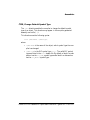
Preprocessing a Program
The assembler includes a preprocessor that allows you to use C-style preprocessor commands in your assembly source files. The preprocessor
automatically runs before the assembler unless you use the assembler’s -sp
(skip preprocessor) switch. Table 3-3 on page 3-16 lists preprocessor commands and provides a brief description of each command.
Preprocessor commands are useful for modifying assembly code. For
example, you can use the #include command to fill memory, load configuration registers, and set up DSP parameters. You can use the #define
command to define constants and aliases for frequently used instruction
sequences. The preprocessor replaces each occurrence of the macro reference with a corresponding value or series of instructions. For example, the
macro MAX in the example on page 2-7 is replaced with the number 100
during preprocessing.
Note that the preprocessor also automatically removes all comments from
assembler-generated optional listing files.
For more information on the preprocessor command set, see “Preprocessor Commands” on page 3-16.
VisualDSP++ 2.0 Assembler & Preprocessor Manual for TigerSHARC DSPs 2-13
Assembler Guide
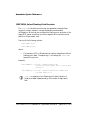
Reading a Listing File
A listing file is an optional output text file that lists the results of the
assembly process. You should always specify the full name of the listing
file. Listing files provide the following information:
• Address — The first column contains the offset from the .SECTION’s
base address.
• Opcode — The second column contains the hexadecimal opcode
that the assembler generates for the line of assembly source.
• Line — The third column contains the line number in the assembly
source file.
• Assembly Source — The fourth column contains the assembly
source line from the file.
Assembler listings are based on the original source files, not the preprocessed source file. Each line of the original source files, including
comments, will appear in the assembly source column of the listing file.
There are listing directives to control which source files and source file
lines will be included in the listing (see “Assembler Directives” on page
2-38).
For included files, the source line numbers have two parts separated by a
'.'. The first part indicates the include nesting level, while the second part
is the line number. For example, the line number "2.15" indicates line 15
in an include file nested two levels deep. Line numbers for the top-level
source file do not indicate the nesting level. When the listing enters or
leaves a nested source file, the listing will contain an extra line which gives
the name of the source file that is being entered or returned to.
2-14 VisualDSP++ 2.0 Assembler & Preprocessor Manual for TigerSHARC DSPs
Assembler
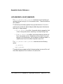
Setting Assembler Options
When developing a DSP project, you may find it useful to modify the
assembler’s default options settings. The way you set the assembler’s
options depends on the environment used to run the DSP development
software:
• From the operating system command line, you use the assembler’s
command-line switches. For more information on these switches,
see the “Assembler Command-Line Interface” on page 2-17.
• Within the VisualDSP++ environment, you set the assembler’s
options in the VisualDSP++ Integrated Development and Debugging Environment (IDDE). For more information on these option
settings, see the VisualDSP++ 2.0 User's Guide for TigerSHARC DSPs.
VisualDSP++ 2.0 Assembler & Preprocessor Manual for TigerSHARC DSPs 2-15
Assembler Command-Line Reference
Assembler Command-Line Reference
The TigerSHARC DSP assembler processes data from assembly source
(.ASM), data (.DAT), header (.H), and preprocessed (.IS) files to generate
object files in Executable and Linkable Format (ELF), an industry-standard format for binary object files. The assembler’s primary output file has
a .DOJ extension. The assembler’s secondary outputs are optional listing
files and information in binary Debugging Information Format
(DWARF-2) embedded in the object file. By linking together separately
assembled object files, the linker produces executable programs (.DXE).
You can archive the output of an assembly process into a library file
(.DLB), which can then be linked with other objects into an executable.
Because the archive process performs a partial link, placing frequently
used objects in a library reduces the time required for subsequent links.
For more information on the archiver, see the VisualDSP++ 2.0 Linker &
Utilities Manual for TigerSHARC DSPs.
This section provides reference information on the assembler’s switches,
directives, expressions, and conventions. The reference information available on these topics is as follows:
• “Assembler Command-Line Interface” on page 2-17
This section describes the assembler’s switches, which are accessible
from the operating system’s command line or from the
VisualDSP++ environment.
• “Assembler Keywords & Symbols” on page 2-27
This section describes the assembler’s predefined keywords and provides rules for user-defined symbols.
2-16 VisualDSP++ 2.0 Assembler & Preprocessor Manual for TigerSHARC DSPs
Assembler
• “Assembler Expressions” on page 2-31
This section describes the assembler’s numeric and relational operators and other conventions of syntax.
• “Assembler Directives” on page 2-38
This section describes the assembler’s directives, including syntax
and usage examples.
Assembler Command-Line Interface
This section describes the easmts assembler command-line interface and
option (switch) set.
Switches control certain aspects of the assembly process, including library
searching, listing, and preprocessing. Because the assembler automatically
runs the preprocessor as your program is assembled (unless you use the -sp
switch), the assembler’s command line can receive input for the preprocessor program and direct its operation. For more information on the
preprocessor, see “Preprocessor” on page 3-1.
To run the assembler from the command line, type the name of the assembler program followed by arguments in any order:
easmts [-switch1 [-switch2 …]] sourceFile
where:
— Name of the TigerSHARC assembler program.
•
easmts
•
-switch1,-switch2
— Switches to process.
The assembler offers many optional switches that select operations
and modes for the assembler and preprocessor. Some assembler
switches take a file name as a required parameter.
VisualDSP++ 2.0 Assembler & Preprocessor Manual for TigerSHARC DSPs 2-17
Assembler Command-Line Reference
•
sourceFile
— Name of the source file to assemble.
assembler outputs a error message when run without argu! The
ments.
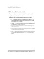
The assembler supports relative and absolute path names. When you specify an input or output file name as a parameter, use the following
guidelines for naming files:
• Include the drive letter and path string if the file is not in the current
directory.
• Enclose long file names in double quotation marks, for example,
"long file name".
• Append the appropriate file name extension to each file.
The assembler uses each file’s extension to determine what operations to
perform. Table 2-2 on page 2-19 lists the valid file extensions that the
assembler accepts.
The assembler handles file name extensions as follows:
• Files with an .ASM or no extension are treated as assembly source
files to be assembled.
• Files with an .H extension named in an #include command are
treated as header files to be preprocessed.
• Files with a .DAT extension named with an -I switch are treated as
data initialization files to be searched.
• File name typed in lower or uppercase defines the same file.
2-18 VisualDSP++ 2.0 Assembler & Preprocessor Manual for TigerSHARC DSPs
Assembler
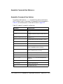
Table 2-2 summarizes file extension conventions that the assembler
follows.
Table 2-2. File Name Extension Conventions
Extension
File Description
.asm
Assembly source file.
"
Note that the assembler treats all files with unrecognized
extensions as assembly source files with an .asm extension.
.is
Preprocessed assembly source file.
.h
Header file.
.doj
Assembled object file in ELF/DWARF-2 format.
.dat
Data initialization file.
The assembler command-line switches are case-sensitive.
The following command line, for example:
easmts -TS001 - l p1List.lst -Dmax=100 -v -o bin\p1.doj p1.asm
runs the assembler with:
-TS001
— Assembles instructions unique to the ADSP-TS001 DSPs.
-l p1List —
-Dmax=100
-v
Directs the assembler to output the listing file.
— Defines the macro max as equal to 100.
— Displays verbose information on each phase of the assembly.
-o bin\p1.doj
— Specifies the name and directory for the assembled
object output.
p1.asm
— Names the assembly source to assemble.
VisualDSP++ 2.0 Assembler & Preprocessor Manual for TigerSHARC DSPs 2-19
Assembler Command-Line Reference
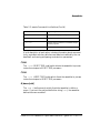
Assembler Command-Line Options
This section describes the easmts command-line options (switches) in
ASCII collation order. A summary of the assembler switches appears in
Table 2-3; a brief description of each switch starts on page 2-21.
Table 2-3. easmts Command-Line Switches
Switch Name
Usage Description
-TS001
Assembles instructions unique to ADSP-TS001 processors.
-TS101
Assembles instructions unique to ADSP-TS101 processors.
-D|dmacro[=definition]
Defines macro.
-g
Generates debug information (DWARF-2 format).
–h[elp]
Outputs a list of assembler switches.
–I|i directory
Searches directory for included files.
-l filename
Produces a listing file named <filename>. Nested
source files are not included in the listing.
-li filename
Produces a listing file named <filename>. Nested
source files are included in the listing.
-M
Makes dependencies only, does not assemble.
-MM
Makes dependencies and assembles.
-Mo filename
Specifies filename for the make dependencies
output file.
-Mt filename
Makes dependencies for the specified source file.
–o filename
Outputs named object file.
-pp
Runs preprocessor only.
2-20 VisualDSP++ 2.0 Assembler & Preprocessor Manual for TigerSHARC DSPs
Assembler
Table 2-3. easmts Command-Line Switches (Cont’d)
Switch Name
Usage Description
-sp
Assembles without preprocessing.
-v[erbose]
Displays information on each assembly phase.
–version
Displays version information for assembler and preprocessor programs.
-w
Removes all assembler-generated warnings.
A brief description of each option includes information about case-sensitivity, equivalent switches, switches overridden/contradicted by the one
described, and naming and spacing constraints on parameters.
-TS001
The -TS001 (ADSP-TS001 code) switch directs the assembler to process
instructions unique to ADSP-TS001 processors.
-TS101
The -TS101 (ADSP-TS101 code) switch directs the assembler to process
instructions unique to ADSP-TS101 processors.
-D|dmacro[=def]
The -D or -d (define macro) switch directs the assembler to define a
macro. If you omit the optional definition string ( =def), the assembler
defines the macro as value 1.
VisualDSP++ 2.0 Assembler & Preprocessor Manual for TigerSHARC DSPs 2-21
Assembler Command-Line Reference
Some examples of this switch are as follows:
–Dinput
// defines input as 1
–Dsamples=10
// defines samples as 10
–Dpoint=’Start’
// defines point as the string ‘Start’;
// note single quotes for the string
// as the assembler preferred style.
-g
The -g (generate debug information) switch directs the assembler to generate line number and symbol information in DWARF-2 binary format,
allowing you to debug the assembly source files.
-h[elp]
The -h or -help switch directs the assembler to output to standard out a
list of command-line switches with a syntax summary.
-I|i directory
The -i directory or -I directory (include directory) switch directs the
assembler to append the specified directory or a list of directories separated by semicolons (;) to the search path for included files. These files
are:
• header files (.h) included with the #include command
• data initialization files (.dat) specified with the .VAR directive
2-22 VisualDSP++ 2.0 Assembler & Preprocessor Manual for TigerSHARC DSPs
Assembler
The assembler passes this information to the preprocessor; the preprocessor searches for included files in the following order:
• current project ( .dpj) directory
•
…\TS\include
subdirectory of the VisualDSP++ installation direc-
tory
• specified directory (a list of directories). The order of the list defines
the order of multiple searches.
"
Current directory is your *.dpj project directory, not the
directory of the assembler program. Usage of full pathnames
for the -I switch on the command line (omitting the disk partition) is recommended. For example,
easmts -I “\bin\inlclude\buffer1.dat”
-l filename
The -l (listing) switch directs the assembler to generate the named listing
file. Each listing file shows the relationship between your source code and
instruction opcodes that the assembler produces. If you omit the filename, the assembler outputs an error message. For more information about
listing files, see “Reading a Listing File” on page 2-14.
-li filename
The -li (listing) switch directs the assembler to generate the named listing file with #include files used in the source printed in the listing file.
For more information about listing files, see “Reading a Listing File” on
page 2-14.
-M
The -M (generate make rule only) assembler switch directs the preprocessor to output a rule, which is suitable for the make utility, describing the
dependencies of the source file. After preprocessing, the assembler stops
VisualDSP++ 2.0 Assembler & Preprocessor Manual for TigerSHARC DSPs 2-23
Assembler Command-Line Reference
without assembling the source into an object file. The output, an assembly
make dependencies list, is written to stdout in the standard command-line format.
source_file: dependency_file.ext
where dependency_file.ext may be an assembly source file, a header file
included with the #include preprocessor command, or a data file.
When the -o filename option is used with -M, the assembler outputs the
make dependencies list to the named file.
-MM
The -MM (generate make rule and assemble) assembler switch directs the
preprocessor to output a rule, which is suitable for the make utility,
describing the dependencies of the source file. After preprocessing, the
assembly of the source into an object file proceeds normally. The output,
an assembly make dependencies list, is written to stdout in the standard
command-line format:
source_file.doj: dependency_file.ext
where dependency_file.ext may be an assembly source file, a header file
included with the #include preprocessor command, or a data file.
For example, the source vectAdd.asm includes the “MakeDepend.h” and
inits.dat files. When assembling with
easmts -MM vectAdd.asm
the assembler appends the .DOJ extension to the source file name for the
list of dependencies:
vectAdd.doj: MakeDepend.h
vectAdd.doj: inits.dat
When the -o filename option is used with -MM, the assembler outputs the
make dependencies list to stdout.
2-24 VisualDSP++ 2.0 Assembler & Preprocessor Manual for TigerSHARC DSPs
Assembler
-Mo filename
The -Mo (output make rule) assembler switch specifies the name of the
make dependencies file, which the assembler generates when you use the
-M or -MM switch. If the named file is not in the current directory, you
must provide the pathname in the double quotation marks (“”).
"
The -Mo
-o
option takes precedence over the
filename option.
filename
-Mt filename
The -Mt (output make rule for the named source) assembler switch specifies the name of the source file for which the assembler generates the make
rule when you use the -M or -MM switch. If the named file is not in the current directory, you must provide the pathname in the double quotation
marks ( “”).
-o [filename]
The -o (override) switch directs the assembler to use the specified filename argument for the object file. If you omit the switch or its argument,
the assembler uses the input file name for the output and appends a .DOJ
extension.
You also can use this switch to specify filename for the preprocessed
assembly file (.IS) — the only file that the preprocessor outputs when the
-pp switch is selected.
Some examples of this switch are as follows:
easmts -pp -o test1.is test.asm
// specify filename for the preprocessed file
easmts -o “C:\bin\prog3.doj” prog3.asm
// specify directory for the object file
VisualDSP++ 2.0 Assembler & Preprocessor Manual for TigerSHARC DSPs 2-25
Assembler Command-Line Reference
-pp
The -pp (proceed with preprocessing only) switch directs the assembler to
run the preprocessor, but stop without assembling the source into an
object file.
By default, the preprocessor generates an intermediate preprocessed
assembly file using the name of the source program and attaching an .IS
extension to it. When assembling with the -pp switch, the .IS file is the
final result of the assembly.
-sp
The -sp (skip preprocessing) switch directs the assembler to assemble the
source file into an object file without running the preprocessor. When the
assembly skips preprocessing entirely (the -sp switch), no preprocessed
assembly file ( .IS) is created.
-v[erbose]
The -v or -verbose (verbose) switch directs the assembler to display both
version and command-line information for each phase of assembly.
-version
The -version (display version) switch directs the assembler to display version information for the assembler and preprocessor programs.
-w
The -w (disable all warnings) switch directs the assembler not to display
warning messages generated during the assembly.
2-26 VisualDSP++ 2.0 Assembler & Preprocessor Manual for TigerSHARC DSPs
Assembler
Assembler Syntax Reference
When you develop a source program in assembly language, you include
preprocessor commands and assembler directives to control the program’s
processing and assembly. You must follow the assembler rules and conventions of syntax to define symbols (identifiers), expressions, and use
different numeric and comment formats.
Software developers who write assembly programs should be familiar with
the following topics:
• “Assembler Keywords & Symbols” on page 2-27
• “Assembler Expressions” on page 2-31
• “Assembler Operators” on page 2-32
• “Numeric Formats” on page 2-35
• “Comment Conventions” on page 2-38
• “Assembler Directives” on page 2-38
Assembler Keywords & Symbols
The assembler supports a set of predefined keywords that includes register
and bitfield names, assembly instructions, and assembler directives.
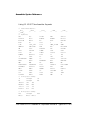
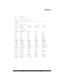
Listing 2-2 lists the assembler keywords. Although the keywords in this
listing appear in uppercase, the keywords are case insensitive in the assembler’s syntax. For example, the assembler does not differentiate between
“if” and “IF”.
VisualDSP++ 2.0 Assembler & Preprocessor Manual for TigerSHARC DSPs 2-27
Assembler Syntax Reference
Listing 2-2. ADSP-TSxxx Assembler Keywords
// Predefined Macros:
__ADI__
__DATE__
__TIME__
// Keywords:
ABS
ASHIFTR
BITFIFO
BTGL
CJMP
COMPACT
DO
EXTD
FILE
GLOBAL
JC
LEFTMARGIN
MANT
NOT
PAGELENGTH
PREVIOUS
ROTL
SCALB
SF1
TYPEVAR
ACS
BCLR
BKFPT
BY
CJMP_CALL
COPYSIGN
ELSE
EXTERN
FIX
GETBITS
JUMP
LOGB
MASK
NOP
PAGEWIDTH
PUTBITS
ROTR
SDAB
SNGL
VMIN
__FILE__
__LINE__
__STDC__
ALIGN
BFOINC
BR
CALL
CLIP
DAB
EMUTRAP
FCOMP
FLOAT
IDLE
KC
LP
MAXMERGE
NP
PASS
RESET
ROUND
SE
SIZE
VMAX
AND
BFOTMP
BSET
C
CODE_ALIGN
DEC
EXP
FEXT
FTEST0
IF
LD0
LSHIFT
MIN
ONES
PERMUTE
RDS
RECIPS
SECTION
SUM
XOR
ASHIFT
BITEST
BTBINV
CB
COMP
DESPREAD
EXPAND
FDEP
FTEST1
INC
LD1
LSHIFTR
NEWPAGE
OR
PRECISION
ROT
RSQRTS
SF0
TMAX
ZF
// JK Register Group:
J0
through
J31
K0
through
K31
JB0 JB1
JB2
JB3
KB0 KB1
KB2
KB3
JL0 JL1
JL2
JL3
KL0 KL1
KL2
KL3
// RF Register Group:
FR0
through
FR31
MR3:0
MR3:2 MR1:0
2-28 VisualDSP++ 2.0 Assembler & Preprocessor Manual for TigerSHARC DSPs
Assembler
R0
XSTAT
through
R31
YSTAT XYSTAT
// Accelerator Register Group:
TR0 TR1
TR2
TR3
TR4
TR5
THR0THR1
TR6
// EP Register Group:
BMAX
BMAXC
FLGPIN
SDRCON
SYSCON
SYSCONCL
SYSTAT
SYSTATCL
FLGPINCL
SYSCONST
FLGPINST
SYSCTL
// Misc. Register Group:
AUTODMA0 AUTODMA1
DBGE
DC6
DC7
DC8
DC11
DC12
DC13
DCD2
DCD3
DCNT
DCS0
DCS1
DCS2
DSTATC
ILATH
ILATL
IVBUSLK
IVDBG
IVHW
IVDMA2
IVDMA3
IVDMA4
IVDMA7
IVDMA8
IVDMA9
IVDMA12
IVDMA13
IVIRQ0
IVIRQ3
IVLINK0
IVLINK1
IVSW
IVTIMER0HP
IVTIMER0LP
LBUFRX0
LBUFRX1
LBUFRX2
LBUFTX1
LBUFTX2
LBUFTX3
LCTL0
LCTL1
LCTL2
LSTAT1
LSTAT2
LSTAT3
LSTATC2
LSTATC3
RETI
RTI
PMASKL
PMASKH
SQCTLST
SQCTLCL
SQSTAT
TIMER0H
TIMER1H
TMRIN0L
TMRIN1H
VIRPT
DC4
DC9
DCD0
DCNTCL
DCS3
IMASKH
IVDMA0
IVDMA5
IVDMA10
IVIRQ1
IVLINK2
IVTIMER1HP
LBUFRX3
LC0
LCTL3
LSTATC0
RETIB
SFREG
TIMER0L
TMRIN0H
DC5
DC10
DCD1
DCNTST
DSTAT
IMASKL
IVDMA1
IVDMA6
IVDMA11
IVIRQ2
IVLINK3
IVTIMER1LP
LBUFTX0
LC1
LSTAT0
LSTATC1
RETS
SQCTL
TIMER1L
TMRIN1L
TR7
TR8
TR9
VisualDSP++ 2.0 Assembler & Preprocessor Manual for TigerSHARC DSPs 2-29
Assembler Syntax Reference
You extend this set of keywords with symbols that declare sections, variables, constants, and address labels. When defining symbols in assembly
source code, follow these conventions:
• Define symbols that are unique within the file in which they are
declared.
If you use a symbol in more than one file, use the .GLOBAL directive
to export the symbol from the file in which it is defined. Then use
the .EXTERN directive to import the symbol into other files.
• Begin symbols with alphabetic characters.
Symbols can use the alphabetic characters (A—Z and a—z), digits (0—
and special characters $ and _ (dollar sign and underscore).
9),
Symbols are case-sensitive, so input_addr and INPUT_ADDR define
unique variables.
‘_’ as the first character of a symbol is considered reserved by the
assembler.
• Do not use a reserved keyword to define a symbol.
The ADSP-TSxxx assembler’s reserved keywords are shown in
Listing 2-2.
• Match source and LDF sections’ symbols.
Ensure that .SECTIONs’ name symbols do not conflict with the
linker’s keywords in the Linker Description File (.LDF). The linker
uses sections’ name symbols to place code and data in DSP memory.
For more details, see the VisualDSP++ 2.0 Linker & Utilities Manual for TigerSHARC DSPs.
Ensure that .SECTIONs’ name symbols do not begin with the ‘.rela.’
string reserved by the assembler to form relocatable sections.
• Use a colon (:) to terminate address label symbols.
2-30 VisualDSP++ 2.0 Assembler & Preprocessor Manual for TigerSHARC DSPs
Assembler
Address label symbols may appear at the beginning of an instruction line
or stand alone on the preceding line.
The following disassociated lines of code demonstrate some symbol usage:
.VAR xoperand;
// xoperand is a data variable
.VAR input_array[10];
// input_array is a data buffer
sub_routine_1:
// sub_routine_1 is a label
.SECTION kernel;
// kernel is a user-defined section; corresponds
// to the LDF input section
Assembler Expressions
The assembler can evaluate simple expressions in source code. The assembler supports two types of expressions:
• Constant expressions
A constant expression is acceptable wherever a numeric value is
expected in an assembly instruction or in a preprocessor command.
Constant expressions contain an arithmetic or logical operation on
two or more numeric constants:
2.9e-5 + 1.29
(128 - 48) / 3
0x55 & 0x0f
-1.6r - .8r
For information about fraction type support, refer to “Numeric Formats” on page 2-35.
VisualDSP++ 2.0 Assembler & Preprocessor Manual for TigerSHARC DSPs 2-31
Assembler Syntax Reference
• Address expressions
Address expressions contain a symbol + or - and integer constant:
data - 8
data_buffer + 15
strtup + 2
Symbols in this type of expression are data variables, data buffers,
and program labels. Adding or subtracting an integer from a symbol specifies an offset from the address the symbol represents.
Assembler Operators
Table 2-4 lists the assembler’s numeric and bitwise operators used in constant expressions and address expressions. These operators are listed in the
order they are processed while the assembler evaluates your expressions.
Note that assembler limits operators in address expressions to addition
and subtraction.
Table 2-4. Operator Precedence Char t
Operator
Usage Description
(expression)
expression in parenthesis evaluates first.
~
Ones complement.
-
Unary minus.
*
Multiply.
/
Divide.
%
Modulus.
+
Addition.
-
Subtraction.
2-32 VisualDSP++ 2.0 Assembler & Preprocessor Manual for TigerSHARC DSPs
Assembler
Table 2-4. Operator Precedence Chart (Cont’d)
Operator
Usage Description
<<
Shift left.
>>
Shift right.
<
Less than.
<=
Less than or equal.
>
Greater than.
>=
Greater than or equal.
==
Equal.
!=
Not equal.
&
Bitwise AND.
|
Bitwise inclusive OR.
^
Bitwise exclusive OR.
&&
Logical AND.
||
Logical OR.
The assembler also supports special “address of”, “length of”, and “page
of” operators.
VisualDSP++ 2.0 Assembler & Preprocessor Manual for TigerSHARC DSPs 2-33
Assembler Syntax Reference
Table 2-5 lists and describes these operators used in constant and address
expressions.
Table 2-5. Special Assembler Operators
Operator
Usage Description
ADDRESS(symbol)
Least significant 16 address bits of symbol.
symbol
Address pointer to symbol.
LENGTH(symbol)
Length of symbol in words.
The “address of” and “length of” operators can be used with external symbols — apply these special operators to symbols that are defined in other
sections as .GLOBAL symbols.
The following example demonstrates how the assembler operators are used
to load JL3 (length) and J3 (index) registers when setting up circular
buffers:
.SECTION data1;
.VAR real_data[n];
…
// data segment
// n = number of input samples
.SECTION program;
// code segment
// Load the base address of the circular buffer:
JB3 = real_data;;
// Load the index:
J3=real_data;;
// Load the circular buffer length:
JL3 = LENGTH(real_data);;
// Set loop counter 0 with buffer length:
LC0 = JL3;;
start:
XR0 = CB [J3 += 1];;
// read data from circular buffer
if NLC0E, jump start;;
2-34 VisualDSP++ 2.0 Assembler & Preprocessor Manual for TigerSHARC DSPs
Assembler
This code fragment initializes JB3 and JL3 to the base address and length,
respectively, of the circular buffer real_data. The buffer length value
contained in JL3 determines when addressing wraps around the top of the
buffer. For further information on circular buffers, refer to your DSP
Hardware Reference Manual.
Numeric Formats
The assembler supports binary, decimal, and hexadecimal numeric formats (bases) within expressions and assembly instructions.
Table 2-6 describes the conventions of notation the assembler uses to distinguish between numeric formats.
Table 2-6. Numeric Formats
Convention
Description
0xnumber
A “0x” prefix indicates a hexadecimal number.
B#number
b#number
A “B#” or “b#” prefix indicates a binary number.
number
No prefix indicates a decimal number.
numberr
An “r” suffix indicates a fractional number.
Note that if any operand in an expression is a floating-point value, the
assembler stores the value of the expression in floating-point format.
Fractional Type Support
Fractional (fract) constants are specially marked floating-point constants
to be represented in fixed-point. A fract constant uses the floating-point
representation with a trailing "r", where "r" stands for "fract". The legal
VisualDSP++ 2.0 Assembler & Preprocessor Manual for TigerSHARC DSPs 2-35
Assembler Syntax Reference
range is [-1.0 … 1.0). Fracts are represented as signed values, which
means the values must be greater than or equal -1 and less than 1.
Example:
.VAR myFracts[4] = 0.5r, -0.5e-4r, -0.25e-3r, 0.875r;
/* constants are examples of legal fracts */
.VAR OutOfRangeFract = 1.5r;
/* [Error E37] …Fract constant '1.5r' is out of range. Fract
constants must be greater than or equal to -1 and less than 1.
*/
1.15 Fracts
TigerSHARC supported fracts use 1.15 format, meaning a sign bit and
"15 bits of fraction". This is -1 to +1-2**15. For example, 1.15 maps the
constant 0.5r to 2**14.
The conversion formula used for TigerSHARC DSP to convert from the
floating-point to fixed-point uses a scale factor of 15:
fractValue = (short) (doubleValue * (1 << 15))
Example:
.VAR myFract = .5r;
// Fract output for 0.5r is 0x4000
// sign bit + 15 bits
// 0100 0000 0000 0000
//
4
0
0
0 = 0x4000 = .5r
.VAR myFract = -1.0r;
// Fract output for -1.0r is 0x8000
// sign bit + 15 bits
// 1000 0000 0000 0000
//
8
0
0
0 = 0x8000 = -1.0r
1.0r Special Case
1.0r is out of the range fract. Specify 0x7FFF for the closest approximation
of 1.0r within the 1.15 representation.
2-36 VisualDSP++ 2.0 Assembler & Preprocessor Manual for TigerSHARC DSPs
Assembler
Fractional Arithmetic
The assembler supports arithmetic operations on fractional constants. As
implemented, constant fract expressions are consistent with what is provided for other numeric types in the assembler. Doing fract constant
arithmetic is sometimes necessary when one receives constants and wants
to derive others from them.
The internal (intermediate) representation for expression evaluation is a
double floating-point value. Fract range checking is deferred until the
expression is evaluated.
#define some_val
0.875r
.SECTION data1;
.VAR localOne = some_val + 0.005r;
// Result .88r is within the legal range
.VAR xyz = 1.5r - .9r; // Result .6r is within the legal range
.VAR abc = 1.5r;
// Error: 1.5r out of range
Mixed Type Arithmetic
The assembler implementation currently supports arithmetic between
fracts, but not fracts and integers.
.VAR myFract = 1 - 0.5r;
[Error E8] …Assembler Error: Illegal mixing of types in
expression.
VisualDSP++ 2.0 Assembler & Preprocessor Manual for TigerSHARC DSPs 2-37
Assembler Syntax Reference
Comment Conventions
The assembler supports C- and C++-style formats for inserting comments
into assembly sources. Note that the assembler does not allow nested
comments.
Table 2-7 lists and describes the easmts comment conventions.
Table 2-7. Comment Conventions
Convention
Description
/* comment */
A “/* */” string encloses a multiple-line comment.
// comment
A pair of slashes “//” begin a single-line comment.
Assembler Directives
Directives in an assembly source file control the assembly process. Unlike
instructions, directives do not produce opcodes during assembly. Use the
following general syntax for the assembler directives:
.directive [/qualifiers |arguments];
Each assembler directive starts with a period (.) and ends with a semicolon ( ;). Some directives take qualifiers and arguments. A directive’s
qualifier immediately follows the directive and is separated by a slash (/);
arguments follow qualifiers. Comments may follow the directive’s terminating semicolon. Assembler directives can be uppercase or lowercase.
2-38 VisualDSP++ 2.0 Assembler & Preprocessor Manual for TigerSHARC DSPs
Assembler
The ADSP-TSxxx assembler supports directives shown in Table 2-8. A
description of each directive appears in the following sections.
Table 2-8. Assembler Directives
Directive
Description
.ALIGN (see page 2-41)
Specifies a word alignment requirement for data.
.ALIGN_CODE (see page 2-44)
Specifies a word alignment requirement for code.
.EXTERN (see page 2-46)
Allows reference a global symbol.
.FILE (see page 2-47)
Overrides filename given on the command
line. Used by C/C++ compiler.
.GLOBAL (see page 2-47)
Changes a symbol’s scope from local to global.
.LEFTMARGIN (see page 2-49)
Defines the width of the left margin of a listing.
.LIST (see page 2-50)
Starts listing of source lines.
.LIST_DATFILE (see page 2-51)
Starts listing of data initialization files.
.LIST_DEFTAB (see page 2-52)
Sets the default tab width for listings.
.LIST_LOCTAB (see page 2-53)
Sets the local tab width for listings.
.LIST_WRAPDATA (see page 2-54)
Starts wrapping opcodes that don't fit listing column.
.NEWPAGE (see page 2-55)
Inserts a page break in a listing.
.NOLIST (see page 2-50)
Stops listing of source lines.
.NOLIST_DATFILE (see page 2-51)
Stops listing of data initialization files.
.NOLIST_WRAPDATA (see page 2-54)
Stops wrapping opcodes that don't fit listing column.
VisualDSP++ 2.0 Assembler & Preprocessor Manual for TigerSHARC DSPs 2-39
Assembler Syntax Reference
Table 2-8. Assembler Directives (Cont’d)
Directive
Description
.PAGELENGTH (see page 2-56)
Defines the length of a listing.
.PAGEWIDTH (see page 2-57)
Defines the width of a listing.
.PRECISION (see page 2-58)
Selects a floating-point precision.
.PREVIOUS (see page 2-59)
Reverts to a previously described .SECTION.
.ROUND (see page 2-60)
Selects floating-point rounding.
.SECTION (see page 2-62)
Marks the beginning of a section.
.SIZE (see page 2-64)
Calculates the size of a function.
.TYPE (see page 2-65)
Changes the default data type of a symbol. Used
by C compiler.
.VAR (see page 2-66)
Defines and initializes data objects.
2-40 VisualDSP++ 2.0 Assembler & Preprocessor Manual for TigerSHARC DSPs
Assembler
.ALIGN, Specify an Address Alignment
The .ALIGN directive forces the address alignment of a data item within
the .SECTION it is used. When aligning instructions, the .ALIGN_CODE
directive to be used instead. For information about .ALIGN_CODE, see
page 2-44.
The .ALIGN directive uses the following syntax:
.ALIGN expression;
where:
•
evaluates to an integer. The expression specifies the
word alignment requirement; its value must be a power of 2. When
aligning a data item or instruction, the assembler adjusts the address
of the current location counter to the next address so it can be evenly
divided by the value of expression, or aligned. The expression set
to 0 or 1 signifies no address alignment requirement.
expression
In the absence of the
directive, the default address align" ment
is set to 1, i.e. single-word alignment.
.ALIGN
Example:
.ALIGN 1;
/* no alignment requirement */
…
.SECTION data1;
ALIGN 2;
.VAR single;
location
/* aligns the data item on the word boundary, at the
with the address value that can be evenly divided by 2 */
.ALIGN 4;
.VAR samples1[100]=”data1.dat”;
/* aligns the first data item on the double-word
boundary,
be evenly
at the location with the address value that can
divided by 4; advances other data items consequently */
VisualDSP++ 2.0 Assembler & Preprocessor Manual for TigerSHARC DSPs 2-41
Assembler Syntax Reference
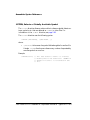
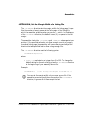
INPUT_SECTION_ALIGN(), Specify an Input Section Alignment in LDF
The INPUT_SECTION_ALIGN(#number) instruction is used by the linker in
the Linker Description File to align the input sections (instructions or
data) specified within an output section.
The TigerSHARC processors can execute up to four instructions per cycle
from a single memory block, due to the 128-bit wide access per cycle.
Quad-word accesses may be used to supply four aligned words to one
compute block or two aligned words to each compute block. The assembler does not quad align code or data sections automatically. To align a
section, you have to use the .ALIGN directive for assembly programs.
The INPUT_SECTION_ALIGN() operator uses the following syntax:
INPUT_SECTION_ALIGN(address_boundary_expession)
INPUT_SECTIONS(filename(input section name)
aligns the input section to the next word
boundary. The expression must be a power of 2. Legal values for this
expression depend on the word size of the segment that receive the output
section being aligned.
address_boundary_expession
The following example shows how to align input sections using the Linker
Description File:
SECTIONS
{
code
{
INPUT_SECTION_ALIGN(4)
INPUT_SECTIONS( a.doj(program))
INPUT_SECTIONS( b.doj(program))
INPUT_SECTIONS( c.doj(program))
INPUT_SECTION_ALIGN(1)
// end of alignment directive for input sections
2-42 VisualDSP++ 2.0 Assembler & Preprocessor Manual for TigerSHARC DSPs
Assembler
// The following sections will not be aligned
INPUT_SECTIONS( d.doj(program))
INPUT_SECTIONS( e.doj(program))
} >M2Code
}
Here the input sections specified after INPUT_SECTION_ALIGN(4) but
before the INPUT_SECTION_ALIGN(1) instructions are aligned. However,
the input sections from d.doj and e.doj are not aligned as the
INPUT_SECTION_ALIGN(1) instruction indicates the end of the alignment
directive.
The INPUT_SECTION_ALIGN() operator is valid only within the scope of an
output section the Linker Description File. This command gives you the
flexibility to align the input sections as needed.
VisualDSP++ 2.0 Assembler & Preprocessor Manual for TigerSHARC DSPs 2-43
Assembler Syntax Reference
.ALIGN_CODE, Specify an Address Alignment
The .ALIGN directive forces the address alignment of an instruction or
data item within the .SECTION it is used. It is similar to the .ALIGN directive, but whereas .ALIGN causes the code to be padded with 0’s,
.ALIGN_CODE pads with NOP’s. The .ALIGN_CODE directive is used when
aligning instructions.
The .ALIGN_CODE directive uses the following syntax:
.ALIGN_CODE expression;
where:
•
evaluates to an integer. The expression specifies the
byte alignment requirement; its value must be a power of 2. When
aligning a data item or instruction, the assembler adjusts the address
of the current location counter to the next address so it can be evenly
divided by the value of expression, or aligned. The expression set
to 0 or 1 signifies no address alignment requirement.
expression
the absence of the
or
" Indefault
address alignment is set to 1.
.ALIGN_CODE
.ALIGN
directive, the
Example:
.ALIGN_CODE 0;
…
.ALIGN_CODE 1;
…
.SECTION program;
.ALIGN_CODE 8;
_f1:
.LN1:
J8 = [j31 + 0x40];;
/* no alignment requirement */
/* no alignment requirement */
/* aligned code section on the
/ word boundary at the location
/ with an address boundary that
/ is divisible by 8*/
2-44 VisualDSP++ 2.0 Assembler & Preprocessor Manual for TigerSHARC DSPs
Assembler
.ALIGN_CODE 32;
J8 = [j31 + 0x4000];r3=100;; /* aligned code section on the
/ word boundary at the location
/ with an address boundary that
/ is divisible by 32*/
.ALIGN_CODE 16;
r3=100;;
.ALIGN_CODE 8;
cjmp (ABS);;
/* aligned code section on the
/ word boundary at the location
/ with an address boundary that
/ is divisible by 16*/
/* aligned code section on the
/ word boundary at the location
/ with an address boundary that
/ is divisible by 8*/
J8 = [j31 + 0x40];;
J8 = [j31 + 0x40];r3=100;;
VisualDSP++ 2.0 Assembler & Preprocessor Manual for TigerSHARC DSPs 2-45
Assembler Syntax Reference
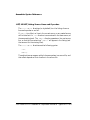
.EXTERN, Refer to a Globally Available Symbol
The .EXTERN directive allows a code module to reference global data structures, symbols, etc. that are declared as .GLOBAL in other files. For
information on the .GLOBAL directive, see page 2-48.
The .EXTERN directive uses the following syntax:
.EXTERN symbolName1[, symbolName2, …];
where:
•
is the name of a symbol defined as global in another file.
A single .EXTERN directive can reference any number of separated by
commas symbols on one line.
symbolName
Example:
.EXTERN coeffs; //
//
//
//
This code declares “coeffs” as external,
meaning that it was declared as .GLOBAL in
another file and it is referenced in this
file.
2-46 VisualDSP++ 2.0 Assembler & Preprocessor Manual for TigerSHARC DSPs
Assembler
.FILE Override the Name of an Object File
The .FILE directive overrides the name of an object file specified with the
command-line switch. This directive may appear in the C
compiler-generated assembly source file (.S). The .FILE directive is used
to ensure that the debugger has the correct file name for a symbol table.
This directive is added in connection with overlay linking to enable overriding of the filename given on the command line.
-o filename
This directive uses the following syntax:
.FILE “filename.ext”;
where:
•
is the name the assembler applies to the object file. The
argument is enclosed in double quotes.
filename
Example:
.FILE “vect.c”;
.SECTION data1;
…
…
// the argument may be a *.c file
VisualDSP++ 2.0 Assembler & Preprocessor Manual for TigerSHARC DSPs 2-47
Assembler Syntax Reference
.GLOBAL Make a Symbol Globally Available
The .GLOBAL directive changes the scope of a symbol from local to global,
making the symbol available for reference in object files that are linked
with the current one.
By default, a symbol is valid only in the file in which it is declared. Local
symbols in different files can have the same name, and the assembler considers them to be independent entities. Global symbols are recognizable in
other files and refer to the same address and value. You change the default
scope of a symbol with the .GLOBAL directive. Once the symbol is declared
global, other files may refer to it with .EXTERN. For more information on
the .EXTERN directive, see page 2-46.
The .GLOBAL directive uses the following syntax:
.GLOBAL symbolName1[, symbolName2,…];
where:
•
is the name of a global symbol. A single .GLOBAL directive may define the global scope of any number of symbols, separated by commas, on one line.
symbolName
Example:
.VAR coeffs[10];
.VAR taps=100;
.GLOBAL coeffs, taps;
//
//
//
//
declares a buffer
declares a variable
makes the buffer and the variable
visible in other file s
2-48 VisualDSP++ 2.0 Assembler & Preprocessor Manual for TigerSHARC DSPs
Assembler
.LEFTMARGIN, Set the Margin Width of a Listing File
The .LEFTMARGIN directive sets the margin width of a listing page. It specifies the number of empty spaces at the left margin of the listing file,
which the assembler produces when you use the -l switch. In the absence
of the .LEFTMARGIN directive, the default is zero (0), no spaces in the left
margin.
The assembler checks the .LEFTMARGIN and .PAGEWIDTH values against one
another. If the specified values do not allow enough room for a properly
formatted listing page, the assembler will issue a warning and adjust the
directive that was specified last to allow a long enough line.
The .LEFTMARGIN directive uses the following syntax:
.LEFTMARGIN expression;
where:
•
evaluates to an integer from 0 to 100. To change the
default setting for the entire listing, place the .LEFTMARGIN directive
at the beginning of your assembly source file.
expression
Example:
.LEFTMARGIN 9;
/* the listing line begins at column 10. */
can set the margin width only once per source file. If the
" You
assembler encounters multiple occurrences of the
.LEFTMARGIN
directive, it ignores all of them except the last.
VisualDSP++ 2.0 Assembler & Preprocessor Manual for TigerSHARC DSPs 2-49
Assembler Syntax Reference
.LIST/.NOLIST, Listing Source Lines and Opcodes
The .LIST/.NOLIST directives (on by default) turn the listing of source
lines and opcodes on and off.
If .NOLIST is in effect, no lines in the current source, or any nested source,
will be listed until a .LIST directive is encountered in the same source, at
the same nesting level. The .NOLIST directive operates on the next source
line, so that the line containing " .NOLIST" will appear in the listing (and
thus account for the missing lines).
The .LIST/.NOLIST directives use the following syntax:
.LIST;
.NOLIST;
These directives can appear multiple times anywhere in a source file, and
their effect depends on their location in the source file.
2-50 VisualDSP++ 2.0 Assembler & Preprocessor Manual for TigerSHARC DSPs
Assembler
.LIST_DATFILE/.NOLIST_DATFILE, Listing Data Initialization Files
The .LIST_DATFILE/.NOLIST_DATFILE directives (off by default) turn the
listing of data initialization files on or off. Nested source files inherit the
current setting of this directive pair, but a change to the setting made in a
nested source file will not affect the parent source file.
The .LIST_DATFILE/.NOLIST_DATFILE directives use the following syntax:
.LIST_DATFILE;
.NOLIST_DATFILE;
These directives can appear multiple times anywhere in a source file, and
their effect depends on their location in the source file. They are used in
assembly source files, and not in data initialization files.
VisualDSP++ 2.0 Assembler & Preprocessor Manual for TigerSHARC DSPs 2-51
Assembler Syntax Reference
.LIST_DEFTAB, Set the Default Tab Width for Listings
Tab characters in source files are expanded to blanks in listing files under
the control two internal assembler parameters that set the tab expansion
width. The default tab width is normally in control, but it can be overridden if the local tab width is explicitly set with a directive.
The .LIST_DEFTAB directive sets the default tab width, and the
.LIST_LOCTAB directive sets the local tab width (see “.LIST_LOCTAB,
Set the Local Tab Width for Listings” on page 2-53).
Both the default tab width and the local tab width can be changed any
number of times via the .LIST_DEFTAB and .LIST_LOCTAB directives. The
default tab width is inherited by nested source files, but the local tab
width only affects the current source file.
The .LIST_DEFTAB directive uses the following syntax:
.LIST_DEFTAB expression;
where:
•
evaluates to an integer greater than or equal to 0. A
value of 0 sets the default tab width to the default tab width.
expression
In the absence of a .LIST_DEFTAB directive, the default tab width defaults
to 4.
Example:
// Tabs here are expanded to the default of 4 columns
.LIST_DEFTAB 8;
// Tabs here are expanded to 8 columns
.LIST_LOCTAB 2;
// Tabs here are expanded to 2 columns
// But tabs in "include_1.h" will be expanded to 8 columns
#include "include_1.h"
.LIST_DEFTAB 4;
// Tabs here are still expanded to 2 columns
// But tabs in "include_2.h" will be expanded to 4 columns
#include "include_2.h"
2-52 VisualDSP++ 2.0 Assembler & Preprocessor Manual for TigerSHARC DSPs
Assembler
.LIST_LOCTAB, Set the Local Tab Width for Listings
Tab characters in source files are expanded to blanks in listing files under
the control of two internal assembler parameters that set the tab expansion
width. The default tab width is normally in control, but it can be overridden if the local tab width is explicitly set with a directive.
The .LIST_LOCTAB directive sets the local tab width, and the .LIST_DEFTAB
directive sets the default tab width (see “.LIST_DEFTAB, Set the Default
Tab Width for Listings” on page 2-52).
Both the default tab width and the local tab width can be changed any
number of times via the .LIST_DEFTAB and .LIST_LOCTAB directives. The
default tab width is inherited by nested source files, but the local tab
width only affects the current source file.
The .LIST_LOCTAB directive uses the following syntax:
.LIST_LOCTAB expression;
where:
•
evaluates to an integer greater than or equal to 0.
A value of 0 sets the local tab width to the current setting of the
default tab width.
expression
In the absence of a .LIST_LOCTAB directive, the local tab width defaults to
the current setting for the default tab width.
Example: See the .LIST_DEFTAB example on page 2-52.
VisualDSP++ 2.0 Assembler & Preprocessor Manual for TigerSHARC DSPs 2-53
Assembler Syntax Reference
.LIST_WRAPDATA/.NOLIST_WRAPDATA
The .LIST_WRAPDATA/.NOLIST_WRAPDATA directives control the listing of
opcodes that are too big to fit in the opcode column. These directives are
off by default.
This directive pair actually applies to any opcode that won't fit, but in
practice such a value will almost always be data (alignment directives can
also result in large opcodes).
• If .LIST_WRAPDATA is in effect, the opcode value is wrapped so that
it fits in the opcode column (resulting in multiple listing lines).
• If.NOLIST_WRAPDATA is in effect, the printout has only as much as
fits in the opcode column. Nested source files inherit the current
setting of this directive pair, but a change to the setting made in a
nested source file will not affect the parent source file.
The .LIST_WRAPDATA/.NOLIST_WRAPDATA directives use the following
syntax:
.LIST_WRAPDATA;
.NOLIST_WRAPDATA;
These directives can appear multiple times anywhere in a source file, and
their effect depends on their location in the source file.
2-54 VisualDSP++ 2.0 Assembler & Preprocessor Manual for TigerSHARC DSPs
Assembler
.NEWPAGE, Insert a Page Break in a Listing File
The .NEWPAGE directive inserts a page break in the printed listing file,
which the assembler produces when you use the -l switch. The assembler
inserts a page break at the location of the .NEWPAGE directive.
The .NEWPAGE directive uses the following syntax:
.NEWPAGE;
This directive may appear anywhere in your source file. In the absence of
the .NEWPAGE directive, a page is ejected after listing 66 lines.
VisualDSP++ 2.0 Assembler & Preprocessor Manual for TigerSHARC DSPs 2-55
Assembler Syntax Reference
.PAGELENGTH, Set the Page Length of a Listing File
The .PAGELENGTH directive controls the page length of the listing file,
which the assembler produces when you use the -l switch.
The .PAGELENGTH directive uses the following syntax:
.PAGELENGTH expression;
where:
•
evaluates to an integer from 0 to 66. Default is 0.
It specifies the number of text lines per printed page. In its absence,
the default setting is 0, which means the listing does not have any
page breaks.
expression
To format the entire listing, place the .PAGELENGTH directive at the beginning of your assembly source file. If a page length value greater than 0 is
too small to allow a properly formatted listing page, the assembler will
issue a warning and use its internal minimum page length (approximately
10 lines).
Example:
.PAGELENGTH 50;
// starts a new page
// after printing 50 lines
can set the page length only once per source file. If the
" You
assembler encounters multiple occurrences of the
.PAGELENGTH
directive, it ignores all of them except the last.
2-56 VisualDSP++ 2.0 Assembler & Preprocessor Manual for TigerSHARC DSPs
Assembler
.PAGEWIDTH, Set the Page Width of a Listing File
The .PAGEWIDTH directive sets the page width of the listing file, which the
assembler produces when you use the -l switch.
The .PAGEWIDTH directive uses the following syntax:
.PAGEWIDTH expression;
where:
•
expression
evaluates to an integer from 0 to 72. Default is 0.
The zero default page width means that source lines will not be wrapped
no matter how long they are. A page width greater than 0 means that
source file lines that are too long to fit in the assembly source column of
the listing will be wrapped into two or more listing lines. There is no maximum allowed page width.
The assembler checks the .LEFTMARGIN and .PAGEWIDTH values against one
another. If the specified values do not allow enough room for a properly
formatted listing page, the assembler will issue a warning and adjust the
directive that was specified last to allow a long enough line.
Example:
.PAGEWIDTH 36; // starts a new line after 36
// characters are printed on one line
can set the page width only once per source file. If the
" You
assembler encounters multiple occurrences of the
.PAGEWIDTH
directive, it ignores all of them except the last.
VisualDSP++ 2.0 Assembler & Preprocessor Manual for TigerSHARC DSPs 2-57
Assembler Syntax Reference
.PRECISION, Select Floating-Point Precision
The .PRECISION directive controls how the assembler interprets floating-point numeric values in constant declarations and variable
initializations. Note that you configure the floating-point precision of the
target DSP system by setting up control registers with instructions that
specific to the processor core.
Use one of the following options:
.PRECISION [=] 32;
.PRECISION [=] 40;
where:
• The precision of 32 or 40 specifies the number of significant bits for
floating-point data. The equal sign (=) following the .PRECISION
keyword is optional.
Example:
.PRECISION=32; /* Selects standard IEEE 32-bit
single-precision format; this is the default
setting */
.PRECISION 40; /* Selects standard IEEE 40-bit format with
extended mantissa */
applies only to floating-point data. Precision of
" fixed-point data
is determined by the number of digits speci.PRECISION
fied.
2-58 VisualDSP++ 2.0 Assembler & Preprocessor Manual for TigerSHARC DSPs
Assembler
.PREVIOUS, Revert to the Previously Defined Section
The .PREVIOUS directive instructs the assembler to set the current section
in processor’s memory to the section that has been described directly
before the current one.
This directive uses the following syntax:
.PREVIOUS;
Example:
.SECTION sec_one;
…
// data & instructions
.SECTION sec_two;
…
// data
.PREVIOUS;
…
// data & instructions
directs the assembler to revert back to sec_one and has the same effect as:
.SECTION sec_one;
…
// data & instructions
.SECTION sec_two;
…
// data
.SECTION sec_one;
…
// data & instructions
VisualDSP++ 2.0 Assembler & Preprocessor Manual for TigerSHARC DSPs 2-59
Assembler Syntax Reference
.ROUND, Select Floating-Point Rounding
The .ROUND_ directive controls how the assembler interprets literal floating-point numeric data after .PRECISION is defined. The .PRECISION
directive determines the number of bits to be truncated to match the
number of significant bits.
The .ROUND_ directive determines how the assembler handles floating-point values in constant declarations and variable initializations. You
configure floating-point rounding modes of the DSP system by setting up
control registers with the instructions specific to the target processor. The
.ROUND_ directive uses the following syntax:
.ROUND_mode;
where:
• The mode string specifies the rounding scheme used to fit a value in
the destination format. Use one of the following IEEE standard
modes:
.ROUND_NEAREST;
.ROUND_PLUS;
.ROUND_MINUS;
.ROUND_ZERO;
In the following examples, the numbers with four decimal places are
reduced to three decimal places and are rounded accordingly the rounding
mode:
.ROUND_NEAREST;
/* Selects Round-to-Nearest scheme; this is the default
setting.
A 5 is added to the digit that follows the third
decimal digit (the least significant bit - LSB). The
result is truncated after the third decimal digit (LSB).
1.2581 rounds to 1.258
8.5996 rounds to 8.600
2-60 VisualDSP++ 2.0 Assembler & Preprocessor Manual for TigerSHARC DSPs
Assembler
-5.3298 rounds to -5.329
-6.4974 rounds to -6.496
*/
.ROUND_ZERO;
/* Selects Round-to-Zero. The closer to zero value is
taken.
The number is truncated after the third decimal digit
(LSB).
1.2581 rounds to 1.258
8.5996 rounds to 8.599
-5.3298 rounds to -5.329
-6.4974 rounds to -6.497
*/
.ROUND_PLUS;
/* Selects Round-to-Positive Infinity. The number rounds
to the next larger.
For positive numbers, a 1 is added to the third decimal
digit (the least significant bit). Then the result is
truncated after the LSB.
For negative numbers, the mantissa is truncated after
the third decimal digit (LSB).
1.2581 rounds to 1.259
8.5996 rounds to 8.600
-5.3298 rounds to -5.329
-6.4974 rounds to -6.497
*/
.ROUND_MINUS;
/* Selects Round-to-Negative Infinity. The value
rounds to the next smaller.
For negative numbers, a 1 is subtracted from the
third decimal digit (the least significant bit).
Then the result is truncated after the LSB.
For positive numbers, the mantissa is truncated
after the third decimal digit (LSB).
1.2581 rounds to 1.258
8.5996 rounds to 8.599
-5.3298 rounds to -5.330
-6.4974 rounds to -6.498
*/
VisualDSP++ 2.0 Assembler & Preprocessor Manual for TigerSHARC DSPs 2-61
Assembler Syntax Reference
.SECTION, Declare a Memory Section
The .SECTION directive marks the beginning of a logical section mirroring
an array of contiguous locations in unified memory of TigerSHARC system. Statements between .SECTION and the following .SECTION directive
or the end-of-file comprise the contents of the section.
This directive uses the following syntax:
.SECTION sectionName [sectionType];
where:
• The section name symbol, sectionName, is not limited in length and
is case-sensitive. Section names must match the corresponding
input section names used by the Linker Description File to place the
section. You can use the default LDF included in the .\Ts\ldf subdirectory of the VisualDSP++ installation directory, or you can
write your own LDF.
The assembler generates relocatable sections for the linker to fill in
the addresses of symbols at link time. The TigerSHARC assembler
implicitly pre-fix the name of the section with the ‘.rela.’ string to
form a relocatable section. For example, for the sections named
rela.seg_data and rela.seg_code, the relocation section are
.rela.rela.seg_data and .rela.rela.seg_code, respectively. To
avoid such an ambiguity, ensure that your sections’ names do not
begin with ‘.rela.’.
• The sectionType is an optional ELF symbol type STT_*. Valid sectionTypes are described in the ELF.h header file, which is available
from the third parties.
2-62 VisualDSP++ 2.0 Assembler & Preprocessor Manual for TigerSHARC DSPs
Assembler
Example:
/* Declared below data and program sections correspond to the
default LDF’s input sections. */
.SECTION data1;
…
// memory section to store data
.SECTION program;
…
// memory section to store code
VisualDSP++ 2.0 Assembler & Preprocessor Manual for TigerSHARC DSPs 2-63
Assembler Syntax Reference
.SIZE Calculate the Size of a Function
The .SIZE directive directs the assembler to mark the boundaries of a
function, thus allowing for size calculation. The . SIZE directive may
appear in the compiler-generated assembly source code as the statement
following the last instruction of a function.
This directive uses the following syntax:
.SIZE(functionSymbol, .-functionLabel);
where:
•
functionSymbol
•
.-functionLabel
is the function identifier.
is the assembler generated label. Note that functionLabel’s preceding character ( .-) is allowed in this syntax only.
The assembler creates two relocations for each .SIZE directive — for the
beginning and closing labels. The linker resolves the .SIZE directive at
link time; this provides correct size calculations of assembly functions that
may change their size at link time.
Example:
start:
NOP;
NOP;
NOP;
.SIZE(start, .-start);
2-64 VisualDSP++ 2.0 Assembler & Preprocessor Manual for TigerSHARC DSPs
Assembler
.TYPE, Change Default Symbol Type
The .TYPE directive enables the compiler to change the default symbol
type of an object. This directive may appear in the compiler-generated
assembly source file (.S).
This directive uses the following syntax:
.TYPE symbolName, symbolType;
where:
is the name of the object, which symbol type the compiler has changed.
•
symbolName
•
symbolType
is the ELF symbol type STT_* . The valid ELF symbol
types are listed in the ELF.h header file. By default, a label in a code
section has the STT_FUNC symbol type and a label in a data section
has the STT_OBJECT symbol type.
VisualDSP++ 2.0 Assembler & Preprocessor Manual for TigerSHARC DSPs 2-65
Assembler Syntax Reference
.VAR, Declare a Data Variable or Buffer
The .VAR directive declares and optionally initializes variables and data
buffers. A variable uses a single memory location, and a data buffer uses an
array of memory locations.
When declaring or initializing variables, be aware of the following:
• A .VAR directive is valid only if it appears within a section. The
assembler associates the variable with the memory type of the section in which the .VAR appears.
• A single .VAR directive can declare any number of variables or buffers, separated by commas, on one line.
• Referring to variables and buffers in code before declaring them,
leads to syntax errors.
• The number of initial values may not exceed the number of variables
or buffer locations that you declare.
• The .VAR directive may declare an implicit-size buffer. The number
of initialization elements defines the length of the implicit-size
buffer.
2-66 VisualDSP++ 2.0 Assembler & Preprocessor Manual for TigerSHARC DSPs
Assembler
The.VAR directive takes one of the following forms:
.VAR varName1[,varName2,…];
.VAR varName1 = initExpression1, varName2 = initExpression2,…;
.VAR bufferName[] = {initExpression1, initExpression2,…};
.VAR bufferName[] = "fileName";
.VAR bufferName[length] = "fileName";
.VAR bufferName1[length] [, bufferName2[length],…];
.VAR bufferName[length] = initExpression1, initExpression2,…;
where:
• The user-defined varName and bufferName symbols identify variables
and buffers.
• The fileName parameter indicates that the elements of a buffer get
their initial values from the fileName data file (.DAT). If the initialization file is in the current project directory, only the filename need
be given inside brackets. Otherwise, you specify the directory and
the name of the initialization file with the -I switch.
• The ellipsis (…) represents a comma-delimited list of parameters.
• The optional [length] parameter defines the length of the associated buffer in words. The number of initialization elements defines
the length of an implicit-size buffer.
• The initExpressions parameters set initial values for variables and
buffer elements.
VisualDSP++ 2.0 Assembler & Preprocessor Manual for TigerSHARC DSPs 2-67
Assembler Syntax Reference
The following lines of code demonstrate some .VAR directives:
.VAR samples[] = {10, 11, 12, 13, 14};
// declare and initialize an implicit-length buffer
.VAR Ins, Outs, Remains;
// declare three uninitialized variables
.VAR samples[100] = "inits.dat";
// declare a 100-location buffer and initialize it
// with the contents of the inits.dat file;
.VAR taps=100;
// declare a variable and initialize the variable
// to 100
.VAR twiddles[10] = "phase.dat";
// declare a 10-location buffer and load the buffer
// with the contents of the phase.dat file
Initializing from files is useful for loading buffers with data, such as filter
coefficients or FFT phase rotation factors that are generated by other programs. The assembler determines how the values are stored in memory
when it reads the data files.
.VAR and ASCII String Initialization Support
The assembler supports ASCII string initialization. This allows the full use
of the ASCII character set, including digits, and special characters.
String initialization takes one of the following forms:
.VAR symbolString[length] = ‘initString’, 0;
.VAR symbolString[] = ‘initString’, 0;
Note that the number of initialization characters defines length of a string
(implicit-size initialization).
2-68 VisualDSP++ 2.0 Assembler & Preprocessor Manual for TigerSHARC DSPs
Assembler
Example:
.var x[13] = ‘Hello world!’, 0;
.var x[] = ‘Hello world!’, 0;
The assembler also accepts ASCII characters within comments.
VisualDSP++ 2.0 Assembler & Preprocessor Manual for TigerSHARC DSPs 2-69
Assembler Glossary
Assembler Glossary
Assembler directives — tell the assembler how to process your source
code and set up some DSP features. Directives let you structure your program into a logical section(s) that mirror the memory layout of your target
DSP system.
Instruction set — is the set of assembly instructions that work on a specific DSP family. The easmts assembler supports the ADSP-TSxxx DSP
instruction set.
Linker Description File — controls how the linker processes the assembler’s output object files into executable programs. For more information,
see the VisualDSP++ 2.0 Linker and Utilities Manual for TigerSHARC
DSPs.
Preprocessor commands — directs the preprocessor to include files, perform macro substitutions, and control conditional assembly. For more
information, see “Preprocessor Commands” on page 3-16.
2-70 VisualDSP++ 2.0 Assembler & Preprocessor Manual for TigerSHARC DSPs