1
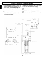
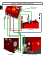
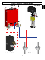
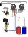
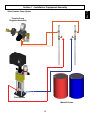
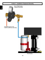
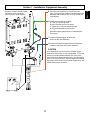
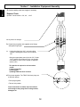
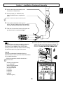
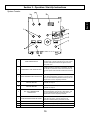
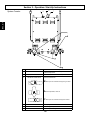
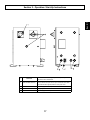
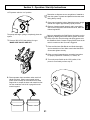
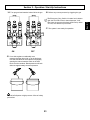
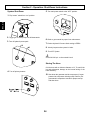
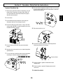
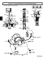
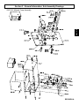
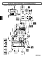
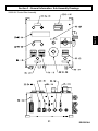
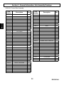
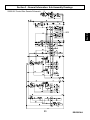
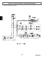
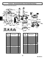
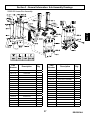
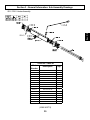
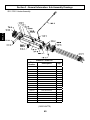
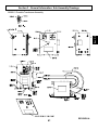
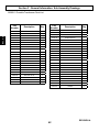
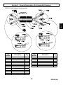
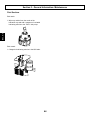
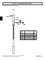
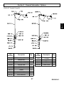
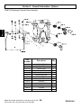
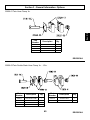
GUARDIAN
USER MANUAL
MMH 306/312
Mobile Modular Hydraulic Dispensing System
Table Of Contents
Section 1 Installation
1:1 Introduction ........................................................................................................................................................
1:2 Standard Equipment ..........................................................................................................................................
1:3 Specifications .....................................................................................................................................................
1:4 Equipment Assembly ..........................................................................................................................................
1
2
3
4
Section 2 Operation
2:1 Start-up Instructions ........................................................................................................................................... 15
2:2 Shut–down Instructions ...................................................................................................................................... 24
2:3 Daily Start-Up Instructions ................................................................................................................................. N/A
Section 3 General Information
3:1 Assembly Drawings ............................................................................................................................................. N/A
3:2 Sub Assembly Drawings ......................................................................................................................................26
3:3 Maintenance ........................................................................................................................................................ 44
3:4 Troubleshooting ................................................................................................................................................... 45
3:5 Options ................................................................................................................................................................ 46
Section 4 Safety Information
4:1 General Safety .................................................................................................................................................
52
...................................................................................................................................... 56
4:3 Limited Warranty Policy ............................................................................................................ 57
4:4 Technical Assistance ................................................................................................................ 58
For Your Reference ............................................................................................. INSIDE BACK COVER
4:2 Notes
N/A = Non Applicable
The information in this document is intended only to
indicate the components and their normal working
relationship typical use. Each assembly should be
directed by a GlasCraft distributor or made from the
GlasCraft Assembly instructions provided.
Before operating, maintaining or servicing any
GlasCraft system, read and understand all of the
technical and safety literature provided with GlasCraft
products. If you do not have the proper or related
manuals and safety literature for your GlasCraft system,
contact your GlasCraft distributor or GlasCraft,Inc.
This manual provides information for the assembly, operation, maintenance and service of this GlasCraft product as
used in a typical configuration. While it lists standard specifications and procedures, some deviations may be found.
In this GlasCraft technical and safety publication, the
following advisories will be provided where appropriate:
Is information about the procedure in progress.
In order to provide our users with the most up-to-date
technology possible, we are constantly seeking to improve
products. If technological change occurs after a product is
on the market, we will implement that technology in future
production and, if practical, make it available to current
users as a retrofit, up-date or supplement. If you find some
discrepancy between your unit and the available documentation, contact your GlasCraft distributor to resolve the
difference. GlasCraft, Inc. reserves the right to change or
modify this product as it deems necessary.
Is imperative information about equipment protection.
CAUTION
Indicates a hazardous situation which, if not avoided,
could result in minor or moderate injury.
WARNING
Careful study and continued use of this manual will provide a better understanding of the equipment and process,
resulting in more efficient operation, longer trouble-free
service and faster, easier troubleshooting.
Indicates a hazardous situation which, if not avoided,
could result in death or serious injury.
ELECTRICAL SHOCK HAZARD
Indicates a hazardous situation which, if not avoided,
could result in electrical shock or serious injury.
Sec. 1:1
Section 1 - Installation: Introduction
Sec. 1:2
Section 1 - Installation: Standard Equipment
Model - GUARDIAN MMH 306 / 312
Standard Equipment 312
Standard Equipment 306
Part
Description
Number
22808-00
HOSE MOUNTING KIT
22809-00
MATERIAL TRANSFER KIT
22810-00
ELECTRICAL WIRE WAY KIT
22878-00
HOSE SUPPORT KIT
22879-00
CONTROL CABLE KIT
22023-02
HIGH PRESSURE HOSE 50 FT.
GC-1401
USER MANUAL
SM-1424
PARTS LIST
SM-1425
PARTS LIST
Part
Number
Description
22895-02
CONTROL BOX
22870-02
MATERIAL PUMP
22885-02
HEATER BOX ASSEMBLY
22808-00
HOSE MOUNTING KIT
22809-00
MATERIAL TRANSFER KIT
22810-00
ELECTRICAL WIRE WAY KIT
22878-00
HOSE SUPPORT KIT
22879-00
CONTROL CABLE KIT
22023-02
HIGH PRESSURE HOSE 50 FT.
GC-1401
USER MANUAL
SM-1424
PARTS LIST
SM-1425
PARTS LIST
MMH 306
Material Ratio:
1:1 (Fixed)
Material Viscosity:
200- 2000 Centipoise (Cps) At Operating Temperatures
Output:
Gallons Per Cycle = .042
Liters Per Cycle = .159
Operating Temperatures:
32º F ( 0º C ) - 190º (88 º C )
Operating Psi: 3000 Psi. Max (Over Psi Switches Set)
Hydraulic Psi To Pumps:
Purging:
Electrical Requirements:
2:1 Ratio
1000 PSI. Hydraulic PSI.
2000 PSI. Fluid PSI. Per Side.
Automatic Pneumatic, Solvent-free, Constant (Probler / Probler P2)
68 Amps @ 208/240 Vac, 50/60 Hz Single Phase 5 HP
28 Amps @ 208/240 Vac, 50/60 Hz Three Phase 5 HP
Compressed Air Requirements:
15 Cfm @ 100 Psi / 425 Liters @ 6.8 Bar
Max Hose Length:
310 ft.X3/8 in. I.d. Hose Includes 10 ft.X¼ in. I.d. Heated Whip Hose
MMH 312
Material Ratio:
1:1 (Fixed)
Material Viscosity:
200- 2000 Centipoise (Cps) At Operating Temperatures
Output:
Gallons Per Cycle = .042
Liters Per Cycle = .159
Operating Temperatures:
32º F ( 0º C ) - 190º (88 º C )
Operating Psi: 3000 Psi. Max (Over Psi Switches Set)
Hydraulic Psi To Pumps:
2:1 Ratio
1000 PSI. Hydraulic PSI.
2000 PSI. Fluid PSI. Per Side.
Purging:
Automatic Pneumatic, Solvent-free, Constant (Probler / Probler P2)
Electrical Requirements:
28 Amps @ 208/240 Vac, 50/60 Hz Three Phase Compressed Air Requirements:
15 Cfm @ 100 Psi / 425 Liters @ 6.8 Bar
Max Hose Length:
310 ft.X3/8 in. I.d. Hose Includes 10 ft.X¼ in. I.d. Heated Whip Hose
Sec. 1:3
Section 1 - Installation: Specifications
Sec. 1:4
Section 1 - Installation: Equipment Assembly
1. Before attaching any components or modules, read
MOST trailer wall frames are 16in. on center. contact
your trailer manufacturer for any questions.
and study the following instructions and layout diagrams carefully. remember tongue weight and
balance are very important when planing your trailer
layout and placing heavy components such as the
air compressor and generator.
If the heater box and control box CANNOT be attached
as shown be sure they are no more than 8ft. apart .
The fluid section should be securely attached to the
trailer floor or wheel well BEFORE attaching the upper
bracket to the trailer wall.
2. GlasCraft recommends that the control box, heater
box, and fluid section are attached to the trailer wall
as shown to allow the supplied cables and hose to
reach with no interferences.
Hoses & Hose Clamps
Part
Hose marking
Number
Number
Most hoses will require multiple hose clamps unless
noted. Also note that recommended quantities and
mounting locations will vary based on the layout of
components. It is strongly recommended that all
hoses are marked according to there mating
component.
I.E.
Size
Min Bend Max Operating
Radius
PSI
7478-00
3420-04
1/4 in. i.d.
1 in.
21341-00
3800-08
1/2 in. i.d.
4 in.
3300
3500
T4-155-04
3130-12
3/4 in. i.d.
5 in.
1250
ISO hoses = Wrap with “red” tape
POLY hoses = Wrap with “blue” tape.
Also mark thermocouple extension cords (22826-00).
A = “red”
B = “blue”
Thermocouple hose = unmarked
3. Attach the rails p/n 22837-00 to the trailer wall with
Minimum Bend Radius for Glas Craft Hoses
self-taping screws p/n 21953-32.
When attaching the hose clamp rails, conduit clamps,
or cables it is recommended that they be attached
to trailers structure.
Wires & Cables
4. Route and attach the hose control wires from the
I.E. Wall or ceiling studs, heavy gauge steel or
aluminum, or plywood 3/8in. or greater.
portable transformer (22290-01) to the control panel
(22895-00), using the convoluted sleeving (22813-00)
with straps (22814-03) and hardware (22706-24). Refer
to the point to point diagram.
- Hydraulic Control Hose p/n 18007-25 Attach with
hose clamps p/n 22835-01 (Qty. 6).
When routing the control cables for the hydraulic power
pack and the transformer (22824-00). mark the cables
so that you can identify them easily.
- Hydraulic PSI feed and Return to Tank Hoses
p/n 22898-00 Attach with hose clamps p/n 22836-01
(Qty. 6).
After routing and attaching power cords, it maybe
necessary to strip wires and attach crimp-on connectors.
- Pump to Heater Transfer Hoses
p/n’s 22938-05 (A-side) & 22938-06 (B-side) Attach
with hose clamps p/n 22836-01 (Qty. 1).
- Strip back the rubber cover from the wire bundle and
route the individual wires through the console and
wire-way.
- Transfer feed Hoses (Transfer Pump to Main Pump Inlet)
p/n 22897-00 Attach with hose clamps p/n 22836-02
(Qty. 4).
- Cut the wires to required length.
- Recirculation Hoses (From 3-way common out to drum)
p/n’s 18007-25 (A-side) & 18008-25 (B-side) Attach
with hose clamps p/n 22836-02 (Qty. 4).
- Strip the insulation off of each wire, approx. 3/8in..
- Crimp the required lugs on each wire using crimps
capable of achieving a 1/4in. wide depression. The
wire should not be loose in the crimp. Check by
twisting and pulling on both the wire and terminal.
Refer to the point to point diagrams.
Sec. 1:4
Section 1 - Installation: Equipment Assembly
Sec. 1:4
Section 1 - Installation: Equipment Assembly
Control Panel
Main power cable
to breaker box
Heater Box
Transformer
Hydraulic Power Pack
Heater Box
Fluid Section
Recirculation Block
Pick-Up Tubes
Sec. 1:4
Section 1 - Installation: Equipment Assembly
Sec. 1:4
Section 1 - Installation: Equipment Assembly
Diaphragm Transfer Pump Option
Transfer Pump
Regulator Assembly
Pick-Up Tubes
Fluid Section
Material Drums
Section 1 - Installation: Equipment Assembly
Sec. 1:4
Stick Transfer Pump Option
Transfer Pump
Regulator Assembly
Fluid Section
Material Drums
Sec. 1:4
Section 1 - Installation: Equipment Assembly
Gun / Fluid Section
Regulator Assembly
Supplied trigger air line
from the main hose assembly
Fluid Section
10
5. Connect hose assembly, p/n: 22023-02 to the
Extention cord p/n: 22826-16 from
the bottom of the control box.
(refer to point to point diagram)
front of the heater box module. The fittings are sized
differently and will attach only one way. (match like
sized fittings).
6. Install thermocouple at tee fitting.
a. Feed 12’ line through hose.
b. Nut & Ferrules will lock into fitting.
c. Tighten nut 1-1/4 turns past finger tight.
d. Plug thermocouple into control box.
Note: When replacing thermocouple p/n: 21874-00 use kit
p/n: 21214-01.
7. Connect supplied trigger air line to the
air line on the hose assembly.
8. Connect the twist-lock plugs from the transformer
module to the plugs on the hose assembly.
CAUTION
Hose assemblies are constructed of durable, rugged
materials,however they are not indestructible. To provide
precisely controlled heated material, the hoses have
electrical wiring wrapped between layers. Avoid dragging
hoses over or around sharp, abrasive edges and corners.
Exercising caution and common sense will give long, and
reliable service from the hoses.
11
Sec. 1:4
Section 1 - Installation: Equipment Assembly
Section 1 - Installation: Equipment Assembly
Sec. 1:4
9. Continue adding extra hose lengths if necessary.
Required Tools:
Opened - end wrenches - 5/8”, 3/4” , 13/16”
a. Lay hoses out straight.
b. Couple hoses together with supplied union fittings
and tighten finger-tight.
c. • Hold crimp fitting hex (3/4”), and union fitting
together, allowing the hose to hold it’s natural
line.
• Using the appropriate wrench (A-side 3/4” / B-side
13/16”) tighten swivel fitting to union, not allowing
crimp fitting or union to turn. Repeat on opposite side of union.
This practice is required on all connection
points.
1) Hose @ machine
2) Hose @ gun
3) Adding additional hose sections
d. Plug hoses together, The TRU-FLOW hose plugs are
a twist-lock design.
• Push plugs together.
• Twist to lock position.
Once connections are made, tape connections
well enough to keep plugs from coming undone,
damaged, etc.
12
Sec. 1:4
Section 1 - Installation: Equipment Assembly
10. Connect the whip hose assembly to the
last section of material hose.
11. Connect jumper p/n: 22094-00 to the
plugs on material hose to complete the
circuit.
Jumper not needed with 18006-01 heated whip hose.
12. Connect Hose Assembly and the gun as
shown. The swivel fittings on the Hose assembly
are sized differently and will attach only one way.
13. Fluid and air connections between the sytem and
gun should now be complete and tight.
STE
transformer
H1
When Main Power to system console is on, the white
and black wires in the console are always live!
Disconnect or turn off Main Power source before
opening console to make any repairs or before making
any electrical repair of any type to the system.
PRIMARY
H2
14. If more than 50 ft. of hose is used the transformer tap
ARIA
setting will need to
be set
length. The
COM
15V for
30Vproper
45V hose
60V 5V
TO say
HOSE
sticker on the front cover will
which tap to move
the wire to. DOCONNECTIONS
NOT MOVE THE HOSE
COMMON
LEG!
LENGTH
COM
(DO NOT
MOVE)
15V
30V
45V
60V
60V
5V
If you do not understand the electrical hook-up
described above, consult your local GlasCraft distributor
OR a qualified electrician.
50
100
150
200
250
300
FT
FT
FT
FT
FT
FT
ARI
AR
Electrical connections must be checked on a
periodic basis.
208/240 volt single phase
L1 L2 GROUND
208/240 volt three phase
L1 L2 L3 GROUND
380 volt three phase
L1 (black)
L2 (brown)
L3 (black)
L4 (blue)
GROUND (green)
13
9500
D
SIZE: (ref.): 4" X 4-1/4"
Sec. 1:4
Section 1 - Installation: Equipment Assembly
15. Fill the hydraulic power pack with proper fluid.
16. Fill the ISO pump lube bottle on top of the fluid section
with DBP or material supplier’s recommended lubricant.
The hydraulic pack tank is empty when shipped
from GlasCraft. The tank MUST be filled before
operation. Tank Capacity: 20 GAL. / 75.5 Liter.
Recommended Hydraulic Fluid: ISO grade 32, 46,
or 68. Fluids containing anti-wear additives are
recommended for optimum service life.
Fill Cap
Fill Gauge
14
Section 2 - Operation: Start-Up Instructions
Sec. 2:1
System Console
MAIN POWER SWITCH
Controls power and door; handle must point 1 to
energize power , handle must point to 0 to open control
box door. White pilot indicates when lighted, that the
main power is on.
EMERGENCY STOP PUSH BUTTON
To stop all functions, push down on red button. To reset,
turn handle on push button. All functions will remain off
until main power switch has been switched off and back
on
3
HOSE TEMPERATURE CONTROLLER
Controls temperature of liquid inside the heated hoses.
To set desired temperature, press the up or down button
until you reach desired temperature From this point, the
temperature control is completely automatic.
4
ON PUSH BUTTON
Powers the controller. It requires 10 seconds for the
Controller to respond.
5
ON PUSH BUTTON
Powers the controller. It requires 10 seconds for the
Controller to respond.
6
ISO / POLY TEMPERATURE
CONTROLLER
7
OVER-PRESSURE RESET BUTTONS
1
2
8
ON PUSH BUTTON
9
OFF PUSH BUTTON
10
COUNTER
Controls temperature of liquid inside ISO heater. To set
desired temperature, press the up or down button until
you reach desired temperature. From this point, the
temperature control is completely automatic.
When over-pressure is detected, the hydraulic power
pack will be shut down, and will remain off until
pressure is reduced and the push button is reset.
Power On To the hydraulic power pack.
Power Off to the hydraulic power pack.
Counts pumps cycles. .042 GPC / .021 GPS
15
Section 2 - Operation: Start-Up Instructions
System Console
6
7
Sec. 2:1
5
1
PSI GAUGES
2
THERMOCOUPLE FITTING
3
OVERPRESSURE SWITCHES
4
RECIRCULATION VALVE
Monitors ISO / POLY material pressure
Thermocouple wire is feed through here to monitor
material temperature.
Monitors ISO / POLY material overpressure.
Controls material flow.
B Valve open to recirculate through the gun block.
A Normal operation, valve off.
C Valve open to recirculate through the heaters.
5
6
CONTROL CABLE
POWER CORD
7
POWER LAMP
16 Pin plug.
Inlet cord grip for power cable.
Indicates power is supplied to the cabinet.
16
Sec. 2:1
Section 2 - Operation: Start-Up Instructions
1
AMMETER
2
MAIN POWER SWITCH
An instrument for measuring amperes to the primary
side of the hose’s transformer.
Controls power and door; handle must point 1 to energize
power, handle must point to 0 to open control box door. White
pilot indicates when lighted, that the main power is on.
3
MAIN POWER CORD
4
CONTROL CABLE PLUG
4 pin plug.
Inlet cord grip for the main power.
5
HOSE POWER CABLES
Inlet cord grips for hose power cables.
17
Sec. 2:1
Section 2 - Operation: Start-Up Instructions
1
RUN/RETRACT SWITCH
2
PSI GAUGE
3
REMOTE VALVE
4
AIR CONNECT ELBOW
5
COUNTER CABLE BOOT
6
OUTLET FITTINGS
7
INLET FITTINGS
18
The retract switch places the material
pumps in the full “down stroke” position.
Hydraulic pressure gauge.
Hydraulic pressure adjustment.
Air inlet elbow fitting.
Rubber boot for the counter cable.
Material pump outlet fittings.
Material pump inlet fittings.
Sec. 2:1
Section 2 - Operation: Start-Up Instructions
7
1
POWER CABLE
2
CONTROL CABLE
Inlet cord grip for the power cable.
3
POWER LAMP
Indicates power is on.
4
DRAIN VALVE
Open the valve to drain the hydraulic oil.
5
FILL LEVEL GAUGE
6
FILL PORT
7
FILTER HOUSING
4 pin plug.
Monitors the Hydraulic oil level when filling.
Remove cap to fill the tank with hydraulic oil.
Cartridge filter.
19
Section 2 - Operation: Start-Up Instructions
If the transfer pumps can not move material adequately
enough to properly prime the system it may be necessary
to start the hydraulic power pack.
Sec. 2:1
Never leave machine unattended while system power is
on or system is running.
System running is defined as: preheat cycle of the hose
heat, primary heaters, or any pump operation.
Machine operators must be familiar with the component
functions and operation of the machine.
a. Ensure the hydraulic pressure knob is turned
completely counter clockwise.
Pre-Operation Check List
A. Check that all fittings are securely tight.
B. Check electrical hook-up (qualified electrician
recommended).
C. Main power switch on Control Box should be
switched to OFF position.
b. Turn the main power switch to the “ON”
position.
Do not place any part of the body in the path of the
material spray.
Do not point the gun at or near other personnel.
Do not look into the Mixing Chamber orifice at any time.
Because of the hazardous materials used in this equipment, it is recommended that the operator use an air
mask, goggles, protective clothing, and other safety
equipment as prescribed by current regulations, recommendations of the chemical suppliers, and the laws in
the area where the equipment is being used.
Initial Start-Up Procedure
The system is now ready for start-up.
Filling The System
1. Start the generator and air-compressor (If a gas powered air-compressor is being used). Refer to your
generator/air-compressor manual for proper start-up
and shut-down.
2. The system is now ready to be filled with material.
With transfer pumps in place, adjust regulators on
transfer pumps to 30-50 psi or until the pumps begin
cycling, once the pumps begin loading up (cycle rate
slows or stops) increase transfer pump air pressure
to 100 psi. to fill the system.
20
c. Turn on the hydraulic power pack.
Section 2 - Operation: Start-Up Instructions
d. Flip retract switch to “run” position.
5. Close manual material valves. Material pressure gauges
should now register approximately equal pressure.
6. Dispose of waste material properly and in accordance
with chemical suppliers instructions and local, state and
federal regulations.
The pumps will begin cycling to completely prime the
system
Before re-assembling the Side Blocks, lubrication can be
applied by dabbing some white lithium grease into holes
inside of the Gun Front Housing and wiping grease over
the SideBlock Seals. Grease will purge itself when the air
valve is turned on at the Gun and is triggered.
3. Remove ISO & POLY side blocks from gun.
MAKE SURE VALVES ARE OFF!
7. Clean and lubricate Side Blocks and Seals thoroughly
and re-assemble on Gun. Make certain that Side Block
Screws are tighten securely.
8. Refer to material manufacturers operating instructions
for proper preparation of material, i.e, mixers, etc.
9. Turn main power Switch to the “ON” position, if the
power is not all ready on from step “b”.
4. Place separate clean containers under each indi-
vidual side block. Slowly open material valves
(black arrow forward) on each side block to allow
trapped air to escape the hose and material to flow
into the containers until all air is purged from the
material system.
21
Sec. 2:1
Remember to dispense one to two gallons of material to
clear the system of grease and plasticizer that was used
during factory testing.
Section 2 - Operation: Start-Up Instructions
10. Turn on hose control:
12. Turn on Hydraulic Power Pack
Sec. 2:1
a. Push in the green button.
b. Press either up or down arrow buttons on the
controller until desired temperature setting
is achieved.
Allow enough time for hose to warm up (approximately
30 minutes). Remember that the heated hose does not
have a delta rating. The heated hose’s function is to
maintain the heat generated by the primary heaters
during system operation, and preheat material during
initial start-up. The hose should be set to maintain a
temperature close to the set point of the primary heaters.
11. Turn on the ISO & POLY Heaters.
To see the actual temperature of the liquid in the hose,
push the blue button once and release. The actual
temperature will then be displayed for 10 seconds.
13. Adjust temperature to desired setting. ISO and
POLY controllers function exactly the same as the
hose controller.
Allow enough time for the material to be heated
(approximately 3-5 minutes).
Turn transfer pump air regulator on slowly. Pumps
should cycle slowly until hoses are full of material.
14. Slowly adjust Hydraulic PRESSURE KNOB clockwise
on the system to desired pressure.
Straighten hose out flat, to avoid uneven heating and
damage to internal wiring of the hose assembly.
Pressure Knob
22
Section 2 - Operation: Start-Up Instructions
16. Relieve any excess pressure by triggering the gun.
The Emergency Stop Switch is located on the bottom
right side of the Box Panel, when depressed, it will
shut down the power and activate the Air Dump Valve.
To reset, turn handle on push button.
17. The system is now ready for operation.
ON
OFF
15. If one side registers considerably more
pressure than the other side, go to the high pres-
sure side and bleed off some pressure by slightly
opening the manual material valve on the side
block over the container. Bleed pressure until both
sides are approximately the same pressure.
Material will dispense at high pressure. follow all safety
precautions
23
Sec. 2:1
14. Turn purge air and material valves ON at the gun.
Section 2 - Operation: Shut-Down Instructions
System Shut-Down
5. Turn main power switch to the “OFF” position.
Sec. 2:2
1. Flip “retract” switch from “run” position.
2. Trigger gun to send pumps into full downstroke.
3. Turn off hydraulic power pack.
6. Refer to gun manual for proper Gun maintenance.
7. Reduce Hydraulic Pressure Knob setting to ZERO.
8. Visually inspect entire system for leaks.
9. Turn OFF System.
Leave 200-500 psi. on the material circuit.
Storing The Hose
4. Turn off primary heaters.
Coil the hose with a minimum diameter of 4’, To avoid kinking and subsequent damage to the internal wiring of the
hose assembly.
10. Shut down the generator and air-compressor (If a gas
powered air-compressor is being used). Refer to your
generator/air-compressor manual for proper start-up
and shut-down
24
Section 2 - Operation: Daily Start-Up Instructions
System Daily Start-Up
8. Once the hose temperature reaches 120º, It’s ok to turn
on the primary heaters and set temperature to material
suppliers specifications.
1. Start-up the generator and air-compressor (If a gas
Sec. 2:3
powered air-compressor is being used). Refer to
your generator/air-compressor manual for proper
start-up and shut-down.
2. Uncoil hose.
3. Check desiccant dryer beads to insure they are
still purple and have not changed to pink.
4. Check the ISO pump lube bottle on top of the fluid
section and add DBP or material supplier’s reccommended lubricant if needed.
5. Check material screens at the gun and transfer
9. Flip retract switch to “run”
10. Increase Hydraulic pressure to desired pressure.
Balance pressures if necessary.
pumps.
6. Start the drum mixer and it run to material suppliers
specifications.
7. Turn on the hose controller and set the temperature
according to material supplier’s specifications.
Pressure Knob
11. Perform probler / probler P2 side block seal
integrity test.
12. Perform probler / probler P2 high-pressure ball
valve test.
13. READY TO SPRAY!
25
Section 3 - General Information: Sub Assembly Drawings
Sec. 3:2
22870-XX Material Pump Assembly
26
REVISION A
Section 3 - General Information: Sub Assembly Drawings
Sec. 3:2
22870-XX Material Pump Assembly
27
REVISION A
Section 3 - General Information: Sub Assembly Drawings
Sec. 3:2
22870-XX Material Pump Assembly
28
REVISION A
22870-XX Material Pump Assembly
Part
Number
Description
Qty.
Part
Number
Description
Qty.
22847-00
TOP CHANGEOVER PLATE
1
22848-00
BOTTOM CHANGEOVER PLATE
1
RM-856-03
ELBOW FITTING
1
22856-00
TOP CYLINDER PLATE
1
RS-118
ISO DECAL
1
22859-00
HYDRAULIC CYLINDER
1
RS-119
POLY DECAL
1
22871-00
CHANGEOVER STANDOFF
4
10009-02
ELBOW FITTING
2
22881-00
CHANGEOVER GUARD
1
10009-20
ELBOW FITTING
1
22888-00
MOUNTING PLATE
1
10599-40F
SCREW
2
22889-00
MOUNTING PLATE
1
19858-00
PUMP STANDOFF
2
22893-00
FITTING
1
19859-00
UNIVERSAL PLATE
1
22894-00
PLUG FITTING
2
19861-00
PUMP SADDLE
1
22896-01
HOSE ASSEMBLY
1
19984-00
AIR MOTOR STANDOFF
4
22896-02
HOSE ASSEMBLY
1
20053-12C
SCREW
4
23204-01
PRESSURE GAUGE
1
20188-20C
SCREW
18
23411-00
ELBOW FITTING
1
20732-03
TUBING
2 FT.
23482-00
GLASCRAFT DECAL
1
20735-01
ELBOW FITTING
1
23718-00
PLASTIC BOTTLE
1
20735-04
ELBOW FITTING
5
23747-00
BOTTLE BRACKET
1
20796-02
FITTING
1
7486-05
WASHER
14
20796-04
FITTING
2
7486-05
WASHER
33
20804-56C
SCREW
4
7486-07
WASHER
4
21081-02
CONNECTOR
1
7486-10
WASHER
6
21192-01
2-WAY VALVE
1
7486-13
WASHER
4
21308-40C
SCREW
4
7486-27
WASHER
6
21323-00
FLEXIBLE CONDUIT
2.5 FT.
7729-10
HEX NUT
2
21390-01
AIR MOTOR STANDOFF
4
7733-06
HEX NUT
2
21613-80C
SET SCREW
4
7733-12
HEX NUT
4
21660-00
2-WAY VALVE
1
7733-14
HEX NUT
4
21806-00
LEFT GUARD
1
7733-17
HEX NUT
4
21807-00
RIGHT GUARD
1
7733-34
HEX NUT
8
21835-00
1:1 PUMP
1
7734-03
HEX NUT
10
21835-01
ISO 1:1 PUMP
1
7734-06
LOCK WASHER
30
22007-02
FITTING
1
7734-07
LOCK WASHER
4
22010-01
HOSE ASSEMBLY
2
7734-12
LOCK WASHER
4
22083-00
“RUN” DECAL
1
7735-40C
SCREW
2
22084-00
“RETRACT” DECAL
1
7957-32F
SCREW
2
22101-00
LIMIT SWITCH
1
7957-56C
SCREW
4
22107-05
ELBOW FITTING
1
7959-20C
SCREW
4
22115-01
CAM SHAFT ADAPTER
1
8155-40C
SCREW
4
22139-00
MOUNTING BRACKET
1
8156-48C
SCREW
4
22164-00
VALVE
2
8301-40C
SCREW
4
22212-02
BULKHEAD FITTING
1
8560-03
FITTING
2
22831-00
REDUCER FITTING
1
8560-04
FITTING
1
22834-00
FITTING
2
8560-27
FITTING
1
22838-00
TEE FITTING
1
9704-11
TUBING
6 FT.
22839-00
TEE BRANCH FITTING
1
22846-00
FRONT CHANGEOVER PLATE
1
29
REVISION A
Sec. 3:2
Section 3 - General Information: Sub Assembly Drawings
Section 3 - General Information: Sub Assembly Drawings
Sec. 3:2
22895-XX Control Box Assembly
30
REVISION A
Section 3 - General Information: Sub Assembly Drawings
Sec. 3:2
22895-XX Control Box Assembly
31
REVISION A
Section 3 - General Information: Sub Assembly Drawings
22895-XX Control Box Assembly
Sec. 3:2
Part
Number
Description
Qty.
Part
Number
Description
Qty.
RS-118
ISO DECAL
2
22154-00
HYDRAULIC POWER DECAL
2
RS-119
POLY DECAL
2
22157-00
TERMINAL BLOCK
4
RS-121
HOSE DECAL
2
22158-00
BLOCK SPACER
4
RS-122
PRIMARY DECAL
2
22159-00
TERMINAL BLOCK COVER
1
RS-124
MAIN DECAL
1
22171-01
SWITCH BLOCK
1
RS-127
HOSE CONTROL DECAL
2
22178-00
POWER SWITCH
1
RS-141-02
CORD GRIP
1
22414-00
CYCLE COUNTER DECAL
1
T4-161-01
CABLE RELIEF CONNECTOR
1
22422-01
RELAY
2
T4-161-03
CABLE RELIEF CONNECTOR
2
22422-02
RELAY
1
14638-02
RIVET
4
22423-01
SOCKET RELAY
2
17702-00
PILOT LAMP
1
22423-02
SOCKET RELAY
1
CIRCULAR PANEL JACK
3
21112-00
LCD COUNTER
1
22502-00
21284-16C
SCREW
8
22528-00
21356-01
MICROPROCESSOR CONTROL
3
22753-00
OVERPRESSURE/OVERTEMP DECAL
1
21586-03
CORD GRIP
1
22816-00
PANEL MOUNT HOUSING
2
21823-00
DIN RAIL
1
22818-00
FEMALE CONNECTOR
2
21824-16C
SCREW
6
22819-00
PANEL BASE MOUNT
1
21854-00
LATCHED PUSH BUTTON
2
22822-00
TERMINAL INSERT CONNECTOR
1
21862-00
MOMENTARY PUSH BUTTON
3
22890-00
CONTROL BOX
1
21863-00
PUSH BUTTON
1
22891-00
MOUNTING PAD
2
21864-00
EMERGENCY STOP PUSH BUTTON
1
22892-00
MOUNT PAD
2
21865-01
N.O. CONTACT BLOCK
5
23482-00
GLASCRAFT DECAL
1
WIRING DUCT
2
21865-02
N.C. CONTACT BLOCK
3
5307-01
CONDUIT NUT
2
21866-00
COUPLING PLATE
7
5307-03
CONDUIT NUT
3
21867-02
BLACK INSCRIPTION CAP
1
7486-27
WASHER
6
21867-03
WHITE INSCRIPTION CAP
2
7486-28
WASHER
4
21867-04
WHITE INSCRIPTION CAP
1
7733-02
HEX NUT
8
21867-05
WHITE INSCRIPTION CAP
2
7733-06
HEX NUT
6
21886-00
LAMP MOUNTING BLOCK
6
7734-01
LOCK WASHER
8
21887-01
YELLOW CAP
2
7734-03
LOCK WASHER
6
21887-02
OPAQUE CAP
1
8156-16C
SCREW
4
21887-03
GREEN CAP
2
21889-00
DIN RAIL FUSE HOLDER
6
21892-01
FINDER RELAY
3
21893-01
SOCKET RELAY
3
21953-64
SELF-TAP SCREW
4
22104-00
EMERGENCY STOP DECAL
1
22142-00
TRANSFORMER
1
22150-02
OPAQUE PILOT LIGHT
1
32
REVISION A
Section 3 - General Information: Sub Assembly Drawings
Sec. 3:2
22895-XX Control Box Generic Schematic
33
REVISION A
Section 3 - General Information: Sub Assembly Drawings
Sec. 3:2
22895-XX Control Box Schematic
34
REVISION A
Section 3 - General Information: Sub Assembly Drawings
Sec. 3:2
22895-XX Control Box Schematic
35
REVISION A
Section 3 - General Information: Sub Assembly Drawings
Sec. 3:2
22875-XX Heater Box Assembly
Part
Number
Description
Qty.
Part
Number
Description
Qty.
RS-141-02
CORD GRIP
2
22873-00
CONTROL BOX COVER
1
RS-141-03
CORD GRIP
1
22876-00
FLUID MANIFOLD A SIDE
1
14638-02
RIVET
2
22877-00
FLUID MANIFOLD B SIDE
1
17702-00
PILOT LAMP
1
23445-00
ISO HEATER
1
20188-16C
SCREW
11
23446-00
POLY HEATER
1
20188-20C
SCREW
4
23479-04
ELECTRICAL ASSEMBLY
1
20226-00
SET SCREW
1
5307-01
CONDUIT NUT
2
21094-01
ELBOW FITTING
2
5307-02
CONDUIT NUT
1
21317-01
FITTING
2
7315-11
RUBBER GROMMET
2
21866-00
COUPLING PLATE
1
7486-11
WASHER
2
21886-00
LAMP MOUNTING BLOCK
1
7486-28
WASHER
2
22150-02
PILOT LIGHT
1
7733-06
HEX NUT
1
22162-00
CONNECTOR
1
7734-03
LOCK WASHER
1
22814-01
LOOP STRAP
2
7734-06
LOCK WASHER
15
22819-00
PANEL MOUNT
1
7735-40C
22822-00
TERMINAL CONNECTOR
1
8160-12F
36
SCREW
SET SCREW
1
4
REVISION A
Section 3 - General Information: Sub Assembly Drawings
Sec. 3:2
22885-02 Heater Box Assembly
Part
Number
Description
Qty.
Part
Number
Description
Qty.
RS-141-02
CORD GRIP
2
22876-00
FLUID MANIFOLD A SIDE
1
FLUID MANIFOLD B SIDE
1
RS-141-03
CORD GRIP
1
22877-00
14638-02
RIVET
2
22939-00
GUARDIAN MMH DECAL
1
22944-00
MMH 12000 DECAL
1
17702-00
PILOT LAMP
1
20188-16C
SCREW
11
23479-08
ELECTRICAL ASSEMBLY
1
20188-20C
SCREW
7
23490-00
ISO HEATER
1
23491-00
POLY HEATER
1
20226-00
SET SCREW
1
21094-01
ELBOW FITTING
2
5307-01
CONDUIT NUT
2
CONDUIT NUT
1
21317-01
FITTING
2
5307-02
21866-00
COUPLING PLATE
1
7315-11
RUBBER GROMMET
2
WASHER
2
21886-00
LAMP MOUNTING BLOCK
1
7486-11
22150-02
PILOT LIGHT
1
7486-28
WASHER
2
HEX NUT
1
22162-00
CONNECTOR
1
7733-06
22814-01
LOOP STRAP
2
7734-03
LOCK WASHER
1
LOCK WASHER
15
22819-00
PANEL MOUNT
1
7734-06
22822-00
TERMINAL CONNECTOR
1
7735-40C
22873-00
CONTROL BOX COVER
1
8160-12F
37
SCREW
SET SCREW
1
4
REVISION A
Section 3 - General Information: Sub Assembly Drawings
22876-00 Fluid Manifold Assembly
Sec. 3:2
22876-00
Part
Number
Description
Qty.
8462-09
FITTING
1
8560-08
HOSE FITTING
2
8560-17
HOSE FITTING
1
9488-02
ELBOW FITTING
1
11021-22
PIPE PLUG
1
11021-23
PIPE PLUG
1
20263-00
VALVE
1
21094-01
ELBOW FITTING
1
21830-00
OVERPRESSURE SWITCH
1
22519-00
GAUGE
1
22843-00
FLUID MANIFOLD
1
REVISION A
22877-00 Fluid Manifold Assembly
22877-00
11021-23
38
Part
Number
Description
Qty.
8462-09
FITTING
1
17597-01
FITTING
1
18371-00
HOSE FITTING
2
11021-23
PIPE PLUG
1
19488-02
ELBOW FITTING
1
20263-00
VALVE
1
21094-01
ELBOW FITTING
1
21315-00
HOSE FITTING
1
21830-00
OVERPRESSURE SWITCH
1
22519-00
GAUGE
1
22843-00
FLUID MANIFOLD
1
REVISION B
Section 3 - General Information: Sub Assembly Drawings
Sec. 3:2
ISO / POLY Heater Assembly
23445-00 / 23446-00
Part
Number
Description
Qty.
11021-23
PLUG
1
13076-18
O-RING
4
20653-00
FITTING
1
21068-06C
SCREW
4
21074-00
THERMOCOUPLE
1
22108-00
OVERTEMP SWITCH
2
23442-00
HEATER FRONT CAP
1
23443-00
HEATER REAR CAP
1
23444-00
HEATER BODY
1
23483-01
ELECTRIC PLUG
2
23484-01
ELECTRIC PLUG
2
23486-01
ELECTRIC PLUG
2
23487-01
ELECTRIC PLUG
2
7734-01
LOCK WASHER
4
7734-06
LOCK WASHER
12
7959-56C
SCREW
12
(6000 WATTS)
39
Section 3 - General Information: Sub Assembly Drawings
Sec. 3:2
ISO / POLY Heater Assembly
23490-00 / 23491-00
Part
Number
Description
Qty.
11021-23
PIPE PLUG
4
13076-18
O-RING
8
1
20653-00
FITTING
21068-06C
SCREW
8
21074-00
THERMOCOUPLE
1
22019-00
HEATER ELEMENT
4
22108-00
OVERTEMP SWITCH
4
23444-00
HEATER BODY
2
23483-01
FEMALE ELECTRICAL PLUG
1
23484-01
MALE ELECTRICAL PLUG
1
23486-01
FEMALE ELECTRICAL PLUG
1
23487-01
MALE ELECTRICAL
1
23488-00
HEATER TOP CAP
1
23489-00
HEATER BOTTOM CAP
1
7734-01
LOCK WASHER
8
7734-06
LOCK WASHER
24
7959-56C
SCREW
24
(12000 WATTS)
40
Section 3 - General Information: Sub Assembly Drawings
Sec. 3:2
22290-01 Portable Transformer Assembly
41
REVISION A
Section 3 - General Information: Sub Assembly Drawings
22290-01 Portable Transformer Parts List
Part
Number
Sec. 3:2
RS-121
Description
HOSE DECAL
Qty.
Part
Number
1
RS-126
HOSE CURRENT DECAL
1
RS-141-01
CORD GRIP
1
RS-141-04
CORD GRIP
2
13424-01
CABLE TIE
5
14638-02
RIVET
5
17702-00
PILOT LAMP
1
21119-00
TRANSFORMER
1
21129-00
TRANSFORMER DECAL
1
21145-00
VENT PLUG
8
21284-16C
SCREW
2
21308-20C
SCREW
1
21598-00
TRANSFER HOUSING SEAT
12
21823-00
DIN RAIL
0.8 Ft.
21861-00
CONDUCTOR CONNECTOR
1
21866-00
COUPLING PLATE
1
21886-00
LAMP MOUNTING BLOCK
1
21888-06
CIRCUIT BREAKER
1
21953-64
SELF-TAP SCREW
4
22088-05
ELECTRIC PLUG
2
22119-00
FUSE BLOCK
1
22143-00
FUSE
1
22146-03
SOLID STATE RELAY
1
Qty.
22150-02
PILOT LIGHT
1
22163-00
AMMETER
1
22171-01
SWITCH BLOCK
1
22178-00
POWER SWITCH
1
22201-01
MECHANICAL CONTACTOR
1
22291-00
TRANSFORMER BOX
1
22293-00
TRANSFORMER FEET BOX
22294-00
4
CAUTION DECAL
1
22296-00
TRANSFORMER DECAL
22816-00
PANEL MOUNT HOUSING
1
22818-00
FEMALE INSERT CONNECTOR
1
5307-01
7486-06
42
Description
CONDUIT NUT
1
3
WASHER
4
7486-07
WASHER
4
7486-28
WASHER
5
7733-02
HEX NUT
2
7733-12
HEX NUT
1
7733-14
HEX NUT
8
7734-01
LOCK WASHER
2
7734-02
LOCK WASHER
4
7734-06
LOCK WASHER
1
7734-07
LOCK WASHER
4
7734-12
LOCK WASHER
4
7747-12C
SCREW
4
8156-32C
SCREW
4
REVISION A
Section 3 - General Information: Sub Assembly Drawings
Sec. 3:2
22023-02 High Pressure Hose Assembly
Part
Number
Description
Qty.
10262-04
NYLON FLUID HOSE
50 ft.
11745-10
HEAT SHRINK TUBING SHRINK
1 ft.
Part
Number
Description
Qty.
19506-01
COPPER STRIP
6 lbs.
22036-00
HEAT TAPE END SEAL
4
2
13424-03
CABLE TIE
4
22088-01
MALE ELECTRIC PLUG ASSEMBLY
13424-05
CABLE TIE
1
22088-02
FEMALE ELECTRIC PLUG ASSEMBLY
2
15998-02
NEOPRENE TUBING
100 ft.
23607-00
COLD SPLICE KIT
4
17895-01
UNION FITTING
1
23608-00
SPLICE CONNECTOR
4
17896-01
UNION TUBE FITTING
1
7478-01
MATERIAL HOSE
100 FT.
17944-10
HOSE FITTING
2
18009-03
HOSE FITTING
2
18012-03
HEATED HOSE COVER
50 ft.
18101-01
ADAPTER FITTING
1
19490-01
HOSE FITTING
2
43
REVISION A
Section 3 - General Information: Maintenance
Fluid Sections
Each week:
Sec. 3:3
1. Wipe any residue from the mouth of the
lubrication cup and add 1 teaspoon of a suitable
lubricating solution to the “POLY” side pump.
Each month:
1. Change the lubricating solution in the ISO bottle.
44
Section 3 - General Information: Troubleshooting
The system incorporates monitors for high pressure
monitoring. These monitoring devices will prevent the
system from continued operation if high pressure
situations develop.
There are pressure sensors located on each side of the
hose mounting block. The high pressure sensor is
located at the outbound of the fluid section.
When main power to unit is on, the console will have wires
that are live. Disconnect or turn off main power source
before opening console to make any repairs.
Before performing any repairs on the system, ALL AIR and
FLUID PRESSURES SHOULD BE RELIEVED TO ZERO
(BLEED-OFF)!
Over Pressure Problem Correction
The high pressure monitoring sensor will engage if fluid
pressure increases above 3200 psi.
1. Determine if the problem is high pressure related.
If a high pressure situation develops, the sensor will
detect this and immediately engage the hold-in circuit.
2. Relieve system hydraulic pressure.
This will disengage power to the machine and it will
stop cycling. It will also turn the heater off.
3. Turn off main power
On the control box panel, there are two yellow lighted
push buttons marked over pressure. One of these push
buttons will be illuminated after the monitoring sensor
engages, indicating where the problem is located (ISO
or Poly).
4. Fix the problem area:
Over pressure resets
a. Potential high pressure causes:
- Restriction
- Overheating material in static position
- ISO filter at gun
5. Re-start system for operation
6. Once the power has been turned off and problem solved
and the main power is turned on again, the over
over pressure lighted buttons will automatically be reset.
For additional diagnostics refer to trouble shooting guide
GC-1380
In an over pressure situation, the system will remain
shut down until it is manually reset.
At this point, it is necessary to determine if the problem
is an over pressure situation.
When the sensor engages, the system will be frozen,
giving you the pressure readings at the time the problem
was detected.
If you do not understand the electrical hook-up described
above, consult your local GlasCraft distributor or a qualified
electrician. It is recommended that a qualified, licensed
electricianshould install power to the supply disconnect.
You should always follow all local or national electrical
codes.
Disconnect power source BEFORE attempting any repairs
or opening the Control Boxes. Access to internal parts is
limited to qualified personnel ONLY! Place the main power
breaker in the OFF position BEFORE disconnecting the
power cables. This equipment is not approved for use in
hazardous locations as set forth in the National Electrical
Code Article 500 and Sub-Part “S” of the OSHA Standards.
Inspect the fluid pressure gauges, in an over pressure
situation, one of the fluid pressure gauges will be
significantly higher than the other gauge.
45
Sec. 3:4
Over Pressure System Protection
Section 3 - General Information: Options
Sec. 3:5
22940-00 Stick Transfer Pump Assembly
Part
Number
Description
Qty.
16400-00
STICK TRANSFER PUMP
1
23471-00
FILTER
1
20735-06
ELBOW FITTING
1
8462-10
FITTING
1
8560-11
FITTING
1
Note: The transfer assemblies are the same way for both
ISO & POLY side. Use teflon tape on NPT threads.
46
REVISION A
Section 3 - General Information: Options
Sec. 3:5
23416-00 Transfer Pump Kit
Part
Number
Description
Qty.
Part
Number
Description
Qty.
AP-146
MATERIAL TRANSFER HOSE
8 FT.
3161
FITTING
4
APS-128
CHROME BALL
2
4341-15
ELBOW FITTING
2
FM-502
FOOT VALVE
2
6792-16
FITTING
2
FM-503
FOOT VALVE BALL RETAINER
2
8560-11
FITTING
2
GAM-248
PICK-UP TUBE
2
8612-08
HOSE CLAMP
4
11021-23
PIPE PLUG
2
11021-42
PIPE PLUG
1
13867-18
O-RING
2
13867-51
O-RING
2
20267-00
THUMB SCREW
2
22447-00
BUNG ADAPTER
2
47
REVISION C
Section 3 - General Information: Options
Sec. 3:5
22887-00 Diaphragm Transfer Pump Assembly
Part
Number
Description
Qty.
10009-12
ELBOW FITTING
1
10009-02
ELBOW FITTING
1
23471-00
FLUID FILTER
1
20735-06
ELBOW FITTING
1
22886-00
PUMP MOUNTING BRACKET
1
23403-00
DIAPHRAGM PUMP
1
23411-00
ELBOW FITTING
1
7486-10
WASHER
4
7733-17
HEX NUT
4
7734-12
LOCK WASHER
4
7957-24C
SCREW
4
7966-15
FITTING
2
8462-10
FITTING
1
Note: The transfer assemblies are the same way for both
ISO & POLY side. Use teflon tape on NPT threads.
48
REVISION A
Section 3 - General Information: Options
Sec. 3:5
22836-01 Twin Hose Clamp 1in.
Part
Number
Description
Qty.
22829-01
HOSE CLAMP
1
22832-00
RAIL MOUNTING NUT
1
22833-00
COVER PLATE
1
8156-56C
SCREW
1
REVISION A
22836-02 Twin Double Stack Hose Clamp 1in. - 1/2in.
Part
Number
Description
Qty.
Part
Number
Description
Qty.
22829-01
TWIN HOSE CLAMP
1
22883-00
STACKING BOLT
1
22829-02
TWIN HOSE CLAMP
1
8156-44C
SCREW
1
22832-00
RAIL MOUNTING NUT
1
22833-00
COVER PLATE
1
49
REVISION A
Section 3 - General Information: Options
Sec. 3:5
22835-01 Standard Hose Clamp 1/4in. Dia.
Part
Number
Description
Qty.
22825-01
HOSE CLAMP
1
22827-00
RAIL MOUNTING NUT
2
22828-01
COVER PLATE
1
7958-48C
SCREW
2
REVISION A
22835-02 Standard Hose Clamp 2in. Dia.
Part
Number
Description
Qty.
22825-02
HOSE CLAMP
1
22827-00
RAIL MOUNTING NUT
2
22828-02
COVER PLATE
1
7958-88C
SCREW
2
50
REVISION A
Section 3 - General Information: Options
GlasCraft recommends that the following holes
be drilled in the optional wire-way.
1.13
Sec. 3:5
NOTE: The overall length of the wire-way = 88 in.
51
Section 4 - Safety Information: General Safety
Safe Handling And Use Of Urethane Foam
Equipment
Introduction
Any tool, if used improperly, can be dangerous. Safety is
ultimately the responsibility of those using the tool. In
like manner, safe operation of polyester processes is the
responsibility of those who use such processes and
those who operate the equipment. This manual outlines
procedures to be followed in conducting polyester
operations safely.
Organic Peroxides and Dual Component Coatings. Local
codes and authorities also have standards to be followed
in the operation of your spraying equipment. Chemical
manufacturer’s recommendations should be obtained and
considered. Your insurance carrier will be helpful in answering questions that arise in your development of safe procedures.
Personnel Safety Equipment
GlasCraft recommends the following Personal Safety
Equipment for conducting safe operations of the Polyester
Systems:
Sec. 4:1
All personnel involved in dispensing operations should
read and understand this manual. It is most important
that equipment operators, maintenance, and
supervisory personnel understand the requirements for
safe operation.
This manual cannot answer every circumstance; each
user should examine his own operation, develop his
own safety program and be assured that his equipment
operators follow correct procedures. GlasCraft hopes
that this manual is helpful to the user and recommends
that the precautions in this manual be included in any
such program.
Urethane foam systems are comprised of several
different chemical compounds, some of which may be
hazardous if improperly used.
CAUTION
Particular caution must be taken with respect to the
vapors released during the use of urethane foam
systems.
Isocyanate compounds are used in urethane foaming
operations. The medical history of persons who may be
exposed to such isocyanates should be examined. It is
recommended that individuals with a history of chronic
respiratory ailments should avoid exposure to all
isocyanates.
In addition to the manual, GlasCraft recommends that
the user consult the regulations established under the
Occupational Safety & Health Act (OSHA), particularly
the following sections:
GlasCraft recommends that the user consult the state and
local regulations established for all Safety equipment listed.
Operating Safely
In operating urethane foam equipment safely, user should
make every effort to:
1. Handle chemicals safely.
2. Provide adequate ventilation.
3. Provide adequate safety equipment (gloves, respirators,
safety glasses, protective clothing, etc.) for operators
and all others working in areas where they may be
exposed to the chemicals or their vapors.
4. Avoid operating equipment which has given any indication of malfunction.
5. Become fully acquainted with the equipment and chemicals used.
Handling Chemicals Safely
Storage of polyisocyanates, diamines, and organic solvents
should be isolated and restricted to specially constructed
storage rooms. Store chemicals in original containers and
according to manufacturer’s recommendations listed on the
container. Maximum ambient temperatures to which such
chemicals should be exposed are specified by the manufacturer and MUST NOT be exceeded either in the storage area
or in the spraying or pouring area.
• 1910.94 Pertaining to ventilation.
• 1910.106 Pertaining to flammable liquids.
• 1910.107 Pertaining to spray finishing operations,
particularly Paragraph (m)
52
Section 4 - Safety Information: General Safety
3.
Equipment capable of withstanding pressure.
When HHC solvents contact aluminum or galvanized parts
inside a closed container, such as a pump, spray gun, or
fluid handling system, the chemical reaction can, over time,
result in a build-up of heat and pressure, which can reach
explosive proportions.
To avoid moisture contamination, don’t open containers
until ready for use. After use, the remaining material
should be re-sealed in the original container and stored
in areas away from moisture.
During clean-up of spilled isocyanate component,
respirators, gloves and eye protection must be worn.
Isocyanates which have been spilled can be controlled
by covering them with dry sawdust and/or other
absorbent, inert materials. Care should be taken to
avoid skin contact. The absorbent material and the
absorbed isocyanate should be collected promptly,
placed in an open-top container, and treated with dilute
solutions of ammonium hydroxide and/or alcohol. While
being treated in this manner, the material should be in
an adequately ventilated area. Clothing on which any
material has been spilled should be removed
immediately, and cleaned before being worn again.
The reaction is unpredictable. Prior use of an HHC solvent
without incident (corrosion or explosion) does NOT mean
that such use is safe. These solvents can be dangerous
alone (as a clean-up or flushing agent) or when used as
a component of a coating material. There is no known inhibitor that is effective under all circumstances. Furthermore,
the mixing of HHC solvents with other materials or solvents,
such as MEK, alcohol, and toluene, may render the inhibitors ineffective.
Clean-Up Solvents
WARNING
A hazardous situation may be present in your
pressurized fluid system!
Halogenated Hydrocarbon Solvents can cause an
explosion when used with aluminum or galvanized
components in a closed (pressurized) fluid system
(pumps, heaters, filters, valves, spray guns, tanks, etc.).
The explosion could cause serious injury, death and/or
substantial property damage.
Cleaning agents, coatings, paints, etc. may contain
Halogenated Hydrocarbon Solvents.
The use of reclaimed solvents is particularly hazardous. Reclaimers may not add any inhibitors, or may add incorrect
amounts of inhibitors, or may add improper types of inhibitors. Also, the possible presence of water in reclaimed solvents could feed the reaction.
Anodized or other oxide coatings cannot be relied upon to
prevent the explosive reaction. Such coatings can be worn,
cracked, scratched, or too thin to prevent contact. There is
no known way to make oxide coatings or to employ aluminum alloys, which will safely prevent the chemical reaction
under all circumstances.
Several solvent suppliers have recently begun promoting
HHC solvents for use in coating systems. The increasing
use of HHC solvents is increasing the risk. Because of their
exemption from many State Implementation Plans as Volatile Organic Compounds (VOC’s), their low flammability hazard, and their not being classified as toxic or carcinogenic
substances, HHC solvents are very desirable in many respects.
Some GlasCraft spray equipment includes aluminum or
galvanized components and will be affected by
Halogenated Hydrocarbon Solvents.
There are three key elements to the Halogenated
Hydrocarbon (HHC) solvent hazard.
1.The presence of HHC solvents. 1,1,1-Trichloro
ethane and Methylene Chloride are the most common
of these solvents. However, other HHC solvents are
suspect if used; either as part of paint or adhesives
formulation, or for clean-up or flushing.
2. Aluminum or Galvanized Parts. Most handling
equipment contains these elements. In contact with
these metals, HHC solvents could generate a
corrosive reaction of a catalytic nature.
53
Sec. 4:1
When all three elements are present, the result can be an
extremely violent explosion. The reaction can be sustained
with very little aluminum or galvanized metal: any amount of
aluminum is too much.
Section 4 - Safety Information: General Safety
WARNING
Sec. 4:1
If you are now using Halogenated Hydrocarbon solvents
in pressurized fluid systems having aluminum or
galvanized wetted parts, IMMEDIATELY TAKE THE
FOLLOWING STEPS:
• Empty system, shut-off, completely depressurize in
accordance with equipment service instructions.
• Remove equipment from service, disassemble in
accordance with equipment servicing instructions.
• Inspect all parts for corrosion and/or wear. Replace
any damaged parts.
• Thoroughly clean all parts of the equipment with a
non-halogenated solvent and reassemble in
accordance with equipment servicing instructions.
• Flush equipment with non-halogenated solvent.
• Do NOT reuse equipment with HHC solvents or with
materials containing such solvents.
• Material suppliers and/or container labels should be
consulted to ensure that the solvents used are
compatible with your equipment.
Adequate ventilation (as covered in OSHA Section 1910.94
and NFPA No. 91) is important wherever solvents are stored
or used, to minimize, confine and exhaust the solvent vapors.
Solvents should be handled in accordance with OSHA Section 1910.106 and 1910.107.
Toxicity of Chemicals
GlasCraft recommends that you consult OSHA Sections
1910.94, 1910.106, 1910.107 and NFPA No. 33, Chapter 14,
and NFPA No. 91.
Contact your chemical supplier(s) and determine the toxicity
of the various chemicals used, as well as the best methods
to prevent injury, irritation and danger to personnel.
Also determine the best methods of first aid treatment for
each chemical used in your plan
First Aid
If chemicals containing isocyanate are splashed on the skin,
they can produce ill effects. Steps to counteract such effects
should be started immediately.
GlasCraft is aware of NO stabilizers available to
prevent Halogenated Hydrocarbon solvents from
reaction under all conditions with aluminum
components in a closed fluid system.
TAKE IMMEDIATE ACTION...
Halogenated Hydrocarbon solvents are dangerous
when used with aluminum components in a closed fluid
system. Consult your material supplier to determine
whether your solvent or coating contains Halogenated
Hydrocarbon Solvents.
GlasCraft recommends that you contact your solvent
supplier regarding the best non-flammable clean-up
solvent with the heat toxicity for your application.
Apply Tincture of Green Soap, full strength, to the contaminated area. If Tincture of Green Soap is not immediately
available, wash the exposed area repeatedly with soap and
water. Soap and water is not as desirable as using Tincture
of Green Soap because many isocyanate components are
not easily dissolved in water. In addition, soap and water
does not form a barrier to the isocyanate.
After approximately two to four minutes, wash off the Tincture of Green Soap with water. If there is still an indication of
isocyanate present, repeat the application. If the isocyanate
contamination is on the facial area, care must be taken to
avoid getting the Tincture of Green Soap in the eyes.
If the person develops breathing difficulties, oxygen should
be administered. Quite often the exposed person will experi-
If, however, you find it necessary to use flammable
solvents, they must be kept in approved, electrically
grounded containers.
ence residual effects such as coughing spells. CONTACT
PHYSICIAN IMMEDIATELY.
WARNING
Bulk solvent should be stored in a well-ventilated,
separate building, 50 feet away from your main plant.
You should allow only enough solvent for one day’s use
in your laminating area.
“NO SMOKING” signs must be posted and observed in
all areas of storage or where solvents and other
flammable materials are used.
54
Contact a doctor immediately in the event of an injury and
give him the information you have collected. If your information includes first aid instructions, administer first aid immediately while you are contacting the doctor.
Section 4 - Safety Information: General Safety
If a person accidentally swallows isocyanate, large
amounts of water should be swallowed immediately.
Vomiting should then be induced by patient sticking his
finger down his throat, or by swallowing large quantities
of warm salt water or warm soapy water. After vomiting,
more water should be taken to dilute isocyanate further.
CONTACT PHYSICIAN IMMEDIATELY.
In industrial and contractor applications, it is advisable to
run frequent tests to determine the exact concentration of
isocyanate vapor in the air. Industrial equipment is available
for making such determinations. Your chemical supplier can
recommend such equipment and procedures.
Proper Safety Equipment
All persons spraying or working is areas where forced air
ventilation is not adequate to remove isocyanate vapors
from the air MUST use an approved (U.S. Bureau of Mines)
fresh air supplied respirator.
Ventilation
WARNING
Hazardous concentrations of some chemical vapors
exist before they can be smelled. Chemical component
suppliers should be contacted to determine at what
concentrations the vapors of the chemicals they supply
become dangerous, and the procedures and equipment
needed to detect such dangerous concentrations.
Such equipment should be obtained.
Respirators must fit securely; beards prevent a tight seal
around the face. Eye glasses have to be given special attention and contact lenses are prohibited.
Adequate ventilation must be provided in any area
where foam chemicals are sprayed or poured, and
wherever the material containers are opened.
In industrial applications, foaming operations should be
restricted to specific areas, and proper ventilation
should be provided in these areas to prevent chemical
vapors from spreading. Spray foaming operations MUST
be restricted to a spray booth where a minimum exhaust
of 100 feet per minute at the face of the booth is
provided. Special care should be taken to prevent
unsuspecting personnel both inside and outside of the
plant from being exposed to chemical vapors. The
chemical vapors should be exhausted to atmosphere
in such a manner and at a sufficiently low concentration
that personnel outside the plant are not exposed to
dangerous concentrations of chemical vapors. Refer
to OSHA Standards, sub-part G, 1910.107 and
particularly sub-section (m) for Federal standards. State
and local authorities may have applicable statutes or
regulations concerning ventilation.
Safety goggles, gloves and other protective devices are suggested for operators of foaming equipment. Refer to OSHA
Standards, sub-part 1, 1910.132, 1910.133 and 1910.134
for Federal standards.
IF YOU HAVE ANY QUESTIONS REGARDING THE ABOVE
PRECAUTIONS OR ANY SERVICE OR OPERATION PROCEDURES, CALL YOUR GLASCRAFT DISTRIBUTOR OR
GLASCRAFT, INC.
NOTICE
All statements, information and data given herein are believed to be accurate and reliable but are presented without
guaranty, warranty or responsibility of any kind expressed
or implied. The user should not assume that all safety measures are indicated or that other measures are not required.
In contractor applications (for example, at a construction
site, inside building or other enclosed space), the forced
ventilation normally provided is likely to be inadequate.
These applications, therefore, usually REQUIRE the use
of forced, fresh air respirators for all persons in the
areas where foaming operations are conducted or
where the chemical vapors are likely to spread.
55
5845 WEST 82nd STREET, SUITE 102
INDIANAPOLIS, INDIANA 46278 U.S.A.
PHONE (317) 875-5592
FAX (317) 875-5456
Sec. 4:1
Respirators should be regularly inspected, cleaned and disinfected according to good practices. Records must be kept
of the inspections. The user MUST have a medical clearance indicating that he can safely use a respirator.
Sec. 4:2
Section 4 - Safety Information: Notes
56
Section 4 - Safety Information: Limited Warranty Policy
GLASCRAFT, INC. (“GlasCraft”) warrants to the original Purchaser of GlasCraft manufactured equipment and parts,
that all GlasCraft manufactured equipment and parts will conform to their published written specifications and be free of
defects in workmanship and material for a period of one (1) year from the original date of installation. GlasCraft makes
no warranty to anyone other than the original Purchaser.
If any GlasCraft manufactured part or equipment is found to be defective in workmanship or material within the one-year
period from the date of installation, as determined solely by GlasCraft, GlasCraft, in its sole discretion, will either repair
or replace the defective part or equipment at GlasCraft’s cost, including freight charges both ways, or credit or refund
the purchase price for the defective equipment or part.
A warranty claim will be honored only when:
1. GlasCraft has been informed, in writing, of any such defect in workmanship or material within ten (10) days after discovery by the original Purchaser;
3. The claimed defective equipment or part has been returned to GlasCraft by the original Purchaser, freight prepaid (with proper return authorization number(s) attached), to: GlasCraft, Inc., 5845 West 82nd Street,
Suite 102, Indianapolis, IN 46278, U.S.A.
This warranty shall not apply to any equipment or parts that have been altered or repaired by anyone other than
GlasCraft or to defects or damage resulting from improper installation, misuse, negligence, accident, or use not specified by GlasCraft. This warranty shall not apply to any equipment where any parts or components were replaced by any
parts or components not manufactured or supplied by GlasCraft. The decision by GlasCraft shall be conclusive and
binding on Purchaser.
GlasCraft does not warrant that any equipment or parts sold to Purchaser meet or comply with any local, state, federal,
or other jurisdiction’s regulations or codes. GlasCraft does not warrant that any equipment or part sold to Purchaser,
when used individually or in concert with any other part, equipment, device, component or process, does not infringe
on any patent rights of any third party. GlasCraft only warrants that it has no specific knowledge of any such infringement.
GlasCraft makes no warranty as to any parts or equipment manufactured by others. Purchaser shall look solely and
only to the manufacturer of such parts or equipment with respect to any warranty claims. GlasCraft hereby assigns to
Purchaser the original manufacturer’s warranties to all such equipment and parts, to the full extent permitted.
THE AFORESAID WARRANTY IS IN LIEU OF ALL OTHER WARRANTIES, EXPRESS OR IMPLIED. SPECIFICALLY THERE ARE NO WARRANTIES OF MERCHANTABILITY OR FITNESS FOR A PARTICULAR PURPOSE,
WHICH WARRANTIES ARE SPECIFICALLY DISCLAIMED.
GlasCraft shall not be liable for any loss or expense resulting from damage or accidents caused by improper use or application of materials manufactured or sold by GlasCraft or its distributors or agents.
UNDER NO CIRCUMSTANCES SHALL GLASCRAFT’S LIABILITY EXCEED THE AMOUNT PURCHASER PAID
FOR THE CLAIMED DEFECTIVE EQUIPMENT OR PART. UNDER NO CIRCUMSTANCES SHALL GLASCRAFT BE
LIABLE FOR INCIDENTAL OR CONSEQUENTIAL DAMAGES OR FOR LOST PROFITS.
No action arising from or relating to any goods manufactured by or purchased from GlasCraft may be brought more than
one (1) year after the cause of action accrues.
57
Sec. 4:3
2. An official of GlasCraft has issued a return authorization number; and
Section 4 - Safety Information: Technical Assistance............
Thank You for selecting GlasCraft spray equipment
Should you have any questions or need technical assistance, contact your factory authorized
GlasCraft distributor.
Distributor: _________________________
Phone: ____________________________
Sec. 4:4
Contact: ___________________________
phone 1.bmpis
For any issues your distributor cannot address, the GlasCraft technical service department
always available to assist you with the operation of your spray equipment. To help our technical
representatives expedite your call and better address your questions, please have the following
information ready and available when you phone GlasCraft.
* If your questions are not urgent, You can e-mail all correspondence to [email protected]
For Air Powered Systems:
Model: _____________________________
Serial number: _______________________
Air compressor size: __________________
CFM generated: _____________________
Type of spray gun: ____________________
Serial number: _______________________
Pressure at the system:
Is your equipment:
Dynamic fluid pressure:
Single phase: _______ Three phase ______
ISO __________ POLY ___________
What is the inbound voltage
to your equipment: ____________________
Spray gun chamber size: ______________
Hydraulic ________ Pneumatic _________
Material being sprayed: _______________
Temperature setting ISO: _______________
Viscosity: ISO _________ POLY ________
Temperature setting POLY: ______________
Approximate material temperature: ______
Temperature setting HOSE: _____________
58
For Your Reference
Date Purchased
__________________________________________________
Distributor
______________________________________________________
______________________________________________________
Contact
______________________________________________________
Phone
______________________________________________________
E-mail
______________________________________________________
GlasCraft manufactures a complete line of polyurethane foam and polyurea coating spray systems.
If your application is in-plant or a field contractor - GlasCraft has a system package to meet your
requirements.
GUARDIAN - AIR POWERED / A5 & A6 SERIES EQUIPMENT
. 6000 OR 12000 WATTS OF HEAT
. 1600, 2200, OR 3000 PRESSURE SET-UPS AVAILABLE
MH, MH II, & MH III HYDRAULIC POWERED SYSTEMS
. UP TO 45 LBS / MINUTE OUTPUT
. EXCELLENT PERFORMANCE AND RELIABILITY
GUARDIAN MMH - MOBILE MODULAR HYDRAULIC SYSTEMS
. SPECIFICALLY DESIGNED FOR ANY TYPE OF SPRAY RIG
. GIVE COMPLETE UTILIZATION OF FLOOR SPACE IN MOBILE RIG
PROBLER P2 SPRAY GUN
. IMPINGEMENT MIX / AIR PURGE
. OPTIONAL NOZZLE FOR SPRAYING STUD WALLS, POURING & STREAM JET
For more information concerning any of these GlasCraft products,
contact your local authorized GlasCraft distributor or visit www.glascraft.com
Quality and Performance…
GENUINE GLASCRAFT
www.glascraft.com
GC-1401
REVISION A.2
5845 WEST 82nd STREET
INDIANAPOLIS, INDIANA 46278
U.S.A.
Phone (317) 875-5592
Fax (317) 875-5456
[email protected]