1
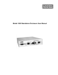
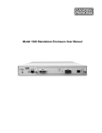
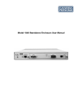
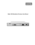
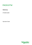
Model 1020 Standalone Enclosure User Manual
NOTICE!
This device contains static sensitive components. It should be handled only with proper Electrostatic
Discharge (ESD) grounding procedures.
NOTE!
Cet équipement contient des composants sensibles aux décharges électro-statiques. Il doit absolument
être manipulé en respectant les règles de mise à la terre afin de prévenir de telles décharges.
NOTICE
Canoga Perkins has prepared this users manual for use by customers and Canoga Perkins personnel as
a guide for the proper installation, operation and/or maintenance of Canoga Perkins equipment. The
drawings, specifications and information contained in this document are the property of Canoga
Perkins and any unauthorized use or disclosure of such drawings, specifications and information is
prohibited.
Canoga Perkins reserves the right to change or update the contents of this manual and to change the
specifications of its products at any time without prior notification. Every effort has been made to
keep the information in this document current and accurate as of the date of publication or revision.
However, no guarantee is given or implied that the document is error free or that is accurate with
regard to any specification.
Canoga Perkins Corporation
20600 Prairie Street
Chatsworth, California 91311-6008
Business Phone: (818) 718-6300
(Monday - Friday 7 a.m. - 5 p.m. Pacific Time)
FAX: (818) 718-6312 (24 hrs.)
Web Site: www.canoga.com
Email: [email protected]
Copyright© 2003-2005 Canoga Perkins Corporation
All Rights Reserved
EdgeAccess® Universal Chassis System
Model 1020
Users Manual
Model Number 1020-UM
Product Number 6913070
Rev. D 01/2008
2
EdgeAccess Model 1020
Model 1020 Standalone Enclosure User Manual
The Model 1020 standalone enclosure, shown in Figure 1, supports one 2U-sized module that is
managed through either SNMP or Sideband Management Control (SBMC).
Figure 1. Model 1020 Standalone Enclosure
The front provides three switches, three LEDs, two connectors, and a slot for a managed module. The
back includes an AC power cord socket. The AC power supply provides +5 VDC to the module.
Switch
Setting
MDM/TRM for EIA-232 port
Selects
MDM
DTE terminal for SLIP
TRM
DCE terminal for VT100
F1/NRM/F2, typically for Loopback for the module
F1
Local loopback, typically
Note:
NRM
Normal operation
F2
Remote loopback, typically
HDX
Half duplex
FDX
Full duplex
Set to NRM except to isolate a fault.
HDX/FDX for 10BASE-T port
Note:
If the link partner is set to auto-negotiation, the link uses 10M and follows the HDX/FDX
switch setting for this port; otherwise, set this switch to match the other switch on the link.
LED
PWR
Tx for 10BASE-T port
LNK/Rx for 10BASE-T port
State
Definition
Off
No power
Green
Power is on
Off
No transmission
Green blinking
Transmission activity
Off
No link
Green
Link is established at full duplex
Amber
Link is established at half duplex
Blinking
Data is received
EdgeAccess Model 1020
3
Connector
EIA-232
Manages
Serial port for modem or terminal
10BASE-T Half or full duplex Ethernet; supports only modules that include SNMP,
such as 2x46 or L3x1
Installing and Using the 1020 Enclosure
To use the 1020 enclosure:
1. Place it on a secure surface with room for air flow and within 10 ft. (3 m) of the AC power
source.
2. Insert a managed module in the guide rails and press it firmly into the backplane, then secure the
thumbscrew finger-tight.
3. Plug the power cord into the rear of the 1020 enclosure, then plug it into the AC power source;
this turns on the power. To turn off the power, unplug the power cord.
4. To set any switches on the module, install the module in the 1020 enclosure, connect all cables,
and access the module, see the User Manual for the module.
Use HyperTerminal for your first VT100 session. These steps briefly describe how to set up your PC
for a terminal connection. For details on using Windows, see your Windows documentation.
1. Turn on your PC.
2. When the Windows desktop appears, click Start, then highlight Programs, Accessories, the
HyperTerminal Folder, and then click HyperTerminal.
3. At the Connection Description dialog, select an icon, enter a name for the connection to the
system, and click OK.
4. At the Connect To dialog, pull down the Connect using menu, select the COM port, and
click OK.
5. At the COM Properties dialog, on the Port Settings tab, check for these selections:
•
•
•
•
•
Bits per second: 19200 bps
Data bits: 8
Parity: None
Stop bits: 1
Flow control: None
6. Click OK. HyperTerminal connects to the system and the VT100 terminal emulation starts.
7. To use the module and access its management functions in the 1020 enclosure, see the User
Manual for the module.
4
EdgeAccess Model 1020
Specifications
Dimensions:
10.0"L x 6.25"W x 1.625"H (254 mm x 159 mm x 43 mm)
Weight:
3.0 lbs (1.4 kg)
Power:
10 W maximum
100 to 240 VAC; 50 to 60 Hz autoranging
Operating Environment: 0° to +50°C
Up to 90% (Non-condensing)
Regulatory Compliance
•
•
•
•
•
•
ETL, cETL (UL 60950 CAN/CSA C22.2 No. 60950, EN/IEC 60950) EN 60825-1, -2,
CDRH CFR21
FCC Part 15B/IC-003/VCCI Class A, C-Tick (AS/NZS 3548)
EN 55022 Class A, EN 61000-3-2, EN 61000-3-3
EN 55024
R&TTE Directive (EN 300 386)
CE Mark
Warranty Information
Current Warranty information is available on-line in the Client Login Area of the Canoga Perkins
web site (www.canoga.com) or by contacting Technical Support at 800-360-6642 (voice) or
[email protected] (email).
EdgeAccess Model 1020
5
6
EdgeAccess Model 1020