1
Mar / 03
VERSION 2
C D 6 0 0 M E
smar
www.smar.com
Specifications and information are subject to change without notice.
Up-to-date address information is available on our website.
web: www.smar.com/contactus.asp
Introduction
INTRODUCTION
The CD600 Multi-Loop Digital Controller is a stand alone control station which combines the reliability of
single loop control with the flexibility, loop coordination and economy of Multi-Loop control.
For the design engineer, the CD600 offers the function block concept, that combines in the same block
several related functions. These function blocks provide all the computational and control functions
needed for advanced control strategies but yet are very easy to use. A wide variety of preconfigured
control strategies are also available in plug-in memories for the hand held terminal. New control
strategies are very easy to implement.
For the operating personnel the CD600 offers na user friendly control panel with individual push
buttons, an eight-digit alphanumeric display and a reliable hardware. If the controller must be
reconfigured or if an unlikely Fault occurs, the controller outputs are automatically switched to the
independent backup station.
And for the plant management, the CD600 offers cost effective modularity. Management information
through digital communication and plant integration through CRT based operator station.
III
CD600- User's Manual
IV
Table of Contents
TABLE OF CONTENTS
SECTION 1 - OPERATION.................................................................................................................................. 1.1
FRONT PANEL OF THE CD600 .........................................................................................................................................1.1
DESCRIPTION OF THE FRONT PANEL ...........................................................................................................................1.1
BARGRAPHS DESCRIPTON............................................................................................................................................................1.1
LOOP SELETION................................................................................................................................................................1.2
ALARM ACKOWLEDGEMENT ...........................................................................................................................................1.2
BACKUP STATION .............................................................................................................................................................1.4
SECTION 2 - TUNING ......................................................................................................................................... 2.1
SECTION 3 - PROGRAMMING ........................................................................................................................... 3.1
INTRODUCTION .................................................................................................................................................................3.1
DOWNLOAD MODE..........................................................................................................................................................3.22
OPERATION MODE..........................................................................................................................................................3.23
BLOCK ADJUSTMENT/CHARACTERIZATION ...............................................................................................................3.26
BLOCK MONITORING ......................................................................................................................................................3.28
UTILITY MODE..................................................................................................................................................................3.30
VS - SOFTWARE VERSION .............................................................................................................................................3.32
SECTION 4 - LIBRARY OF FUNCTION BLOCKS ............................................................................................. 4.1
FUNCTION TABLE..............................................................................................................................................................4.1
FUNCTION 01 - ANALOG INPUT (AI) ................................................................................................................................4.2
OPERATION......................................................................................................................................................................................4.2
FUNCTION 02 - CURRENT OUTPUT (CO) .......................................................................................................................4.3
OPERATION......................................................................................................................................................................................4.3
FUNCTION 03 - VOLTAGE OUTPUT (VO) ........................................................................................................................4.4
OPERATION......................................................................................................................................................................................4.4
FUNCTION 04 - DIGITAL INPUT (DI).................................................................................................................................4.5
OPERATION......................................................................................................................................................................................4.5
FUNCTION 05 - DIGITAL OUTPUT (DO) ...........................................................................................................................4.6
OPERATION......................................................................................................................................................................................4.6
FUNCTION 06 - FRONT VIEW (FV) ...................................................................................................................................4.7
OPERATION......................................................................................................................................................................................4.7
FUNCTION 07 - LOCAL/REMOTE SP SELECTOR (L/R) ..................................................................................................4.9
OPERATION......................................................................................................................................................................................4.9
FUNCTION 08 - AUTOMATIC/MANUAL STATION (A/M) ................................................................................................4.12
OPERATION....................................................................................................................................................................................4.12
FUNCTION 09 - ADVANCED PID (PID) ...........................................................................................................................4.16
INTRODUCTION .............................................................................................................................................................................4.16
DEFAULT ..........................................................................................................................................................................4.29
FUNCTION 11 - STEP CONTROLLER (TEP) ..................................................................................................................4.30
OPERATION....................................................................................................................................................................................4.30
FUNCTION 12 - MULTIPLIER-DIVIDER-ADDER-SUBTRACTOR (ARTH) .....................................................................4.34
OPERATION....................................................................................................................................................................................4.34
FUNCTION 13 - SQUARE ROOT (SQR)..........................................................................................................................4.39
OPERATION....................................................................................................................................................................................4.39
FUNCTION 14 - LINEARIZATION (LIN) ...........................................................................................................................4.40
OPERATION....................................................................................................................................................................................4.40
FUNCTION 15 - DERIVATIVE/LEAD-LAG (LL) ................................................................................................................4.42
OPERATION....................................................................................................................................................................................4.42
FUNCTION 16 - PRESSURE AND TEMPERATURE COMPENSATION (PTC)..............................................................4.46
OPERATION....................................................................................................................................................................................4.46
FUNCTION 17 - POLYNOMIAL (POL)..............................................................................................................................4.50
OPERATION....................................................................................................................................................................................4.50
FUNCTION 18 - TOTALIZATION (TOT) ..........................................................................................................................4.52
OPERATION....................................................................................................................................................................................4.52
V
CD600- User's Manual
FUNCTION 19 - PULSE TOTALIZATION INPUT (P/DI)...................................................................................................4.54
OPERATION....................................................................................................................................................................................4.54
FUNCTION 20 - BATCH COMPARATOR (BAT) ..............................................................................................................4.59
OPERATION....................................................................................................................................................................................4.59
FUNCTION 21 - SETPOINT GENERATOR (SPG)...........................................................................................................4.61
OPERATION....................................................................................................................................................................................4.61
FUNCTION 22 - DOUBLE ALARM (ALM).........................................................................................................................4.63
OPERATION....................................................................................................................................................................................4.63
FUNCTION 23 - LIMITER WITH ALARM (LIMT) ..............................................................................................................4.65
OPERATION....................................................................................................................................................................................4.65
FUNCTION 24 - LOGIC (LOG)..........................................................................................................................................4.69
OPERATION....................................................................................................................................................................................4.69
FUNCTION 25 - TIMER (TMR) .........................................................................................................................................4.71
OPERATION....................................................................................................................................................................................4.71
FUNCTION 26 - HIGH/LOW SELECTOR (H/L) ................................................................................................................4.72
OPERATION....................................................................................................................................................................................4.72
FUNCTION 27 - INTERNAL/EXTERNAL SELECTOR (SSEL).........................................................................................4.73
OPERATION....................................................................................................................................................................................4.73
FUNCTION 28 - CONSTANT ADJUSTER (ADJ)..............................................................................................................4.73
OPERATION....................................................................................................................................................................................4.74
FUNCTION 29 - INPUT SELECTOR (ISEL) .....................................................................................................................4.76
OPERATION....................................................................................................................................................................................4.76
FUNCTION 30 - OUTPUT SELECTOR (OSEL) ...............................................................................................................4.78
OPERATION....................................................................................................................................................................................4.78
FUNCTION 31 - LINEARIZATION CURVE (PNT) .............................................................................................................480
OPERATION....................................................................................................................................................................................4.80
FUNCTION 32 - GENERAL VISUALIZATION (GV)..........................................................................................................4.84
OPERATION....................................................................................................................................................................................4.84
FUNCTION 33 - CONSTANTS (K)....................................................................................................................................4.85
OPERATION....................................................................................................................................................................................4.85
FUNCTION 34 - SCAN (SCN)...........................................................................................................................................4.86
OPERATION....................................................................................................................................................................................4.86
FUNCTION 35 - SCAN/ACTUATION OF THE PARAMETERS PID (PRM) .....................................................................4.89
OPERATION....................................................................................................................................................................................4.89
FUNCTION 36 - ACTUATION (ATU) ................................................................................................................................4.91
OPERATION....................................................................................................................................................................................4.91
SECTION 5 - RESIDENT CONFIGURATION...................................................................................................... 5.1
SECTION 6 - TECHNICAL SPECIFICATIONS ................................................................................................... 6.1
POWER SUPPLY AND CONSUMPTION ...........................................................................................................................6.1
VOLTAGE............................................................................................................................................................................6.1
CONNECTION DIAGRAMS...............................................................................................................................................................6.6
ORDERING CODE..............................................................................................................................................................6.8
SECTION 7 - CALIBRATION .............................................................................................................................. 7.1
ANALOG INPUT (AI) ...........................................................................................................................................................7.1
SECTION 8 - COMMUNICATION........................................................................................................................ 8.1
INTRODUCTION .................................................................................................................................................................8.1
CONTROLLER ADDRESSING ...........................................................................................................................................8.1
BAUD RATE ......................................................................................................................................................................................8.2
CYCLE TIME ADJUSTMENT..............................................................................................................................................8.3
INTRODUCTION ...............................................................................................................................................................................8.3
SECTION 9 - INSTALLATION............................................................................................................................. 9.1
INITIAL INSPECTION .........................................................................................................................................................9.1
POWER SUPPLY................................................................................................................................................................9.1
EQUIPMENT INSTALLATION.............................................................................................................................................9.2
PANEL LAYOUT .................................................................................................................................................................9.2
VI
Table of Contents
WIRING ...............................................................................................................................................................................9.3
COMMUNICATION .............................................................................................................................................................9.5
SIGNAL CABLES INTERCONNECTION ............................................................................................................................9.6
TRANSPORTATION AND STORAGE ................................................................................................................................9.8
APPENDIX A – SRF – SERVICE REQUEST FORM ..........................................................................................A.1
APPENDIX B – SMAR WARRANTY CERTIFICATE ..........................................................................................B.1
VII
CD600- User's Manual
VIII
Section 1
OPERATION
Front Panel of the CD600
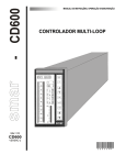
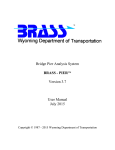
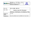
The front panel of the CD600 (Figure 1.1) consists of three bars of LEDs, an alphanumeric display,
a group of Keys for adjustment and control, and signaling LEDs.
Description of the Front Panel
Bargraphs Descripton
SP - Indication of monitored loop's Setpoint it is indicated on the green 101 LEDs bargraph.
PV - Indication of the monitored loop's Process Variable. It is indicated on the red 101 LED's
bargraph.
MV - Indication of the monitored loop's Manipulated Variable. It is indicated on the red 41 LEDs
bargraph
Since the visualization of each loop can be freely configured by the user. The three bargraphs may
also be used for other purposes.
Fig 1.1 - Front Panel
1.1
CD600- User's Manual
KEYS
DESCRIPTION
Selects the variable to be shown in the alphanumeric display.
Selects the loop to be monitored on the front panel.
Increases the value of the variable shown on the display.
Decreases the value of the variable shown on the display.
Selects the Local Setpoint or the remote Setpoint of the monitored loop.
Alarm Acknowledgement
Selects the Automatic or Manual mode of the monitored Loop.
Increases the MV value, when the control is in Manual. When touched shows the
output value on the display.
Decreases the MV value, when the control is in Manual. When touched shows the
output value on the display.
When lit, indicates that the controller is in fault condition.
Blinks every 10 cycles, during cycle time adjustment (refer to section 8
communication).
When lit, indicates that the variable, which is being shown on the display can have
its value changed by the keys <Δ> and <∇>.
1, 2, 3 or 4 - When lit, indicates that the variables, shown on the front panel refer
to the respective Loop.
L - When lit, indicates that the respective Loop is working with Local Setpoint. L
unlit means Remote Setpoint.
M - When lit, indicates that the respective Loop is working in the Manual mode. M
unlit means Automatic Operation.
or
- When lit, indicates an alarm situation.
Loop Seletion
A short touch on the <LP> key lets the display show the Tag (see below) of the loop being
monitored. A longer touch transfers the monitoring to the next Loop. Initially, the new Loop's Tag is
show and, after a few seconds, the monitored information.
Alarm Ackowledgement
Independently of the Loop selected and of the variable, being shown on the display, if any alarm,
which has been programmed to be indicated on the front panel, occurs, the display goes on to
show the information of the variable and the "*ALARM" information alternately. Furthermore, one
of the LED's < > or < > from the respective loop, blinks.
As soon as the operator presses the <ACK> key for the first time, the Tag, which identifies the
configuration, appears on the display, followed by the mnemonic message of the alarm. The
message will blink until the operator presses the <ACK> Key again, acknowledging the alarm. After
acknowledgement, the message stops blinking and remains displayed if the alarm condition
persists. Otherwise, will be displayed the next alarm of the stack or the "NO ALARM" message, if
no alarm exists.
The alarm acknowledgement can also be made automatically. It means that when an alarm
condition disappears, the message also disappears, without the acknowledgment by the <ACK>
key.
1.2
CD600- Operation
While the alarm is present, the alarm message remains stored in memory stack with capacity for
up to 36 alarm messages.
With the keys <Δ> and <∇>, the operator can scroll the stack, checking whether there are other
alarms present or not.
Among the alarm messages, which can be visualized on the display, the user can write eight, and
the remainders are fixed messages. The blocks that can provide these alarms, and its
characteristics, are listed in table 1.1.
BLOCK
TYPE
DEFAULT
MNEMONIC
CONFIGURABLE
MNEMONIC
001
BURNOUT
AI1 OUT
NO
002
BURNOUT
AI2 OUT
NO
003
BURNOUT
AI3 OUT
NO
004
BURNOUT
AI4 OUT
NO
005
BURNOUT
AI5 OUT
NO
006
BURNOUT
AI6 OUT
NO
007
BURNOUT
AI7 OUT
NO
008
DEV/BURNOUT
AI8 OUT
NO
009
DEV/BURNOUT
A01 OUT
NO
010
DEV/BURNOUT
AO2 OUT
NO
011
DEV/BURNOUT
AO3 OUT
NO
012
DEV/BURNOUT
AO4 OUT
NO
039
DEVIATION
DEV - 1
NO
040
DEVIATION
DEV - 2
NO
041
DEVIATION
DEV - 3
NO
042
DEVIATION
DEV - 4
NO
077 (1st comp)
LOW/EQUAL/HIGH
LOW COMP
YES
nd
077 (2 comp)
LOW/EQUAL/HIGH
HGH COMP
YES
078 (1st comp)
LOW/EQUAL/HIGH
LOW COMP
YES
078 (2nd comp)
LOW/EQUAL/HIGH
HGH COMP
YES
079 (1st comp)
LOW/EQUAL/HIGH
LOW COMP
YES
079 (2nd comp)
LOW/EQUAL/HIGH
HGH COMP
YES
080 (1st comp)
LOW/EQUAL/HIGH
LOW COMP
YES
080 (2nd comp)
LOW/EQUAL/HIGH
HGH COMP
YES
081
UPPER LIMIT
LIM H 01
NO
081
LOWER LIMIT
LIM L 01
NO
081
SPEED
VELOC 01
NO
082
UPPER LIMIT
LIM H 02
NO
082
LOWER LIMIT
LIM L 02
NO
082
SPEED
VELOC 02
NO
083
UPPER LIMIT
LIM H 03
NO
083
LOWER LIMIT
LIM L 03
NO
084
SPEED
VELOC 03
NO
085
UPPER LIMIT
LIM H 04
NO
085
LOWER LIMIT
LIM L 04
NO
085
SPEED
VELOC 04
NO
Table 1.1 - Alarm Characteristics
1.3
CD600- User's Manual
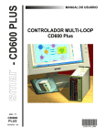
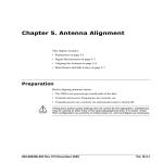
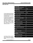
Backup Station
Optionally, the CD600 controller can have a backup station, whose main function is to guarantee
the current signals to the final control elements connected to the controller. By pressing the lock
spring on the lower part of the front frame and pulling it until the second lock, the operator has
access to the backup station (Figure 1.2). This backup can take on the current signals in two
distinct situations:
1.
MANUALLY - By positioning the <AUTO/BACKUP> switch in the "BACKUP" position, the
operator can adjust the four current outputs independently by means of the respective adjustment
knobs. When the output current reaches the value adjusted on the knob (with a ±2.5% capturing
band) the LED located close to the current is being sent to the final control element.
2.
AUTOMATICALLY - With the <AUTO/BACKUP> switch in the "AUTO" position, a power supply
fault in the controller, or a fault of the Processing Unit (CPU) switches the command to the
backup station. Each one of the four current signals can remain at the last value generated by the
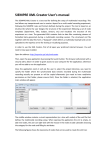
controller or go to the value adjusted on the respective knob. Definition of the switching mode is
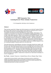
made independently for each output by means of DIP switches on the lower part of the GLL 660
board (Figure 1.3)
OFF Position - Output freezes at the last value generated by the controller.
ON Position - Output ramp up or down to the value adjusted on the respective knob.
Access to the DIP switches is obtained by removing the front panel of the backup (Figure 1.2). If
the safety position (ON) is chosen, when switching to the backup takes place, the output goes to
the adjusted value at a rate of 10%/second. After the current equalizes with the knob adjustment,
the respective LED lights up; from the on the operator can adjust the output with the knob.
If the backup is configured to "freeze" (OFF Position), when the output switches to the backup
station, it freezes in the last controller output value. In order to adjust the output with the knob, the
operator “finds” the frozen value by rotating the knob until the LED lights up. From now on the
output follows the value adjusted on the Knob.
Note
Should any main board's fault occur when the output is out of the potentiometer actuation range
(3.6 mA > output > 20.4 mA), it is necessary to switch the controller to backup, setting the DIP
switch (on the lower part of the GLL 660 board - Figure 1.3) to ON position.
From top to bottom, the knobs correspond to the outputs available at the terminals 6B, 7B, 8B and
9B on the rear panel of the CD600.
Fig. 1.2 - The Backup Station
1.4
CD600- Operation
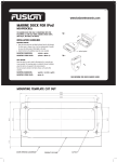
Furthermore, when the controller is out-of-order, the backup station also defines the states of the
first four digital outputs (terminals 3A, 4A, 5A and 6A). The state of these outputs, in case of
transferring to the backup station, is defined by four DIP switches existing on the upper part of the
GLL 660 board, see Figure 1.3.
ON Position - output open (output transistor cutoff).
OFF Position - output closed (output transistor conducting).
Fig. 1.3 - Dip Switches on GLL 660 Backup Station Board
1.5
CD600- User's Manual
1.6
Section 2
TUNING
Proportional gain, Integral time and Derivative time constants of any Proportional, Integral,
Derivative (PID) block existing in the controller's configuration may be adjusted from the front
panel without using the Programmer. To make it possible, it is necessary to set the CACT
parameter, of the respective PID block, to "0" or "1".
In order to use the front panel, the key <NORM/CONF> on the right of the programmer
connecting jack, switches the display and the two adjustment keys <Δ>, <∇> from normal
operation to tuning mode and vice-versa. Independently of the variable which was being
shown previously, the display goes on to indicate the value of the proportional constant of the
PID, of the selected Loop. If there is more than one PID Block in the Loop (Cascade Control,
for example), the proportional gain referring to the smallest PID block number appears on the
display first. In this case, the user should know the blocks which comprise the Loop, in order to
identify which one is the "master" and which one is the "slave".
The mnemonic of each constant consists of two letters, which identify the type of action, and
one number which identifies the PID Block.
KP: Proportional Gain
TR: Integral (Reset) Time (min/rep.)
TD: Derivative Time (min)
1
BLK039
1st
2
BLK040
2nd
3
BLK041
3rd
4
BLK042
4th
5
BLK043
1st
6
BLK044
2nd
7
BLK045
3rd
8
BLK046
4th
Advanced PID
Simple PID
Table 2.1 - PID Block corresponding number for front panel Tuning
When the existing configuration has more than one Loop, the key <LP> is used to change
the Loop and to obtain its PID parameters.
By means of the <Δ>, <∇> keys, the PID constants can be adjusted as long as the
<SAFE/NVRAM> switch is in "NVRAM" position. The scroll of all tuning parameters of all
the PID blocks of a Loop is made by the <DSP> key.
The front panel Keys (DSP, Δ, ∇, ACK) return to their normal functions by pressing the key
<NORM/CONF> or in 20 seconds, if any key frontal panel is not actuated.
Notes:
a) Using the SMAR Hand-Held Terminal in OPERATION mode (Section 3) it is also
possible to tune the controller.
2.1
CD600- User's Manual
b) Tuning by front panel can be inhibited by the configuration or by positioning the
<SAFE/NVRAM> switch in "SAFE" position.
c) Tuning can also be done through a computer connected to the communication port or
to the jack used for the Hand-Held Terminal.
2.2
Section 3
PROGRAMMING
Introduction
The programming of the SMAR CD600 Digital Controller is based on the concept of freely
interconnectable Function Blocks. The interconnection is done in accordance to the control
strategy defined by the user.
All the function blocks already exist in a part of the memory not accessible by the user.
Programming the controller means to configure it by calling the necessary blocks into the user
memory, NVRAM, link them together, set their Characterization and Adjustment parameters to fit
a specific application.
Exchange of information between the used control algorithm and the process is done by means of
the input and output Function Blocks (both analog and digital). By these blocks the programmed
configuration is "physically" connected to the controller terminal block. Therefore, for example, the
Analog Input block No.1 can only be used for reading and processing the signal which is connected
to the terminal 18A (first analog input).
TYPICAL DESCRIPTION OF A BLOCK
The blocks described in Section 4 have a Control Function, consisting of one or more
mathematical and/ or logical operations. The function will relate block inputs with block outputs. The
inputs are designated by letters (A, B, C...), and outputs are designated by numbers. Exceptions are
the Analog and Digital input and output blocks, whose inputs, respectively outputs, are related to
hardwired terminals.
A
B
HIGH
139/141
143/145
LOW
140/142
144/146
HIGH
LOW
SELECTOR
C
ANALOG
INPUTS
D
DISCRETE INPUTS
Fig 3A - Typical Block
The numbers related to the block outputs are addresses. Each number refers exclusively to a
certain output of a certain block and vice versa.
Each block has one Linking Parameter (L) for each input. A block with three inputs has the Linking
Parameters LIA, LIB, and LIC (Link Input A, B and C). If the HIGH-LOW selector block shown in
Figure 3A has LIA=2, that means that the input A of that block is on.
As a block can perform several operations, the activations of these operations are defined by the
Characterization Parameters. For example, the Analog Input block offers a choice of
implementing SQuare Root extraction (CSQR=1) or not (CSQR=0). It offers also a choice to use
LINearization (CLIN=1) or not (CLIN=0) - (See Figure 3B).
Constants in the Function Blocks that require frequent changes during process operation are called
Adjustment Parameters (A Parameters). The same Analog Input block has an adjustable filter,
which has a time constant adjustable by ATIM.
3.1
CD600- User's Manual
There are two types of signals between blocks: scalar and discrete. Scalar are continuous signals
while discrete are on-off type of signals.
The signal transfer through block links is always made in the form of percentage, even if the signal is
discrete (0% for low logical level 0 and 100% for high logic level 1). A scalar signal, connected to an
input prepared to receive discrete signals, will be interpreted as follows:
- less than 70%:
- more than 80%:
- between 70% and 80%:
level 0
level 1
previous state
The output signal of a block can be received by as many inputs of blocks as desired.
THE LOOPS
A Loop is a set of interconnected blocks with a certain purpose. It has a single man-machine
interface for the manipulation and visualization of data by the front panel of the controller. The
maximum number of loops per CD600 is four.
The CD600's program also offers a configuration workspace named General Loop, "LOOP G"
which contains only blocks that may be simultaneously used by more than one loop. An example of
information maintained in the General Loop are the coordinates of the points used by a linearization
curve that may be used by several Analog Inputs simultaneously.
The Tag (Loop identification, see below) of the General Loop will always be the Tag of the whole
configuration. All configurations must have a General Loop, even if the program contains only one
control Loop. If no blocks are configured for the General Loop, at least a Tag must be given.
3.2
3.25
CD600 - Programming
Fig. 3.B - Example of a Function Block
3.3
CD600- User's Manual
TAG
The Tag is the identification which must be given to each control Loop, as well as to the General
Loop. It consists of up to 8 alphanumeric characters, for example:
FIC100, LI200, TIC00102, ...
The General Loop TAG is an identification of the controller, that may have up to 4 loops. The TAG
can be the controller number, a name for the functions performed by the four loops or any other
identification.
HOW TO PROGRAM THE CD600
When the CD600 is delivered from the factory it already has a configuration called "4 loops" - see
Section 5. This configuration may be changed to suit a particular application or replaced by a new
configuration.
A program can be made, changed or have its parameters modified through a PC type computer or
through the Hand-Held Terminal.
The PC type will require an appropriate interface and the software CONF600. More details are given
in the CONF600 manual.
The programming with the Hand-Held Terminal is described in the following sections. The
CONF600 software is a powerful graphical user interface using a mouse on the computer keyboard
and menu type of data entry. The CONF600 can also run on a portable laptop or palmtop and can
also be brought into the field as long as the hardware allows. Configuration is done by drawing the
control blocks and their links, much in the same way as a control diagram or a wiring diagram on a
CAD SYSTEM. Help windows provide parameter explanations, options and ranges. The CONF600
also works on-line with up to 29 CD600 giving continuously access to all parameters and
input/output monitoring of all blocks, facilitating troubleshooting of configurations. The CONF600
package also provides for documention with hard copies of the configurations, configuration storage
on disc and optionally, data transfer to, and from the HHT.
THE HAND-HELD TERMINAL
The configuration for the control to be performed by the CD600 controller is prepared off-line with the
SMAR Hand-Held Terminal (Figure 3.2).
The Hand-Held Terminal is powered by a 9V PP3 size battery or by a 9 Vdc external power supply
(when it is not communicating with the controller) - see specifications on Section 6 - Technical
Specifications - which can be connected to the jack located in the communication interface (See
Figure 3.1). The Hand-Held Terminal can also be supplied directly by the controller, if:
a) The main board GLL600 is revision 3 or higher.
b) The communication interface has a Serial Number followed by an "A" letter (e.g.: Serial Number
01166A).
Any 9 volts "Power Pack" battery may be used. However, for longer operating life, alkaline batteries are
recommended. After removal of the protective cover by pulling it downwards, insert the battery,
observing the polarity (see Figure 3.2).
3.4
3.3
CD600 - Programming
Fig 3.1 - Smar Hand-Held Terminal
Fig 3.2 - Battery Case
The SMAR Hand-Held Terminal has a three-mode keyboard with double function keys. The initial
mode is the alpha-uppercase mode. Switching from this mode to the alpha-lowercase or to the
numeric mode is effected by pressing <SHIFT> and simultaneously <CAP> or <NUM>, respectively.
To return, repeat the combination. The name of a respective function or character is indicated upon
and above the keys. Keys with an operational function on the keyboard are described as follows:
Used to switch on the Hand-Held Terminal. The display will show the menu, the
list of available applications. It is also used to retrieve to the previous menu.
If the display is not easily readable, adjust the contrast. See Figure 3.1 to locate
the contrast adjustment.
Used to switch on the Hand-Held Terminal. The display will show the menu, the
list of available applications. It is also used to retrieve to the previous menu.
Used to access the symbols and numbers indicated above the respective keys.
When the programmer is in an alpha mode, this key should be pressed
simultaneously with the desired symbol or number key. In the numeric mode, the
alpha characters are reached instead of the numbers
Used to erase characters which have been pressed by mistake.
Used to insert a blank space
Used to call a new Function Block in the Program CD600 or to order a change in
a Linking, Characterization or Adjustment Parameter while the old value
appears on the display. Used also to confirm an action.
TO SWITCH THE HAND-HELD TERMINAL OFF, select option "OFF" from the Opening Menu, using
the cursor keys and the <EXE> key, or by pressing key <0>. If the Hand-Held Terminal remains
connected without any key having been pressed during a period of five minutes, it will switch itself Off
automatically.
3.5
CD600- User's Manual
TO TURN THE HAND-HELD TERMINAL ON, PRESS
* TO TURN OFF, MOVE THE CURSOR TO OFF AND
PRESS
OR PRESS
CD600
EXE
OR
OFF
C
EXE
OR
0
ON
TURNS THE
HHT OFF
PRG
DWL
OPR
UTL
Fig 3.3 - Switching the Hand-Held Terminal On and Off
The SMAR Hand-Held Terminal is, actually, a Microcomputer (Figure 3.1) which, at the user's
request, performs the execution of a program called "CD600", described in Section 3. This program is
used to develop the control configurations for the CD600 and to make the microcomputer "talk" with the
CD600. The program is contained in a "Program-Pack", which must be inserted in slot "B". See Figure
3.1.
When the <EXE> key is pressed, the program is transferred from the Program Pack to the
microcomputer's operational memory (Random Access Memory - RAM, device "A").
A second slot (slot device "C") is prepared for the "Datapack" or "RAMPACK" that contains or can
store control configurations prepared by the user or preconfigured by SMAR.
The "Datapack" is a EPROM memory, thus it needs a EPROM Eraser to erase it.
The "RAMPACK" is a Nonvolatile Memory (NVRAM), but the Hand-Held Terminal can be used to
erase it. It can be done using the FMT option from the Utility (UTL) mode. Be sure not to connect or
disconnect the "RAMPACK" while the Hand-Held Terminal is on.
The Hand-Held Terminal also has an Interface used to communicate with the controller for writing or
reading data.
Configurations stored in the controller or in a Data-Pack are protected against changes by unauthorized
personnel by several Passwords. There is one for each type of operation. See UTILITY MODE in
Section 3.
3.6
3.5
CD600 - Programming
HAND - HELD TERMINAL
SLOT B
DISPLAY
CD600
CPU
SLOT C
NVRAM
RAM
DEVICE
COMMUNICATION
INTERFACE
Fig 3.4 - Block Diagram of the SMAR Hand-Held Terminal
In the CD600 controller, a configuration received from the Hand-Held Terminal is stored in a
nonvolatile RAM memory, "NVRAM", which can be rewritten according to the user's requirements.
The SMAR Hand-Held Terminal can also be used to communicate with transmitters from the SMAR
Intelligent Transmitter Series 300 and 301. To do so, just replace the Program-Pack containing the
Program CD600 in slot "B" by the respective transmitter's Program-Pack. For series 301 a HART
protocol interface and a 4 line HHT are required.
THE PROGRAM CD600
When executing the CD600 program in the Hand-Held Terminal, the user can use one of the four
different modes, selected from the main menu:
PROGRAMMING MODE (PRG): Used for creating configurations which, when finished, checked and
compiled, can be downloaded into the CD600 controllers or into a Datapack in slot "C".
DOWNLOAD MODE (DWL): Used to transfer one of the configurations stored in the Data-Pack of slot
"C" to the controller.
OPERATION MODE (OPR): In this mode, the user can access any part of the configuration existing in
the controller, which allows the user to monitor the output signal of any Function Block and the signals
at the terminals of any "physical" input or output block. It is also possible to change the
Characterization and Adjustment Parameters of these blocks. Both monitoring, as well as eventual
changes, are made "on-line".
UTILITY MODE (UTL): This mode allows the user to know the software version and the memory not
yet used in the current Datapack. It allows also to compiling, copying and deletion of existing
configurations. Several programmer functions can be tested.
In this mode the passwords (access codes) of each hierarchical level and the assignments of the
respective levels to each mode are defined. There are three password levels:
Level 1
Level 2
Level 3
Where, Level 1 surpasses Level 2, and Level 2 surpasses Level 3.
Therefore, the Level 1 password is also accepted as password for Levels 2 and 3; the Level 2
password also attends Level 3, but does not attend Level 1. The Level 3 password only attends its own
level.
The modes PRG, DWL and UTL have one password, each, and OPR has two passwords. Their
hierarchical classification enables the user to have a division of tasks and responsibilities in his team.
3.7
CD600- User's Manual
If hierarchization is not desired, the user may place all the modes at the same level, or else define all
the levels with the same password.
A hierarchical division of passwords could be made in the following way:
a) PRG Mode - Level 1 Password, since this mode is without any doubt the one which requires more
knowledge, both of the controller and of the process. A person who is qualified to develop
configurations should be qualified for any other task.
b) DWL Mode - Level 2 Password: does not demand much knowledge because it deals with
configurations already done and tested. It is recommended that the shift personnel which attends to
emergencies have access to this mode.
c)
OPR/ADJUSTMENT Mode - Level 3 Password: only enables changes of constant adjustments,
such as for alarm levels, filters, etc.
d) OPR/CHARACTERIZATION Mode: Level 2 Password, since it enables tasks of greater
responsibility, such as making use or not of the square root extraction from the process signal, etc.
e) UTL Mode - Level 1 Password: as it enables access to all the passwords and definition of levels by
mode. Since it is desired to hierarchize access to the various modes, only persons at the top of
hierarchy should have access to all the passwords.
The Downloading, Operation and Utility Modes are relatively simple to work with. After an analysis of
the respective Programming Trees (see Figure below) and a little practice with the Hand-Held
Terminal, the user will feel comfortable to work with them. The menus are almost self-explanatory.
The Programming Mode provides the user with enormous flexibility; he can create configurations for the
CD600 using his knowledge of the process and of the library of blocks. He can use configurations
stored in another controller or in the Datapack. The wide range of options, available to the user in this
mode, requires a more careful reading of the next section.
A simple analysis of the Programming Tree of the PRG mode (see below) is not sufficient for a good
understanding of this mode, therefore, in the following text, we are going to discuss this mode in more
details, explaining the concepts involved and showing a practical example of the development of a new
configuration.
CD600
OFF
EXE
ON
PRG
Programming:
Make or
modify a
program
DWL
OPR
Download:
Download a
program to
the controller
Operation:
- Monitor
- Modify
parameters
UTIL
Utility:
- Passwords
- Software version
- Compile
- Copy
- Delete
- Format
- Test
Fig 3.5 - Programming tree: Main menu
3.8
3.7
CD600 - Programming
THE PROGRAMMING MODE
A configuration for a CD600 controller may contain up to four control LOOPs. In addition to these four
LOOPs, the configuration must have a fifth LOOP, called LOOP G, containing the TAG (Identification)
of the whole configuration and the blocks whose information can be shared by more than one of the
control LOOPs.
Before starting to learn how to develop a configuration, it is necessary to understand the following
concepts:
BASE - The BASE is the starting point of the configuration to be created. It can be of three types:
NEW - There is no configuration to be used as a starting point. It is like to start a NEW drawing on a
blank sheet of paper.
ID - The starting point is one of the configurations found by its IDentification Tag in the Data-Pack
inserted in slot C:. This configuration will be transferred to the RAM memory, where it can have blocks
deleted or inserted, connections changed etc. It is like to copy a drawing and modify it accordingly.
CTR - The starting point is a configuration that is in a ConTRoller memory. This configuration will be
transferred to the RAM memory of the Hand-Held Terminal, where it can be changed.
DESTINATION
This is the place where the new configuration should be stored after checking. There are two possible
destinations:
CTR - In this case, the configuration is transferred to the NVRAM memory of the CD600 Controller.
ID - In this case, the configuration is stored in the Programmer's Datapack C:. In this option, the user
can store the configuration in the normal form (high level language) or in the compiled form (machine
language), that allows faster download of the configuration from the Datapack to the CD600 (DWL
mode) later on.
The Programming Tree of the Figure 3.6 show the commands to be used in the PRG mode.
In order to understand the example more easily, the main command keys and the situations in which
they are used in the PRG mode are listed below:
In the menu, calls the function indicated by the cursor. In the program, calls open
blocks (BLK000). In the program, inserts the block after a number is assigned to
it. Inside the block, calls and confirms alteration of parameters.
Returns the program to the previous level, i.e., from parameter to block, from block
to program tag, from configuration tag to menu.
3.9
CD600- User's Manual
THE PROGRAMMING MODE
LEVELS
PRG
EXE
ON
NEW
ID
CTR
EXE
LOOP G
ON
LOOP 2
LOOP 1
LOOP 3
LOOP 4
EXE
TAG
C
CXXX
ON
(CONF.)
CZZZ
CYYY
EXE
(TO CHANGE)
CHANGE
CONFIGURATION
PARAMETER
EXE
2) BLK YYY
1) BLK XXX
(TO ENTER
CHANGED
PARAMETER)
A
AXXX
(ADJ.)
L
AZZZ
AYYY
EXE
n) BLK ZZZ
(TO CHANGE)
CHANGE
ADJUST
PARAMETER
EXE
LXXX
(LINK)
LZZZ
LYYY
EXE
ON
(TO CHANGE)
CHANGE
LINK PARAMETER
(TO ENTER
CHANGED
PARAMETER)
EXE
(TO ENTER
CHANGED
PARAMETER)
Fig 3.6 - Programming Mode Tree
Used to call the checking mode.
Scrolls existing configurations in the Datapack to choose the configuration used as BASE.
Scrolls parameters of the same type (L, C or A).
Scrolls the blocks of a loop. Scrolls the LOOPs of a configuration.
Scrolls the configurations BASE.
Scrolls the configuration's DESTINATI-ON.
Accesses Linking Parameters of the block on the display.
Accesses Characterization Parameters of the block on the display.
Accesses Adjustment Parameters of the block on the display.
Allows the existing configuration in the Hand-Held Terminal's RAM to be compiled or
not, transferred to the controller or not, aborted or not, depending upon the option
prompted on the display.
3.10
3.9
CD600 - Programming
Figure 3.6 shows the hierarchical levels of a program. The <ON> key allows return to the previous
level. The <EXE> key moves to the next level. When working with the blocks, <EXE> will open new
blank blocks. After a number is given to a blank block, it can be inserted in the program with <EXE>.
The next section shows a program development step by step. Follow it!
EXAMPLE OF CONFIGURATION
The following control strategy shall be implemented in the CD600:
FLUID “A”
Q = 0-80Kg/s
A
FT
2
SP
PV
FIC
100
MV
FT
1
FCV1
Q = 0-20Kg/s
B
FLUID “B”
MIXTURE
Fig 3.7 - Desired Control Loop
Fluid B must be controlled in order to be equal to flow A. In section 4, function 12-ARTH, there is an
example where the ratio QA/QB is adjustable.
Before starting to work with the Hand-Held Terminal, it is recommended to draw the control
configuration, using the library of blocks as a reference. The drawing shall contain the block numbers
and the terminal numbers as shown in Figure 3.8.
The connections C and D of block 043 are explained in the block description. That is not important now.
Let us see how the program is developed and downloaded to the controller.
3.11
CD600- User's Manual
FT2
FT1
AI
001
AI
002
2
4
B
C
PID
043
D
A
55
A
A
A/M
035
40
B
FV
027
39
C
A
CO
009
FCV1
LIST OF BLOCKS
LOOP1
TAG:
1:
2:
3:
4:
5:
6:
FLOW
BLK 001
BLK 002
BLK 043
BLK 035
BLK 009
BLK 027
LOOP G
TAG: FIC 100
Fig 3.8 - Configuration of a Control Loop
The following commands, in the following sequence, shall be used to configure the controller.
The drawings show the keys pressed and the display afterwards.
ON
CD-600 OFF
EXE
LOANDING O.S.
PLEASE WAIT_
PRG DWL POR UTL
As the cursor is blinking under PRG, and Program Mode is desired:
EXE
PASSWORD:
_
C
D
6
0
0
EXE
SHIFT
NEW ID
BASE?
CTR
3.12
3.11
CD600 - Programming
We will start a new program, not yet available neither in the Data-Pack (ID) nor in the controller (CTR).
We choose NEW.
EXE
G
LOOP?
_
We have only one loop, but we must identify the controller. To do so, we must give to the General loop
an identifier (TAG):
EXE
TAG:
_
GN
We may name the controller FIC100
F
I
C
1
0
0
EXE
SHIFT
TAG:
FIC100
GN
GN on the right lower corner means General loop, NEW.
Now we must select one of the loops to place our configuration. We may select loop 1. In order to
return to the loop selection level we must press <ON> (see Figure 3.6).
ON
G FIC100
LOOP?
_
Select Loop 1.
↓
1
LOOP?
_
EXE
TAG:
_
1N
The message 1N in the lower right hand corner of the display informs that we are working on LOOP 1
and it is NEW.
Let's assume the TAG for LOOP 1 to be FLOW (an asterisk * in the upper right hand corner will
indicate that the tag is not entered yet.):
F
TAG:
FLOW
L
O
W
EXE
1N
3.13
CD600- User's Manual
To call the first block:
EXE
1)BLK000
1N
To enter block 001:
0
0
1
EXE
1)BLK001 I
ANLG.INP8/001 1N
The first line of the display informs that block BLK001 is inserted, [I] and that it is the first block of
the LOOP [1)].
The second line informs that this is a block type Analog Input (ANLG.INP) and that there are eight of
these blocks, being block BLK001 the first of them (8/001). In the right hand corner of the second line,
1N informs that this is LOOP 1, base NEW.
To call the second block:
EXE
2)BLK000
1N
To enter the second Analog Input.
0
0
2
EXE
2)BLK002 I
ANLG.INP8/001 1N
To call a new block and insert the PID block.
EXE
0
4
3
EXE
3)BLK043 I
PID CTR.4/043 1N
To call a new block and insert the fourth A/M station:
EXE
0
3
5
4)BLK035 I
A-M STA.4/035
EXE
1N
To call a new block and insert the current output:
EXE
0
0
9
EXE
5)BLK009 I
CUR.OUT.4/009 1N
3.14
3.13
CD600 - Programming
To call a new block and insert the Front View:
EXE
0
2
7
EXE
6)BLK027 I
FRT.VIEW4/027 1N
To delete a block inserted in the configuration by mistake, press the key <DEL>. When the block is
displayed.
In order to scroll the blocks of the Loop, use keys <↑ >, <↓>.
A block can be inserted in the Loop, between two blocks A and B, by scrolling the blocks up or down to
block A and then pressing <EXE> to insert a new block.
Important: If the same block is inserted in two different points of a configuration, an indication IX will
warn the user that the other block has been used in loop X. In our example, if we try to use
block BLK001 two times, for example the step 4 the display will show "4) BLK001 I1",
which means that BLK001 was already used in Loop 1.
Now we are ready to start linking the blocks. Only the inputs of blocks are linked. The outputs have
fixed addresses. In the DEFAULT condition all inputs have the address "0" (No connection). We may
start linking any block, at any time. For example, when entering the blocks, it is also possible to
configure the respective Linking Parameters.
Let's start at the beginning of the configuration by pressing:
↓
Or 6 times
↑
TAG:
FLOW
1N
↓
1)BLK001 I
ANLG.INP8/001 1N
This block has only one input and it is associated to the controller terminal 18A. If you try to link it by
pressing the <L> key, you will read the message:
1)BLK001
I
NOTHING TO CONFG
To go to the second block:
↓
2)BLK002 I
ANLG.INP8/001 1N
The input is associated to the terminal 17A (like in BLK001, there is nothing to link).
To go to the third block:
↓
3)BLK043
I
PID CTR.4/043
1N
3.15
CD600- User's Manual
L
LIA 0
INPUT A
043
The display indicates that the input A of block BLK043 has nothing connected. The block description
(Section 4) shows that input A shall receive the Setpoint, that comes from the second analog input,
block BLK002, output 4. In order to make the connection, you must ask to change by pressing:
EXE
LIA
0
_
Enter the Setpoint address (4):
4
LIA
0
4_
and confirm it
EXE
LIA
INPUT A
4
043
To move to input B, which is the Process Variable,
↓
LIB
0
INPUT
043
B
To change it to 2, which is the PV address, ask to change:
EXE
LIB
0
_
Enter 2 and confirm:
2
EXE
LIB 2
INPUT B
043
The PID block must be informed of the value of the manual output in order to follow it during manual
operation (input C) and whether the output is in manual or in automatic mode (input D). The value of
the actual output is in address 39, which is an output of block BLK035 (A/M Station). The status
manual is indicated in address 40, which is another output of block BLK035.
To go to input C press:
↓
LIC 0
INPUT C
043
To change press:
EXE
3.16
3.15
CD600 - Programming
LIC 0
_
To enter 39 and confirm press:
3
9
EXE
LIC 39
INPUT C
043
...the same way for input D.
↓
EXE
4
0
EXE
and block BLK039 (PID) is all linked. The display will show:
LID
40
INPUT
043
D
To go back to the block level, press:
ON
3)BLK043 I
PID CTR.4/043
1N
To go to the next block:
↓
4)BLK035
A-M
1N
I
STA.4/035
To link the block:
L
LIA
0
INPUT
035
A
EXE
LIA
0
_
5
5
EXE
LIA
55
INPUT
035
A
To return to the block level and go the next block:
ON
↓
5)BLK09 I
CUR. OUT.
1n
4/009
3.17
CD600- User's Manual
And so on...
L
EXE
3
9
EXE
ON
To link the block 027 - Front View:
5)BLK09 I
CUR. OUT.
1n
4/009
↓
6)BLK027
I
FRT.VIEW4/027
1N
L
LIA
0
INPUT
027
A
EXE
LIA
4
0
_
EXE
LIA 4
INPUT
027
A
↓
LIB 0
INPUT
027
B
EXE
LIB
2
0
_
EXE
LIB 2
INPUT
027
B
↓
LIC 0
INPUT
027
C
EXE
LIC
0
_
3.18
3.17
CD600 - Programming
3
9
EXE
LIC 39
INPUT
027
C
ON
All block inputs are connected. The blocks have two other types of parameters:
"A" Parameters - are Adjustment Parameters, such as: VALUE OF THE PROPORTIONAL GAIN,
VALUE OF THE INTEGRAL TIME, etc.
"C" Parameters - are Characterization Parameters, such as: DIRECT/ /REVERSE MODE,
PID/IP.D/I.PD, etc.
To change these parameters, press keys <A> and <C>, respectively and then proceed in the same way
used for the "L" parameters.
In our example, the analog inputs should have square root extraction, because differential pressure
transmitters are used to measure flow. The analog input should have a filter of 2s.
The output shall decrease when the PV increases and the proportional gain should start with Kp=1
and the Integral time should start with TR=0.1min.
In order to make these adjustments, just scroll the program by using the <↑> and <↓> keys till the
desired block is on the screen. The first one is the Analog Input 1.
↓
↓
1)BLK001
I
ANLG.INP8/001
1N
In order to have square root, press <C>, for configuration:
C
CFRT
0
FRT.INDICAT.
001
To move to other characterization parameters:
↓
↓
CSQR
0
SQUARE ROOT 001
To change the parameter from 0 (NO) to 1 (YES) and confirm:
EXE
↓
EXE
CSQR 1
SQUARE ROOT 001
In order to adjust the filter time constant press:
A
ACUT
CUT
001
1.00
OFF
To scroll the several adjustments possible:
↓
3.19
CD600- User's Manual
ATIM
0.20
TIME CTE.
001
To change 0.20s to 2s and confirm:
EXE
2
EXE
ATIM
2.00
TIME
001
CTE.
No more changes are necessary in this block. The changes of the Adjusting and configuration
parameters could also be done as soon as the block is inserted in the program.
In order to go back to block level press:
ON
1)BLK001
I
ANLG.INP8/001
1N
The same procedures could be applied to the second block, Analog Input 002.
Scrolling the program down the PID block, the control action and the PID tuning constants can be
adjusted:
↓
↓
3)BLK043 I
PID
CTR.4/043
1N
C
CACT 0
ACTION
043
CACT=0 means output decreases when PV increases (see Function 10 - Section 4), which is exactly
what we need, but it means something more:
- adjustment of the PID constants by the front panel enabled. If we intend to disable that adjustment, we
should use CACT=2 or 6.
- PID algorithm is parallel, ideal. The noninteractive, ISA algorithm require CACT= 4 or 6.
We may leave it like it is. To adjust the tuning constants press:
A
AKp
0.30
PROP.GAIN
043
To change it to 1 and confirm:
EXE
AKp
1
EXE
1.00
PROP.GAIN
043
To move to another constant:
↓
3.20
3.19
CD600 - Programming
Atr
10.000
RESET
043
TIME
To change it to 0.1 min and confirm:
EXE
1
.
ATr
EXE
0.1000
RESET
043
TIME
After the last change, go back to block level:
ON
3)BLK043 I
PID CTR.4/043 1N
The program is ready. In order to check the configuration, press:
MODE
CHECK?
Y/N
If there are no more changes to be made, press:
Y
CHECKING
CONFIG.
>
After checking the configuration, if no mistake is detected, the following message will ask for the
configuration's DESTINATION.
ID
CTR
QT
DESTINY ?
ID
Stores in Datapack. (a datapack must be in slot C).
CTR Downloads into the controller's NVRAM. The Hand-Held Terminal shall be connected to the
controller.
QT Quits the Configuration
If there is a mistake, the display will show the error messages. You can scroll the messages with <↑>,
<↓>. To return to the program, press the <EXE> key.
You may correct the program, check it again, and reach this stage.
Suppose that we want to store the program in the Datapack:
EXE
SAVING
IN
DATAPACK C:...
COMPILE FIC100
Y/N_
The compiled configuration can be downloaded faster to the controller if <Y> is pressed.
COMPILING
FIC100
..._
ERROR MESSAGES AT A CONFIGURATION CHECKING
3.21
CD600- User's Manual
When the HHT performs a CHECKING of a configuration, the following error messages may occur:
1 BLK#XXX LINKED
NOT USED BLOCK
The block xxx has one of its inputs linked to the output of a block which is not used in the configuration.
1 BLK#XXX LINKED
IN LOOPS 12
The block xxx is being used more than one time in the configuration. In this example, in the loops 1 and
2.
CHOOSE A TAG FOR
GENERAL LOOP
The configuration does not have the General Loop.
1 BLK#XXX USES
NOT CONFG LINRZ.
The block(s) that forms the linearization curve, indicated at CLIN parameter of the block XXX, does not
exist in the General Loop.
1 FUNC#XX USED
MORE ONE/LP X
The blocks associated with the Function XXX are used, more than once in the same loop. In this
example, in the loop 1.
The Functions that can generate this message are A/M, L/R and Front View.
During the download operation, the following message may occur:
OBS.:
RAM OVERFLOW
TOO BIG CONFIG.
The memory area reserved for one of the loops is overloaded.
Return to the programming mode and share the blocks with the other loops.
Download Mode
After completing a configuration in the PROGRAM mode, there is an option to download it automatically
to the controller, if the check results all right.
To transfer a configuration from a datapack in slot C to the controller, go to the DWL (Download) option
of the main menu and press <EXE>.
PRG DWL OPR UTL
→
EXE
PASSWORD:
_
C
D
6
0
0
EXE
SHIFT
If there is a Datapack in slot C and this Datapack has one or more configurations stored, the display will
show the message:
ID001 3 ELEM L
SELECT
3.22
3.21
CD600 - Programming
With the <↑> and <↓> keys, all available configurations will appear on the display. The message
consists of:
ID001 - Identification in the Datapack, with sequential number.
3 ELEM L - 8-character tag of the configuration. In this example: 3 Elements Level Control.
Be sure that the controller has the "NVRAM-SAFE" switch in the position NVRAM and select the
desired configuration. Press:
EXE
COMMUNICATING
TX 3 ELEM L TO
4 LPS ?(Y/N)
The question on the display is an abbreviation of the following question:
"Do you want to transmit the program "3 ELEM L" (3- Element Level Control) to the controller with the
configuration "4 LPS" ? Y/N.
If you say no, by pressing <N>, you will go back to the selection level. If you say Yes, by pressing:
Y
COMMUNICATING
TRANSMITT / RECEIVE
A sound signal from the Hand-Held Terminal will indicate that the transmission is completed. The
display will ask you to move the switch in the controller to "SAFE".
If you press <ON>, you will go back to the selection level. At this point you can select a configuration for
another controller.
Operation Mode
The operation mode enables the user to:
Change block Characterization parameters.
Change block Adjustment parameters.
Monitor block outputs.
Monitor analog and digital inputs and outputs.
Calibrate analog inputs and outputs.
The Figure 3.9 shows the Operating Mode Tree.
The Operation mode (OPR) is the third option in the main menu.
PRG DWL OPR UTL
→
→
EXE
PASSWORD:
_
Enter the password:
C
D
6
0
0
EXE
SHIFT
BLK MON CAL
_
3.23
CD600- User's Manual
BLK
MON
CAL
-
Block Adjustment/Characterization/Output monitoring.
Monitoring of controller inputs and outputs.
Calibration.
3.24
3.23
A
ABORT
CHANGES
EXE
EXE
SEND CHANGES
TO CONTROLLER
QT
TX
MODE
Y
A
NO
ON
CHANGE
MADE?
N
LOOP 1
CZZZ
2) BLK YYY
LOOP 3
EXE (TO CHANGE)
CYYY
EXE
(TO ENTER
CHANGED
PARAMETER)
(CHANGES
CONFIGURATION
PARAMETER)
CXXX
C (CONF.)
1) BLK XXX
EXE
LOOP 2
EXE
BLK
CAL
AZZZ
EXE (TO CHANGE)
AYYY
A (ADJ.)
n) BLK ZZZ
LOOP 5
EXE
(TO ENTER
CHANGED
PARAMETER)
(CHANGES
ADJUST
PARAMETER)
AXXX
LOOP 4
MON
EXE
OPR
LXXX
THE PROGRAMMING MODE
LEVELS
READ ONLY
LYYY
L (LINK)
LZZZ
LYYY
MODE
LZZZ
M (MONT)
CD600 - Programming
Fig 3.9 - Operating Mode Tree
3.25
CD600- User's Manual
Block Adjustment/Characterization
When the option BLK is selected, every block of the configuration can be accessed, monitored and
modified. With the Hand-Held Terminal connected to the controller and with the switch in "NVRAM"
position, select BLK and press:
EXE
COMMUNICATING
RECEIVING...
1 FLOW
_
The display indicates Loop 1 and its respective tag, FLOW.
The <↓> and <↑> keys scroll the configured loops. This is the loop level (refer to Figure 3.9 - The
Operating Mode). Select the desired loop and press:
EXE
COMMUNICATING
RECEIVING...
TAG:
FLOW
L1
We are now at the block level. The blocks of this loop are in the RAM memory of the Hand-Held
Terminal. The <↓> and <↑> keys scroll all the blocks of Loop 1.
↓
1)BLK001
ANLG.INP8/001_L1
To change a Characterization parameter press:
C
CFRT 0
FRT.INDICAT. 001
The <↑> and <↓> keys scroll all possible options. The characterization parameters of each block are
described in section 4.
↓
↓
CSQR 0
SQUARE ROOT 001
This means no square root extraction. To change it to 1 (with square root).
EXE
↓
CSQR 0
1_
To confirm it:
EXE
3.26
3.25
CD600 - Programming
CSQR 1
SQUARE
ROOT 001
3.27
CD600- User's Manual
If you want to adjust the cut-off point of the square root from 1 to 0,5%, press:
A
ACUT 1.00
CUT OFF
001
EXE
.
5
EXE
ACUT 0.50
CUT OFF
001
If more changes are desired in the Adjustment just use <↑> and <↓> keys. To change other
Characterization parameters use C.
When there are no more changes to be made in this block, return to the block level by pressing:
ON
1)BLK001
ANLG.INP8/001_L1
To send the new block settings to the controller, press:
MODE
TX QT
001
TX - transmit (the information to the controller).
QT - Quit (no changes should be made in that block).
001 - Block number.
If Quit (QT) is selected, the display goes to the loop level.
If Transmit (TX) is selected,
EXE
COMMUNICATING
TRANSMITTING...
1)BLK001
ANLG.INP8/001_L1
The new data is now in the controller. If you intend to modify other blocks, just scroll the loop
configuration <↑> and <↓>. To go to another loop, just press <ON> and select the desired loop.
Block Monitoring
The block outputs can be monitored while the controller is in operation and without disturbing the
process. This is a very important tool to check a configuration. With the Hand-Held Terminal in
Operation mode (OPR), in the Block (BLK) option, it can monitor the outputs of a selected block by
pressing the <M> (Monitor) key.
BLK MON CAL
EXE
1 FLOW
3.28
3.27
CD600 - Programming
EXE
COMMUNICATING
TRANSMITTING...
TAG:
FLOW
↓
L1
↓
↓
↓
4)BLK035
A-M STA.4/035_L1
To monitor the outputs of this block, press:
M
OUT039 57.12_ <
A-M STA.4/035 LI
To monitor the OUTPUT 040, press:
↓
OUT040 100.00_<
A-M STA.4/035 LI
To go back to the block level, press <MODE>.
I/O MONITORING (MON)
The controller input and outputs can be monitored while the controller is in operation without
disconnecting the wires from the terminals and therefore without disturbing the process. This is an
important tool to check that signals from transmitters and sensors etc. really reach the controller and
that the controller output really changes. With the HHT in operation mode (OPR), in the monitoring
(MON) option, it can monitor selected inputs and outputs of the controller.
In the example below we want to monitor Analog Input 2, Current Output 4, Digital Input 2 and Digital
Output 2. Their respective Blocks do not have to be configured in order to monitor the status.
BLK MON CAL
→
EXE
or
M
1)AI1
ANALOG.INPUT_
↓
2)AI2
ANALOG.INPUT_
To monitor the input at this terminal, press:
EXE
2)AI2
*
ANALOG.INPUT_
3.29
CD600- User's Manual
The asterisk * indicates that this terminal is selected.
10
x
↓
12)CO4
ANLG.CUR.OUT_
EXE
Proceed the same way for DI2 and DO2.
To start the monitoring press:
MODE
2 AI2 3.00
12 CO4 19.55_
Analog inputs are in Volts, for current inputs divide by 250 ohm.
Current outputs are in milliamperes.
In this example AI2 is 3.00V (12 mA), CO4 is 19.55 mA.
↑
↓
18 DI2 ON
22 DO2 OFF_
<
In this example DI2 is ON and DO2 is OFF. To stop the monitoring press MODE, then you will have the
option to select more points to monitor or quit. To quit press <ON>.
CALIBRATION - see Section 7.
Utility Mode
The utility mode enables the user to:
CPL - Compile configuration(s) stored in the datapack plugged in the slot C:
CPY - Copy configuration(s) from controller, datapack or microcomputer PC-AT. To (other) datapack
or microcomputer PC-AT.
DEL - Delete configuration(s) stored in the datapack plugged in the slot C:
VS - Returns the Software version of the HHT and of the controller.
PSW - Configure the password system in the HHT.
SPC - Show the space available in the device plugged in the slot C:
FMT - Format RAMPACK, it means to delete the contents of the whole RAMPACK and recover all
memory space.
DGN - Run a diagnostic of the keyboard, DATAPACK/RAMPACK and display.
PRG DWL OPR UTL
←
EXE
PASSWORD:
_
C
D
6
0
0
EXE
SHIFT
CPL CPY DEL VS
PSW SPC FMT DGN
3.30
3.29
CD600 - Programming
CPL - COMPILE
To compile a configuration is to put it in a form that is easily transferable from the HHT to the controller
(or other device).
EXE
ID001 4 LPS N
ID TO COMPILE
To select the configuration use the <↑> and <↓> keys, then press <EXE> to compile it. The letter on the
right side of the tagname on the display means:
N - Normal: Only the normal form of the configuration is stored in the datapack C:
The normal form allows the user to see and change the configuration in the programming mode, but
it takes more time to download it into the controller than when the compiled form is used.
C - Compiled: Only the compiled form is stored in the datapack C:, therefore the configuration can not
be seen or changed in the programming mode.
B - Both: the normal and compiled forms are stored in the datapack C:
To compile the configuration "4 LPS"
Press <EXE>.
COMPILING
4 LPS ...
CPY - COPY
CPL CPY DEL VS
PSW SPC FMT DGN
→
EXE
CTR ID PC
SOURCE TO COPY
Let's do an example of "copy" from controller to datapack (ID), therefore the source is "CTR" and the
destiny is "ID".
Press <EXE> to select "CTR" as source.
COMMUNICATING
TRANSMITTING
COPY 3 ELEM L
TO PACK C: Y/N_
This message means:
"Do you want to copy the configuration "3 ELEM".
That is in the controller, to pack C: ?"
If yes press <Y>.
COMMUNICATING
TRANSMITTING
SAVING IN
DATAPACK C:...
COMPILE 3 ELEM
Y/N
If you don't want the compiled form, press <N>.
3.31
CD600- User's Manual
DEL - DELETE
A configuration contained in the datapack can be deleted, so it will not be seen or it will be not possible
to download it into a controller. Although, the configuration will still be using datapack memory.
CPL CPY DEL VS
PSW SPC FMT DGN
→
→
EXE
ID001 4LPS
B
ID
TO DELETE
Use <↑> and <↓> keys to select the configuration and press <EXE> in order to delete. The selected
configuration.
ARE YOU SURE?Y/N
If yes, press <Y>.
VS - Software Version
CPL CPY DEL VS
PSW SPC FMT DGN
→
→
→
EXE
PRG CTR
To check the software version of the Hand-Held Terminal, press <EXE>
SOFT. VER.: 2.XX
Press any key to return to the previous menu.
The same procedure can be applied to check the software version of the controller, select the option
VS, again.
→
→
→
EXE
PRG CTR
→
EXE
COMMUNICATING
TRANSMITTING...
SOFT. VER.: 2.XX
OBSERVATION:
The software version of the controller CD600, can also be checked from the front panel, proceed as
follows:
a) Press the key <NORM/CONF>, located on the main board of the controller, on the right of the
Hand-Held Terminal connecting jack;
b) Press <ACK> key;
c) and select the version indication of the controller software, in the display, by means of <DSP> key.
PSW - CONFIGURE PASSWORD
3.32
3.31
CD600 - Programming
In order to avoid changes made by unauthorized people, three different passwords can be attributed to
the following functions:
Programming, Download, Utility, Operation - Characterization, Operation - Adjust.
Password level 1 is hierarchilly superior to password level 2, which is superior to level 3.
CPL CPY DEL VS
PSW SPC FMT DGN
↓
PSW
EXE
LVL
SAV
PSW - Select this option if you want to see and/or to change the password(s).
LVL - This option allows the user to see and/or to change the levels of password attributed to each
mode.
SAV - Selecting this option, the new configuration of password will be saved in the datapack B:
The keys <↑> and <↓> are used to scroll the passwords in the option "PSW" and the levels attributed to
them in the option "LVL". The key <EXE> is used to start and to finish a modification, and the key
<ON> is used to return to the previous level.
SPC - SPACE AVAILABLE IN DATAPACK / RAMPACK C:
CPL CPY DEL VS
PSW SPC FMT DGN
↓
→
EXE
SPACE IN C:
32733 BYTES
Press any key to return to the previous level.
FMT - FORMAT RAMPACK C:
CPL CPY DEL VS
PSW SPC FMT DGN
←
←
EXE
FORMT RAMPACK C:
ARE YOU SURE?Y/N
If you want to format rampack C:
Press <Y>.
SIZING PACK C:
PLEASE WAIT
DGN - DIAGNOSTIC:
CPL CPY DEL VS
PSW
SPC FMT
DGN
←
EXE
KBD PCK DSP
3.33
CD600- User's Manual
The option KBD runs a diagnostic of keyboard, if you want to run it, then press <EXE>.
EXIT: PRESS SHIFT
AND OTHER KEY
This message indicates how to EXIT from the diagnostic of the keyboard.
To start the diagnostic press any key, for example, press <A>.
To check the functioning of every key, press the corresponding key.
If you want to return, then you have to press <SHIFT> and any other key, which is a letter.
KBD PCK DSP
To run the diagnostic of datapack press.
→
EXE
PCKB PCKC
COM.SERIAL
The options PCKB and PCKC will run a diagnostic of writing and reading in DATAPACK/RAMPACK B:
and C:, respectively.
The third option COM.SERIAL will check the communication with the controller.
To return to the previous level. Just press <ON>.
KBD PCK DSP
The diagnostic of the display will check all positions in the display and will return automatically to the
end.
If you wan to run it, then press.
←
EXE
3.34
3.33
Section 4
LIBRARY OF FUNCTION BLOCKS
Function Table
FUNCTION
MNEM
01
AI
001/002/003/004/005/006/007/008
BLOCK NUMBER
ANALOG INPUT
DESCRIPTION
PAGE Nº
4.2
02
CO
009/010/011/012
CURRENT OUTPUT
4.3
03
VO
013/014/015/016
VOLTAGE OUTPUT
4.4
04
DI
017/018
DIGITAL INPUT
4.5
05
DO
019/020/021/022/023/024/025/026
DIGITAL OUTPUT
4.6
06
FV
027/028/029/030
FRONT VIEW
4.7
07
L/R
031/032/033/034
LOCAL/REMOTE SP SELECTOR
4.9
08
A/M
035/036/037/038
AUTOMATIC/MANUAL STATION
4.12
09
APID
039/040/041/042
ADVANCED PID
4.14
10
PID
043/044/045/046
SIMPLE PID
4.26
11
STEP
047/048/049/050
STEP CONTROLLER
4.30
12
ARTH
051/052/053/054/055/056
MULTIPLIER-DIVIDER-ADDER-SUBTRACTOR
4.34
13
SQR
057/058
SQUARE ROOT
4.39
14
LIN
059/060
LINEARIZATION
4.40
15
LL
061/062
DERIVATIVE/LEAD-LAG
4.42
16
PTC
063/064
PRESSURE AND TEMPERATURE COMPENSATION
4.46
17
POL
065/066
POLYNOMIAL
4.50
18
TOT
067/068/069/070
TOTALIZATION
4.52
19
P/DI
071/072
PULSE TOTALIZATION INPUT
4.54
20
BAT
073/074
BATCH COMPARATOR
4.59
21
SPG
075/076
SETPOINT GENERATOR
4.61
22
ALM
077/078/079/080
DOUBLE ALARM
4.63
23
LIMT
081/082/083/084
LIMITER WITH ALARM
4.65
24
LOG
085/086/087/088/089/090
LOGIC
4.69
25
TMR
091/092
TIMER
4.71
26
H/L
093/094/095/096
HIGH/LOW SELECTOR
4.72
27
SSEL
097/098
INTERNAL/EXTERNAL SELECTOR
4.73
28
ADJ
099/100/101/102
CONSTANT ADJUSTER
4.74
29
ISEL
103/104/105/106
INPUT SELECTOR
4.76
30
OSEL
107/108
OUTPUT SELECTOR
4.78
31
PNT
109/110/111/112/113/114/115/116
LINEARIZATION CURVE
4.80
32
GV
117
GENERAL VISUALIZATION
4.84
33
K
118
CONSTANTS
4.85
34
SCN
119
SCAN
4.86
35
PRM
120
SCAN/ACTUATION OF THE PARAMETERS PID
4.89
36
ATU
121
ACTUATION
4.90
4.1
CD600- User's Manual
Function 01 - Analog Input (AI)
Operation
All the analog inputs have a corresponding Analog Input block. The analog input 2, for example, which
is connected to the 17A terminal, corresponds to block BLK002. The input to the circuit is always a
voltage signal (0-5 V or 1-5 V). If a current signal (0-20 mA or 4-20 mA) be used, a Shunt resistor shall
be placed in the corresponding terminal block position.
The input signal passes through an analog second order BESSEL filter with cutoff frequency at 15 Hz.
The result is converted into a digital number and in this form, it passes through a four point calibration
process in which 0V, 1V, 3V and 5V are made to correspond respectively to 0, 20, 60 and 100% for 020 mA/0-5 V input and -25, 0, 50 and 100% for 4-20 mA/1-5 V input. See the CALIBRATION section for
further details.
After conditioning, the signal is digitally filtered with an adjustable time constant. It can be linearized in
accordance with a curve established in the Function 31 - Linearization Curve (Blocks 109 to 116),
configured in Loop G. This curve is selected by CLIN and may be used with 13 or 26 pairs of points x,
y, interconnected by straigh line segments. The curves that may be performed are show on table 4.31.1
page 4.59.
The signal can also have square root extraction, selectable by CSQR. The square root has an
adjustable cutoff point (ACUT) for low signals. All values below ACUT will be considered 0%.
Parameter CSQR permits input signal selection (4-20 mA/1-5 V or 0-20 mA/0-5 V) and to decide
whether square root will be extracted.
In Burnout (signal after calibration smaller than -2% or greater than +102%), an Alarm can be
indicated on the front panel (if CFRT=1) and a Burnout alarm signal can be activated. This signal can
be used, for example, to switch the process variable to another input through a block of the Function
29 - Input Selector or to force the controller's output to an emergency position.
TYPE
MNEM
DESCRIPTION
I
CFRT
Indication of "Burnout" on front panel
I
CLIN
Linearization
(See Table 4.31.1 on Function 31 –
Linearization Curve)
I
CSQR
Signal Selection and Square Root
extraction
P
ACUT
Cutoff level for square root extraction
0.00 - 100.00%
1.00%
P
ATIM
Filter time constant
0.00 - 30.00s
0.20s
Number of Bytes per Type of Parameter: A = 4
4.2
C=6
L=0
RANGE
0-No/1-Yes
2-Yes with Auto Ack
0-No
1?8/Curves 1?8
9-Curves 1 and 2
10-Curves 3 and 4
11-Curves 5 and 6
12-Curves 7 and 8
0-No (1 to 5V or 4 to 20mA)
1-Yes (1 to 5V or 4 to 20mA)
2-No (0 to 5V or 0 to 20mA)
3-Yes (0 to 5V or 0 to 20mA)
DEFAULT
0
0
0
CD600- Library of Function Blocks
Function 02 - Current Output (CO)
Operation
BLK 009/010/011/012
A
CALIBRATION
CURRENT
DRIVER
6B/7B/8B/9B
FEEDBACK
+
DEVIATION
0%
17/18/19/20
100%
The block input, in percentage, is calibrated and converted into an analog current signal. A feedback of
this current is sent to a comparator, which also receives the input signal. If there is a deviation greater
than the ADEV (allowable deviation) parameter, the discrete output Deviation will be activated. This
signal may, for example, be connected to the input H of a block of Function 06 - Front View, in order
to make the MV bargraph blink, warning the operator that something is wrong or to activate any other
type of alarm.
This alarm indicates, for example, that the current loop has an interruption. There is a parameter in the
block, which allows the output type to change according to the type of actuator used.
Actuator type:
- "Air to Open" - CVTP = 0 or 2 / output 0-100% corresponds to 4-20 mA
- "Air to Close" - CVTP = 1 or 3 / output 0-100% corresponds to 20-4 mA
This enables the operator to have always 0% corresponding to a closed valve and 100% to an open
valve.
It is essential to calibrate the output according to the specifications. For example, for a 0-20 mA signal
in block 011, the output current at terminal 8B shall be calibrated with 0-20 mA and CVTP shall have
the code 2.
TYPE
MNEM
I
LIA
I
CVTP
DESCRIPTION
RANGE
Address
Input A - Output Signal
0 to 170/225 to 240
0-Direct (4 to 20 mA)
1-Reverse (20 to 4 mA)
2-Direct (0 to 20 mA)
Type of Output
DEFAULT
0
0
3-Reverse (20 to 0 mA)
I
CFRT
Front Panel Indication of deviation between the
0-No/1-Yes/2-Yes with Auto Ack.
desired and actual current
P
ADEV
Maximum allowable deviation
Number of Bytes per Type of Parameter: A = 2
C=4
0.00 - 100.00%
0
5.00%
L=2
4.3
CD600- User's Manual
Function 03 - Voltage Output (VO)
Operation
BLK 013/014/015/016
CALIBRATION
A
VOLTAGE
DRIVER
13A/12A
11A/10A
0%
100 %
The block input in percentage is calibrated and converted into an analog voltage signal sent to the
terminal block.
This block includes a parameter, which allows signal type selection, i.e., it makes 0-100% correspond to
1-5 Vdc (direct type) or to 5-1 Vdc (reverse type).
The corresponding output shall be calibrated as per the specifications to 1-5 Vdc or to 0-5 Vdc (see
Calibration Section for further details).
TYPE
MNEM
I
LIA
I
CVTP
DESCRIPTION
DEFAULT
Input A - output signal
Address
0 to 170/225 to 240
0
Type of output
0 - Direct (1 to 5V)
1 - Reverse (5 to 1V)
2 - Direct (0 to 5V)
3 - Reverse (5 to 0V)
0
Number of Bytes per Type of Parameter: A = 0
4.4
RANGE
C=2
L=2
CD600- Library of Function Blocks
Function 04 - Digital Input (DI)
Operation
BLK 017/018
3-24V
OR OPEN
CONTACT
(HIGH LEVEL)
0-1,7V
OR CLOSED
CONTACT
(LOW LEVEL)
11B
12B
0
CH1
1
21/22
If the input block terminal is open (impedance > 10 MΩ) in relation to the Digital Ground terminal or with
a voltage between 3 and 24 Vdc, the signal will be considered as high logic level and the value 100%
(high logic level) will be available in the block output.
If, on the other hand, the input is short-circuited (impedance < 200Ω) or with a voltage between 0 and
1.7 V, the signal will be considered as low logic level and the value 0% (low logic level) will be at the
block output.
This condition can be inverted by the parameter CNOT.
TYPE
MNEM
DESCRIPTION
RANGE
I
CNOT
Inverts Interpretation
0 - No/1 – Yes
Number of Bytes per Type of Parameter: A = 0
C=2
DEFAULT
0
L=0
4.5
CD600- User's Manual
Function 05 - Digital Output (DO)
Operation
This block can perform a logic operation with inputs A and B. The output is sent to a two-position
selector switch. The other position is connected to input C. A high logic level at D, switches CH1 to
position "1", making the output equal to safety input C.
The logic operation to be performed by the block is defined by the parameter CLOG according to the
table 4.5.1:
INPUT
OUTPUT
A
B
OR
AND
XOR
NOR
NAND
NXOR
0
0
0
0
0
1
1
1
0
1
1
0
1
0
1
0
1
0
1
0
1
0
1
0
1
1
1
1
0
0
0
1
Table 4.5.1 - Truth table for digital
TYPE
MNEM
DESCRIPTION
I
LIA
Input A
I
LIB
Input B
I
LIC
Safety input C
I
LID
Input D to activate safety input
I
CLOG
Logic function
Number of Bytes per Type of Parameter: A = 0
4.6
RANGE
DEFAULT
0
Addresses
0
0 to 170/225 to 240
0
0
0 - OR/1 - AND/2 - XOR
3 - NOR/4 - NAND/5 - NXOR
C=2
L=8
0
CD600- Library of Function Blocks
Function 06 - Front View (FV)
Operation
This block leads inputs A, B, C to bargraphs SP, PV and MV respectively, and in the default condition,
associates these inputs to the mnemonics SP, PV and MV on the display.
Thus, the use of this block is limited to one per loop.
Inputs A, B, D, E, F and G can be visualized on the alphanumeric display and scrolled by key <DSP>.
Input C will be visualized only by pressing key < > or key < >.
Blocks that have manual adjustment registers, operated by keys <Δ> or <∇> must be connected to the
Loop Visualization block. An adjustment can be performed only while the variable is being visualized;
the LED "Adjust" indicates that adjustment can be done.
The blocks with the manual adjustment feature are Local/Remote Selector, Setpoint Generator,
Internal/ External Selector and Constant Adjuster.
The blocks with adjustment capability have the outputs identified by numbers equal or greater than 225.
The Input Selector block also allows manual adjustment of blocks with this feature whose output is
connected to the Input of the Input Selector block. Notice that its output numbering is greater than 225.
VISUALIZATION
All inputs, except C and G, may have the three-character mnemonics changed and the indication
configured in engineering units.
Input C appears on the display when < > or < > is pressed.
Input G, if connected to a block of the Function 18 - Totalization or Function 19 - Pulse Totalization
Input, will show an eight-digit number. Connecting it to any other block, it will operate as a 4 digit
display.
Input H - Bargraph Flashing - can be used to blink the MV bar. It is activated with a high logic level
signal. This input can be used, for example, to show a deviation or break in the current output from a
block of Function 02 - Current Output.
If one of the inputs A, B, D, E or F be shown in the Alphanumeric Display and its indication in
engineering units exceeds 10000, the display will show the message "++++" instead of the input value.
If this indication be lower than -10000, the message displayed will be " - - - -".
4.7
CD600- User's Manual
TYPE
MNEM
DESCRIPTION
I
LIA
Input A - SP
0
I
LIB
Input B - PV
0
I
LIC
Input C – MV
0
I
LID
Input D
Addresses
0
I
LIE
Input E
0 to 170 / 225 to 240
0
I
LIF
Input F
0
I
LIG
Input G - Counter type Input
0
I
LIH
Input H - blink MV bargraph
0
M
AMSP
Three-character mnemonic for SP
***
R
ASPZ
0% for SP in engineering units
-10000 to 10000
0
R
ASPM
100% for SP in engineering units
-10000 to 10000
100.00
M
AMPV
Three-character mnemonic for PV
***
R
APVZ
0% for PV in engineering units
-10000 to 10000
0
R
APVM
100% for PV in engineering units
-10000 to 10000
100.00
M
AMND
Three-character mnemonic for D
***
R
A-DZ
0% for D in engineering units
-10000 to 10000
0
R
A-DM
100% for D in engineering units
-10000 to 10000
100.00
M
AMNE
Three-character mnemonic for E
***
R
A-EZ
0% for E in engineering units
-10000 to 10000
0
R
A-EM
100% for E in engineering units
-10000 to 10000
100.00
M
AMNF
Three-character mnemonic for F
***
R
A-FZ
0% for F in engineering units
-10000 to 10000
0
R
A-FM
100% for F in engineering units
-10000 to 10000
100.00
Number of Bytes per Type of Parameter: A = 60
4.8
RANGE
C=0
L = 16
DEFAULT
SP
PV
MND
MNE
MNF
CD600- Library of Function Blocks
Function 07 - Local/Remote SP Selector (L/R)
Operation
BLK 031/032/033/034
L/R
A
RATE OF
CHANGE
LIMITER
0-R
0-R
CH1
CH2
1-L
225/226
227/228
1-L
B
DSP
REMOTE
31/33
35/37
LOCAL
32/34
36/38
REGISTER
C
This block allows Setpoint selection by pressing the key <L/R> (Local/Remote), Setpoint adjustment by
pressing keys <Δ> and <∇> and the selection and adjustment of several Setpoints related functions.
Actuation in Local mode is possible in two ways:
a) By the internal Register of the block, which is actuated by the <Δ> and <∇> keys of the front panel,
when the Set Point is selected on the display. The output of the block must be connected to a block
of Function 06 - Front View or Function 32 - General Visualization.
b) By input B, that can be connected to the output of another block. The use of B automatically
cancels the internal register action. The block becomes an input selector.
Transfer from Local to Remote and vice versa is possible in two ways:
a) By using the <L/R> key of the front panel, that actuates the switch CH1. In this case, the LED "L" of
the corresponding loop will light up when Local mode is selected.
b) By a high logic level at input C, that actuates the switch CH2 and "forces" Local mode. In this case,
the LED "L" of the corresponding loop will remain blinking while input C is with high level.
The following tables summarize the block status for the different combinations of CH1, CH2 and input
B.
INPUT B CONNECTED
CH1
INPUT C
LED L
OUTPUT
R
0
-
INPUT A
R
1
FLASHING
INPUT B
L
0
LIT
INPUT B
L
1
LIT
INPUT B
Table 4.7.1 - Block output and LED action according CH1 (R/L key) and CH2 ("C" input)
position, with input "B" connected.
4.9
CD600- User's Manual
INPUT B NOT CONNECTED
CH1
INPUT C
LED L
OUTPUT
R
0
-
INPUT A
R
1
FLASHING
INTERNAL REGISTER
L
0
LIT
INTERNAL REGISTER
L
1
LIT
INTERNAL REGISTER
Table 4.7.2 - Block output and LED action according CH1 (R/L key) and CH2 ("C" input)
position, with input "B" not connected.
The controller can also be locked in Local or in Remote by the parameter CLKR.
After a power interruption, the controller will return to operation in the mode (Local or Remote) selected
by the parameter CTON.
The block features bumpless Local-Remote transfer, with adjustable changing rate (Slew Rate, ASLW).
This feature avoids abrupt changes in the Setpoint, and, consequently, in the process, when the
Setpoint is switched from Local to Remote.
Remote to Local transfer is balanced, that is, the Local register tracks the Remote Setpoint, when
operating in Remote mode. This can be used to implement Setpoint tracking when the loop is in
manual.
In a Setpoint tracking configuration the SP=PV in manual mode. The PV is manually adjusted to the
desired Setpoint by using the MV < > and < >. Then he can switch back to automatic mode and the
Setpoint will remain.
The LOG block inverts the MANUAL status signal to a AUTOMATIC, since Local Setpoint is desired in
automatic mode.
AI
001
2
D
B
APID
039
47
A
A/M
035
39
A
E
225
A
L/R
031
CLKR=1
131
40
A
LOG
085
CNOT=1
CLOG=0
A
CO
Fig 4.7.1 L/R Selector Configuration for Setpoint Tracking
The maximum and minimum limits for the Local Setpoint actuator are established in the parameters
ALOW and AUPP.
If it is necessary to have limits on the Remote Setpoint, this shall be done by means of Function 23 Limiter with Alarm.
In addition to the analog signal generated internally (in Local mode) or externally (in Remote Mode), the
block has two discrete outputs; the first is at high logic level when the block is in Remote mode and the
second is at high logic level when the operating mode is Local.
When one of the outputs 225/226/227 or 228 is visualized on the Alphanumeric Display and the block is
4.10
CD600- Library of Function Blocks
in Local mode, the register may be actuated by the Front Panel (Local Setpoint). Besides, should this
output signal be from inputs A or B (Remote Setpoint), and this input is linked to the output of an
adjustment block, this adjustment block will also be actuated by the Front Panel. This feature is used in
the following configuration.
ADD
099
233
A
L/R
031
255
A
FV
027
Fig 4.7.2 - L/R Selector Configuration for Internal or External Register Actuation
In the above configuration, when in Local mode, actuation is performed in the register of Block 031 and,
in Remote mode, in Block 099, although the visualized output is that of Block 031.
TYPE
MNEM
DESCRIPTION
I
LIA
Input A - Variable to Remote Mode
I
LIB
Input B - Variable to Local Mode
I
LIC
Input C - Forces Local Mode
I
CLKR
Locks switch CH1 in:
0-No Lock/1-Remote/2-Local
2
I
CTON
Starting condition after power failure
0 - Last mode
1 – Local
2 – Remote
0
P
ASLW
Maximum rate-of-change in Remote
mode
1.00 - 200.00%/s
200.00%/s
P
ASPD
Register actuation speed
0.00 - 200.00%/s
10.00%/s
P
ALOW
Register lower limit
-102.00 to +102.00%
0.00%
P
AUPP
Register upper limit
-102.00 to +102.00%
100.00%
Number of Bytes per Type of Parameter: A = 8
RANGE
C=4
DEFAULT
0
Addresses
0 to 170 / 225 to 240
0
0
L=6
4.11
CD600- User's Manual
Function 08 - Automatic/Manual Station (A/M)
OPERATION
This block allows the operator to actuate the controller output directly, whenever necessary.
In the most common application, the output signal of one of the PID blocks is linked to the input A of the
A/M block, its output being linked to a current output block.
If the other inputs of this block are not used, switches CH3 and CH2 are permanently in position "0".
Switch CH1 may then be actuated by pressing the key <A/M> on the front panel, thus altering the
operation mode:
a) AUTOMATIC (CH1 in position "0"): letter M is unlit in the corresponding loop. Input A signal goes to
the block output after passing by a rate-of-change limiter (parameter ASLW) and by an output
signal limiter (parameters ALOW and AUPP).
b) MANUAL (CH1 in position "1"): letter M is lit in the corresponding loop. Output signal may then be
adjusted by the keys < > and < >, its speed being determined by parameter ASPD, with the limits
set by parameters ALOW and AUPP.
Manual to Automatic transfer may be bumpless or hard. Both modes are described in the PID block
functions.
Automatic to Manual transfer is always balanceless. The register, actuated by the keys < > and < >,
always tracks the value available at the output of the Rate-of-Change limiter while in automatic
operation.
After a power failure or a manual reset of the controller, switch CH1 returns to operation according to
parameter CHST; it may return in Manual, Automatic or in the last position prior to the power failure or
to the reset.
It is also possible to block the <A/M> key, locking the controller in Automatic or Manual, by means of
the parameter CCH1.
FORCED MANUAL
Forced Manual mode is implemented by actuating switch CH2 by means of input D:
a) A low logic level in D keeps CH2 in position "0"
(NORMAL OPERATION).
b) A high logic level in D switches CH2 to position "1" (FORCED MANUAL). In this situation, the
register actuated by the keys < > and < > takes the input value at position "0", just before the
switching.
Other features may be added to this mode. For further information, see description of parameters
CCH1, CST1, CLAM and CLMV.
4.12
CD600- Library of Function Blocks
SAFETY OUTPUT
The controller output may be driven to a safe value by switching CH3 to position "1", by means of input
C of the block. The output signal will then be the input B signal. This may be a constant or a variable
value, depending on which block it is originated.
If CH1 is in position "1" (equivalent to Manual), the letter M of the corresponding loop will be
continuously lit and the output signal will be the signal of input B in the instant prior to CH3 switching.
If CH1 is in position "0" (equivalent to Automatic), the letter M will blink faster than when in Forced
Manual and the signal at the output will be the same signal of input B.
The position of switch CH1 after input C returning to a low logic level is determined by parameter CSA1,
with the following options: last position, position "1" and position "0". This may imply in Manual or
Automatic operation if input D is with low logic level.
Other features may be added to this mode. For further information, see description of parameters
CCH1, CST1, CLAM and CLMV.
INPUT B CONNECTED
INPUTS
OUTPUT
LED
M
SWITCHES
C
D
CH3
CH1
CH2
0
0
0
0
0
INPUT A
UNLIT
0
0
0
1
0
INTERNAL REGISTER
LIT
1
0
1
0
0
INPUT B
FAST FLASH
1
0
1
1
0
INTERNAL REGISTER
LIT
0
1
0
0
1
INTERNAL REGISTER
SLOW FLASH
0
1
0
1
1
INTERNAL REGISTER
LIT
1
1
1
0
1
INTERNAL REGISTER
SLOW FLASH
1
1
1
1
1
INTERNAL REGISTER
LIT
Table 4.8.1 - Truth table
Observe that the parameters CCHI, CST1 and CSA1 can affect the CH1 position in function of the input
C and/or D status independent of the A/M key. Although, configuration of those parameters can
automatically alter the table line, as it can suppress some lines.
CCH1 - ACTUATION OF CH1
This parameter determines if switch CH1 will be actuated only by the front panel or with CH2 and/or
CH3, or if it will be locked in "0" (AUTO) or in "1" (MANUAL).
CH1 is actuated simultaneously with CH2 or CH3 when inputs C or D, have high logic level. CH1
position, when actuated by CH2 and/or CH3 is described in parameter CST1. The position of CH1,
when CH3 returns to position "0", is defined in parameter CSA1.
CST1 - POSITION OF CH1 WITH CH2 AND CH3 ACTUATED
This parameter determines CH1 position when inputs C or D are with high logic level and parameter
CCH1 is programmed with 3, 4 or 5.
When input C returns to logic level "0", switch CH1 will take the position determined by parameter
CSA1. After CH1 is actuated by input D, it may be free to be actuated by the <A/M> key since this is
not locked (parameter CLAM=1 or 3). CH1 position when input D returns to a low logic level will be the
position of CH1 just before CH2 switching.
Such position is indicated on the front panel as follows:
4.13
CD600- User's Manual
- "M" blinking: CH1 in position "0" (equivalent to automatic when CH2 returns to position "0").
- "M" continuously lit: CH1 in position "1" (equivalent to Manual).
CLAM - LOCKS A/M KEY
This parameter locks the front panel <A/M> key, thus preventing the actuation of switch CH1 when
inputs C and/or D have high logic level.
This feature prevents the operator from actuating the <A/M> key during situations of "safety output" or
"forced manual".
CLMV - LOCKS < > AND < > KEYS
This parameter locks the front panel keys < > and < >, thus preventing the alteration of the output
value while in Manual mode, when inputs C and/or D have high logic level.
This prevents the operator from changing the output signal during situations of "safety output" or "forced
manual".
CHST - RESTART CONDITION
CHST configure the operating mode of the respective loop after a power interruption.
CLIM-OUTPUT LIMITER ONLY ON AUTOMATIC
The output limiter actuates normally in both operating modes: manual and automatic. CLIM allows the
limiter to actuate only on the automatic mode.
EXAMPLES:
1) As an emergency situation defined by a high logic level signal, the control output shall remain in the
last value prior to the emergency, unless the operator decides to change it. If the emergency
situation disappear, the control shall remain in manual mode.
Solution:
This is a "Forced Manual" situation. The emergency signal shall be linked to input D and
the following parameters shall be configured:
CST1 = 0 → CH1 goes to or remains in position "1" (Manual) whenever an emergency situation
occurs.
CCH1 = 3 → Input D signal switches CH1.
CSA1 = → any value.
CLMV = 0 →The keys < > and < > shall operate.
CLAM = 1→ Locks the <A/M> key, thus preventing CH1 to be switched to position "0", allowing return
in Automatic mode.
2)
In the same emergency situation described above, the output signal shall go to 2%, remaining in
this value throughout the emergency situation. When the emergency signal disappear, the
controller shall remain in manual mode.
Solution:
This is a "Safety Output" situation. The emergency signal shall be linked to Input C, the
value 2% (from an adjustment block or a constant value block) shall be linked to Input B and the
following parameters shall be configured:
CST1 = 1 → CH1 goes to or remains in position "0" (Auto). The output will be the input B value in the
instant of CH3 switching.
CCH1 = 4 → Input C signal switches CH1.
CSA1 = 1 → Controller shall remain in Manual after the emergency signal drops.
CLMV = 2 →The keys < > and < > are locked as long as the emergency signal is present.
4.14
CD600- Library of Function Blocks
CLAM = 2 → CH1 is locked since the emergency signal is present.
TYPE
MNEM
I
LIA
Input A (Automatic)
I
LIB
Input B (Safety)
Addresses
0
I
LIC
Input C (Safety Switch)
0 to 170 / 225 to 240
0
I
LID
Input D (Forced Manual)
I
CST1
DESCRIPTION
RANGE
0
0
CH1 position when inputs C or D have a high
logic level and parameter CCH1 ? 0, 1 or 2
0 - Position 1 (Manual Position in
normal operation)
1 - Position 0 (Automatic Position in
normal operation)
0
0 - <A/M> Key
1 - Locks in Position 0 (AUTO)
2 - Locks in Position 1 (MANUAL)
3 - <A/M> Key or Input D
4 - <A/M> Key or Input C
5 - <A/M> Key or Inputs C or D
0
0 - Last Position
1 - Position 1 - (MANUAL)
2 - Position 0 - (AUTO)
0
Locks < > and < > keys
0 - No Lock
1 - When Input D has a high logic level
2 - When Input C has a high logic level
3 - When Inputs C or D have a high
logic level
0
0
I
CCH1
Actuation of CH1
I
CSA1
CH1 position when input C returns to a low logic
level
I
CLMV
DEFAULT
I
CLAM
Locks <A/M> key
0 - No Lock
1 - When Input D has a high logic level
2 - When Input C has a high logic level
3 - When Inputs C or D have a high
logic level
I
CHST
Restart condition - Operating mode after power
interruption
0 - Last
1 - Manual
2 - Auto
0
I
CLIM
Output limiter only on Automatic
0 - Manual and Auto
1 - Auto
0
I
ASPD
Actuation Speed in Manual
0.00-200.00%/s
I
ALOW
Lower Limit
-2.00 to +102.00%
-2.00%
I
AUPP
Upper Limit
-2.00 to +102.00%
+102.00%
I
ASLW
Slew Rate for the Automatic mode
1.00 to 200.00%/s
200.00%/s
Number of Bytes per Type of Parameter: A = 8
C = 14
10.00%/s
L=8
4.15
CD600- User's Manual
Function 09 - Advanced PID (PID)
Introduction
BLK 039/040/041/042
A
B
SP
SP
PV
DEV
OUT
C
D
CURVE n
Y
EXT
47/49
51/53
PI.D
PID
I.PD
SAMPLING
PV
GAIN
X
DEVIATION
WITH TIME-OUT
ALARM
48/50
52/54
FEEDBACK
TRACK FB
E
This block offers a wide range of control algorithms, using the traditional Proportional (P),
Integral (I) and Derivative (D) modes in various arrangements.
There are two choices of PID algorithm: one is the parallel, ideal and the other is
noninteractive, ISA algorithm. Calculation of the PID prevents the saturation of the output by
the integral mode (anti- reset-windup). Saturation limits are adjustable by the user, a unique
feature of the SMAR CD600 Digital Controller, that brings more flexibility to the control
strategy.
Manual to Automatic transfer may be bumpless or hard. Bumpless transfer makes the
automatic mode start from the last manual value prior to the switching. Hard transfer will add
to this value the proportional action: (Kp.e). In both cases the output signal of the block of
Function 08 - Automatic/Manual Station, must be connected to input D (Feedback) and the
Status signal of the Auto/Manual block must be connected to input E (track FB).
This block allows selection of the following control types: Sample and Hold, Quadratic Error,
GAP and Adaptative Gain.
TYPE OF PID (CTYP)
PI.D - The P and I act on the deviation, and D on the Process Variable. In this way, the
output signal follows the changes of the Setpoint according to the Proportional and Integral
actions, but does not give an undesirable impulse due to the Derivative action. This option is
the most recommended for the majority of applications with Setpoint adjustable by the
operator.
PID - The P,I and D actions act on the deviation. In this way, the output signal changes when
there are changes on the Process Variable or on the Setpoint. This option is recommended
for ratio control or for the slave controller of a cascade.
I.PD - In this type only the Integral mode acts on the deviation. Changes on the Setpoint
cause variation of the output according to the Integral mode, which is a very smooth effect. It
is recommended for processes that can be upset by abrupt changes of the Setpoint. This is
the case of heating processes with high proportional gain.
PI-SAMPLING - In this option, when there is a deviation, the output signal changes according
to the PI algorithm during a time t0. Then, the output signal is kept constant during a time t1.
If the deviation persists, the signal will vary again during t0, and will remain constant during
t1. The period is t0+t1, (adjusted by CSAM), and the actuation time is t0 (adjusted by CSON).
This type is recommended for processes with high dead time.
4.16
CD600- Library of Function Blocks
Fig 4.9.1 - PI Sampling
ACTION (CACT)
There are processes that require the output signal to increase when the Process Variable increases,
while others require the other way around.
Parameter CACT selects the type of action:
TYPE 0, 2, 4 or 6 - Output signal decreases when PV increases
e = ( SP − PV )
TYPE 1, 3, 5 or 7 - Output signal ncreases when PV increases.
e = ( PV − SP)
In order to standardize operation, it is recommended to consider that an output signal equal to 100%
means valve open and that an output signal equal to 0% means valve closed. Operation of the front
panel keys follows the same principle:
100%
0
0%
C
OPENS THE VALVE
CLOSES THE VALVE
According to this procedure MV=100% means always valve open and MV=0% means
always valve closed.
If the actuated valve is "Air-to-open", MV=100% must be equivalent to 20 mA. Valves type Air-toclose will require 100% being equivalent to 4 mA. This may be selected in Function 02
- Current Output.
Tuning by the Front Panel
4.17
CD600- User's Manual
Parameter CACT also defines if the block allows changes on the tuning parameters through
the front panel push buttons or not (see PID constants ahead).
Front panel adjustment is selected when CACT=0, 1, 4 or 5.
Control Algorithm
The CD600 offers two control algorithms:
Parallel or Ideal algorithm
MV(t ) = K p e(t ) +
1
TR
. ∫ e(t )dt + T D
de(t )
dt
Noninteractive or ISA algorithm
MV(t ) = K p [e(t ) +
1
TR
. ∫ e(t )dt + T D
de(t )
]
dt
Parameters 0, 1, 2 or 3 select the parallel or ideal.
Parameters 4, 5, 6 or 7 select the noninteractive or ISA.
For the noninteractive option, when Kp=0 the controller is automatically set as ID.
QUADRATIC ERROR (CETY)
The control deviation (or error) normally used in the CD600 controller calculations is given
by:
e = SP - PV When "Output decreases when PV increases" is selected.
e = PV -SP When "Output increases when PV increases" is selected.
There are processes where the deviations in relation to the Setpoint are preferable to disturbances
caused by the controller on downstream processes. Therefore, the control actuation should be small
for small deviations and increase gradually with the size of the deviation. A typical example of this
type of process is the level control of a tank where the Setpoint is not as important as the flow
stability downstream the tank. This type of process can be controlled with the adaptative gain, the
control with gap, or the quadratic error in-stead of the linear (normal) error.
In the quadratic error (CETY=1), the error to be considered in the PID calculations is given
by:
ê=
e ⋅ /e/
100
ê = error to be considered in the PID calculation.
4.18
CD600- Library of Function Blocks
CONSIDERED ê
ERROR
100%
LINEAR
(NORMAL)
QUADRATIC
0
100%
ERROR = e
Fig 4.9.2 - Quadratic Error x Normal Error
GAP CONTROL (CBND AND CSGA)
There are applications where the control is unstable near the Setpoint due to actuator dead band,
noise or other reasons. In this case, it is advisable to have a controller with a differentiated action
around the Setpoint.
The gap control or gap with special gain can be used to solve this problem.
EXAMPLE:
Considered error (ê) for a gap control with a band equal to 10% (CBND=10) and special gain
equal to zero (CSGA=0).
ê[%]
20
10
-30
-20
-10
10
20
30
e[%]
-10
-20
CBND
Fig 4.9.3 - Gap Control with Gain=0
Some processes may require a special gain within the band. In such cases, it is possible to
select a factor at parameter CSGA which multiplies the error, thus making the error to be
considered in the PID calculations to be:
ê=e.CSGA
Thus, the control action will be, within the Gap, faster when CSGA>1 and slower when
CSGA<1. For CBND=0 (null band) the gap control is not activated.
4.19
CD600- User's Manual
b)
a)
20%
10%
-10%
-10%
10%
e
10%
e
-10%
CBND
BAND = CBND = 10%
GAIN IN BAND = CSGA = 0.5
CBND
BAND = CBND = 10%
GAIN IN BAND = CSGA = 2.0
Fig 4.9.4 - Gap Control - (a) Gain < 1, (b) Gain > 1
CONTROL WITH ADAPTATIVE GAIN (CIAG, CLIN, CAAD)
The adaptative gain modifies the PID constants by a factor G. This factor G follows a curve
of 13 or 26 points as a function of the Setpoint SP, of the Process Variable PV, of the
deviation (error) DEV, of the output OUT, or of an external variable EXT. The type of signal
that generates the gain curve is selected in parameter CIAG.
Curve selection is performed by CLIN. The points of the curve are specified in the General
Loop, in blocks of the Function 31 - Linearization Curve. The curves that may be performed
are shown on Table 4.31.1 (page 4.59).
The points of the adaptative gain curve are given as percentage of the selected variable on
the axis of the abscissa X and by the gain G on the axis of ordinate Y. The gain modifies the
tuned constants: KP, TR and TD into KP' , TR' and TD' as follows:
Kp' = G ⋅ Kp
TR
G
TD' = G ⋅ TD
Tp' =
Gain G may affect the PID, PI, P, I and D actions. Selection is performed by parameter
CAAD which also inhibits Adaptative Gain action when CAAD=0. The adaptative gain is
recommended for highly nonlinear controls. A classic example of adaptative gain is the
drum level control of a boiler.
STEAM
LT
LIC
WATER
Fig 4.9.5 - Simple Drum Level Control of a Boiler
4.20
CD600- Library of Function Blocks
The volume variations are nonlinear with the level variations. The dotted line of Figure 4.9.6 show
the volume gain with the level. Note that the volume varies slowly (low gain), around 50% level and
varies very fast (high gain) around the level extremes. The control action must have a gain that is
the inverse of the process gain. This is shown by the continuous line of Fig 4.9.6.
The adaptative gain characteristic can be configured as shown in Fig 4.9.7. This curve can be
represented by the following points of Curve 1: (X1 = 0; Y1 = 0.2; X2 = 20; Y2 = 0.8; X3 = 40; Y3 =
0.96; etc.).
GAIN
CONTROLLER
GAIN
PROCESS
GAIN
0
50%
100%
LEVEL
Fig 4.9.6 - Process and Controller Gain
FACTOR G
1.0
0.8
0.6
0.4
0.2
50%
100%
LEVEL
Fig 4.9.7 - Gain Curve as a Function of PV
While planning the configuration, observe the following:
1. It is not necessary to use all 13 points of the curve.
2. It is fundamental to use the 0% and the 100% of the determining variable (-100 and
+100% for the Error).
3. It is recommendable to program the variable up to 102%, since the variable may be
above 100%.
4. Tuning is normally done for G = 1. In the example, the control becomes slower above or
below 50% of the level.
Adaptative Gain is also very useful for pH control.
4.21
CD600- User's Manual
ANTIRESET-WINDUP (CARL AND CARU)
The control algorithm automatically stops the contribution of the integral mode when the output
signal reaches the limits of 0 or 100%. Contributions of the Proportional and Derivative modes are
not affected.
The CD600 has a unique feature: the adjustment of the limits for the integral mode
saturation.
It is normally fixed at 0% (CARL) and 100% (CARU), but can be narrowed, allowing quicker
responses and avoiding overshoot in heating processes, for example.
PID CONSTANTS (AKp, ATr, ATd)
The table is self-explanatory. It is good to remember that the Proportional action is in terms
of Gain and not of Proportional Band. Bigger Kp means more action. The Integral action is in
terms of minutes per repeats, not repeats per minute. Smaller TR means more Integral
action.
PID constants may be adjusted by the Hand Held Programmer or the controller's front panel
(see tuning procedures). In order to inhibit tuning by the front panel, simply configure
parameter CACT (action) with 2, 3, 6 or 7 instead of 0, 1, 4 or 5.
DEVIATION ALARM (AMXD, ATOD)
These parameters establish the alarm limit for the control deviation or error (AMXD) and for
how long this deviation may be tolerated without alarm activation (ATOD).
If AMXD=5 and ATOD=0.5, the block will set the "Dev-time-out" output to high logic level if
a 5% deviation or more persists for more than 0.5 minutes. Note that 0.00 for the time is
here considered as infinite time or no alarm. The shortest time available is 0.01 minute.
CFRT specifies if the deviation alarm should appear on the front panel or not.
BIAS (ABIA)
In this parameter, it is possible to adjust an initial value for the output signal when the control
is transferred from Manual to Automatic. This may be done only if the input Feedback is not
connected (LID=0).
For bumpless Manual to Automatic transfer, the input D must be connected to the output of
the A/M block and the track FB input E must be connected to the status indication of the A/M
block. In this case, parameter ABIA is used to change the block output during automatic
operation. The output signal is subjected to a step type variation whenever the ABIA value is
modified. Amplitude and direction of this step are equivalent to the difference between the
previous and the new ABIA value. The connection diagram for both cases are shown on the
following figures:
4.22
CD600- Library of Function Blocks
a)
b)
B
D
E
APID
039 A
47 OUT
B
SP
APID
E 039 A
47 OUT
A
40
SP
A
40 A/M
035
A/M
035
39
39
Akp =1
ATr =1
ABIA = 20%
CACT = 0 OR 2
Fig 4.9.8 - Configuration for Manual to Auto Transfer.
a) Bumpless b) The Automatic Output Starts with the Bias Value
Akp =1
ATr =1
CACT = 0 OR 2
During the Manual to Auto transfer, it is possible to add, to the initial output value (in both
cases above), a value equal to the proportional gain (AKP) multiplied by the error at that
time. This is a transfer type HARD. It can be obtained with the parameter CTYP equal to 4, 5
or 6.
MANUAL AUTOMATIC
50
SP
40
PV
t
OUT
CTYP = 0,1,2 OR 3
(BUMPLESS)
50
INPUT D
t
OUT
CTYP = 4,5 OR 6
(HARD)
60
50
INPUT D + Kp . e
t
Fig 4.9.9 -
Manual to Auto Transfer. The Automatic Output starts with the Last Manual Output
Value
4.23
CD600- User's Manual
MANUAL AUTOMATIC
50
SP
40
PV
t
OUT
CTYP = 0,1,2 OR 3
(BUMPLESS)
50
(b1)
20
) ABIA
t
OUT
CTYP = 4,5 OR 6
(HARD)
50
(b2)
30
ABIA + AKp.e
t
Fig 4.9.10 - Manual to Auto Transfer. The Automatic Output Starts with the Bias Value
DESCRIPTION
RANGE
DEFAUL
T
TYPE
MNEM
I
LIA
SP (Setpoint) input
0
I
LIB
PV (Process Variable) input
0
I
LIC
External Variable Input for Adaptative
Gain
I
LID
Input for the control output (feedback),
used for Bumpless transfer
I
LIE
Input for the Auto/Manual Status. Digital
Interpretation
Addresses
0 to 170 / 225 to 240
0
0
0
Parallel or Ideal Algorithm:
0 – Reverse
1 – Direct
Control Action and Inhibition of tuning by
the front panel and Control Algorithm
I
CACT
REVERSE: Output decreases when PV
increases
DIRECT: Output increases when PV
increases
2 - Reverse with no tuning
on front
3 - Direct with no tuning on
front
0
Noninteractive or ISA:
4 – Reverse
5 – Direct
6 - Reverse with no tuning
on front
7 - Direct with no tuning on
front
0 - PI.D Bumpless
I
CTYP
PID Action on Error and Process
Variable. Actions indicated before the
point are on Error while the others are on
the Process Variable
1 - PID Bumpless
2 - I.PD Bumpless
3 - PI Sampling Bumpless
4 - PI.D Hard
Bumpless or Hard M → A transfer
5 - PID Hard
6 - PI Sampling Hard
4.24
0
CD600- Library of Function Blocks
DESCRIPTION
RANGE
DEFAUL
T
TYPE
MNEM
P
CETY
Type of Error to be considered
P
CBND
Special gain band
P
CSGA
Special Gain within the gap
0.00 - 10.00
P
CSAM
Period of PI - Sampling (t0 + t1)
0.00 - 180.00 min.
0.00 min
P
CSON
Time that the PI - Sampling is active (t0)
(CSON<CSAM)
0.00 - 180.00 min.
0.00 min
I
CIAG
Input variable for the Adaptative Gain
0 – Normal
1 – Quadratic
0.01 - 300.00%
0 - Not activated
0-SP /1-PV/2-Error
3-Output/4-External
0
0.00%
0.00
0
0-X=Y
1→8/Curves 1 →8
P
CLIN
9-Curves 1 and 2
Curve for the Adaptative Gain
10-Curves 3 and 4
0
11-Curves 5 and 6
12-Curves 7 and 8
I
CAAD
Adaptative Gain Action
0- Not Used/ 1-PID/ 2-PI/3P/4-I/5-D
P
CARL
Antireset-Windup lower limit
-2.00 to +50.00%
P
CARU
Antireset-Windup upper limit
+50.00 to +102.00%
I
CFRT
Error alarm indication on front panel
P
Akp
Proportional Gain
0.00 - 100.00
0.30
R
Atr
Integral time (min./repetition)
0.01 - 1000.0
10.000
R
Atd
Derivative constant (min.)
0.00 - 100.00
0
P
ABIA
Bias
-100.00 - 100.00%
P
AMXD
Maximum deviation without alarm (%)
0.00 - 100.00%
P
ATOD
Maximum time for deviation alarm (min.)
Number of Bytes per Type of Parameter: A = 16
C = 26
0-No/1-Yes
2-Yes With Auto Ack.
0.01 - 200.00 min.
0.00 - No Alarm
0
0.00%
100.00%
0
0.00
0.00%
0.00 min
L = 10
4.25
CD600- User's Manual
Function 10 - Simple PID (PID)
Introduction
BLK 043/044/045/046
A
B
SP
PV
PI.D
PID
I.PD
C
55/56
57/58
FB
TRACK FB
D
This block offers a wide range of control algorithms, using the traditional Proportional (P),
Integral (I) and Derivative (D) modes in various arrangements.
There are two choices of PID algorithm: one is the parallel, ideal and the other is
noninteractive, ISA algorithm. Calculation of the PID prevents the saturation of the output
by the integral mode (anti- reset-windup). Saturation limits are adjustable by the user, a
unique feature of the SMAR CD600 Digital Controller, that brings more flexibility to the
control strategy.
Manual to Automatic transfer may be bumpless or hard. Bumpless transfer makes the
automatic mode start from the last manual value prior to the switching. Hard transfer will
add to this value the proportional action: (KP.e). In both cases, it is necessary to connect
the output signal of the Auto/Manual block to input C (Feedback) and the status signal of
the Auto/Manual block to input D (track FB).
TYPE OF PID (CTYP)
PI.D - The P and I act on the deviation, and D on the Process Variable. In this way, the
output signal follows the changes of the Setpoint according to the Proportional and
Integral actions, but does not give an undesirable impulse due to the Derivative action.
This combination is the most recommended for the majority of applications with Setpoint
adjustable by the operator.
PID - The P, I and D actions act on the deviation. In this way, the output signal changes
when there are changes in the Process Variable or on the Setpoint. This option is
recommended for ratio control or for the slave control of a cascade.
I.PD - In this type only the Integral mode acts on the deviation. Changes on the Setpoint
cause variation of the output according to the Integral mode, which is a very smooth
effect. This combination is recommended for processes that can be upset by abrupt
changes of the Setpoint. This is the case of heating processes with high proportional gain.
ACTION (CACT)
There are processes that require the output signal to increase when the Process Variable
increases, while others require the other way around.
Parameter CACT selects the type of action:
4.26
CD600- Library of Function Blocks
TYPE 0, 2,4 or 6 - output signal decreases when PV increases.
e = ( SP − PV )
TYPE 1, 3, 5 or 7 - output signal increases when PV increases.
e = ( PV − SP)
In order to standardize operation, it is recommended to consider that an output signal
equal to 100% means valve open and that an output signal equal to 0% means valve
closed. Operation of the front panel keys follows the same principle:
100%
0
0%
C
OPENS THE VALVE
CLOSES THE VALVE
If the actuated valve is "Air-to-open", MV=100% must be equivalent to 20 mA. Valves type
Air-to-close will require 100% being equivalent to 4 mA. This may be selected in Function
02 - Current Output.
Tuning by the Front Panel
Parameter CACT also defines if the block allows changes on the tuning parameters
through the front panel push buttons or not (see "PID Constants" ahead).
Front panel adjustment is selected when CACT=0, 1, 4 or 5.
Control Algorithm
The CD600 offers two control algorithms:
Parallel or Ideal algorithm
MV(t ) = K p e(t ) +
1
TR
. ∫ e(t )dt + T D
de(t )
dt
Noninteractive or ISA algorithm
MV(t ) = K p [e(t ) +
1
TR
. ∫ e(t )dt + T D
de(t )
]
dt
Parameters 0, 1, 2 or 3 select the parallel or ideal.
Parameters 4, 5, 6 or 7 select the noninteractive or ISA.
For the noninteractive option, when Kp=0 the controller is automatically set as ID.
ANTIRESET-WINDUP (CARL AND CARU)
The control algorithm automatically stops the contribution of the integral mode when the
output signal reaches the limits of 0 or 100%. Contributions of the Proportional and
4.27
CD600- User's Manual
Derivative modes are not affected.
The CD600 has a unique feature: the adjustment of the limits for the integral mode
saturation.
It is normally fixed at 0% (CARL) and 100% (CARU), but can be narrowed, allowing
quicker responses and avoiding overshoot in heating processes, for example.
PID CONSTANTS (AKp, ATr, ATd)
The table is self-explanatory. It is good to remember that the Proportional action is in
terms of Gain and not of Proportional Band. Bigger gain means more action. PID
constants may be adjusted by means of the Hand Held Programmer or the controller's
front panel (see tuning procedures). In order to inhibit front panel tuning, simply configure
parameter CACT with 2 or 3 instead of 0 or 1.
BIAS (ABIA)
With this parameter it is possible to assign an initial
bias value to the output signal when the control is transferred from Manual to Automatic.
This may be done only if input Feedback is not connected (LIC=0)
For bumpless Manual to Automatic transfer, the input C must be connected to the output
of the A/M block and the input D (track FB) must be connected to the status indication of
the A/M block. In this case, parameter ABIA is used to change the block output during
automatic operation. The output signal is subjected to a step type variation whenever the
ABIA value is modified. Amplitude and direction of this step are equivalent to the
difference between the previous and the new ABIA value. The connection diagram for
both cases are shown on the following figures:
a)
b)
B
C
D
PID
043
55 OUT
B
SP
D
PID
043
55
OUT
A
40
A/M
035
39
Akp =1
ATr =1
CACT = 0 OR 2
SP
A
40 A/M
035
39
Akp =1
ATr =1
ABIA = 20%
CACT = 0 OR 2
4.10.1 - Configuration for Manual to Auto Transfer. a) Bumpless b) The Automatic
Output Starts with the Bias Value
4.28
CD600- Library of Function Blocks
During the Manual to Auto transfer, it is possible to add to the initial output value (in both
cases above), a value equal to the proportional gain (AKp) multiplied by the error at that
time. This is a transfer type HARD. It can be obtained with the parameter CTYP equal to 3
or 4.
The figures 4.9.9 and 4.9.10 (Function 09) show the output behavior for the Bumpless
and Hard transfer.
TYPE
MNEM
DESCRIPTION
I
LIA
SP (Setpoint) Input
I
LIB
PV (Process Variable) Input
I
LIC
Input for the Control Output
(Feedback), used for Bumpless
transfer.
I
LID
Input for the Auto/Manual Status
Control Action and Inhibition of
tuning by the front panel
I
CACT
REVERSE: Output decreases
when PV increases
DIRECT: Output increases when
PV increases
RANGE
DEFAULT
0
0
Addresses 0 to 170 / 225 to
240
0
0
Parallel Ideal Algorithm
0 - Reverse
1 - Direct
2 - Reverse with no tuning on
front
3 - Direct with no tuning on front
0
Noninteractive or ISA
4 - Reverse
5 - Direct
6 - Reverse with no tuning on
front
7 - Direct with no tuning on front
0-PI.D/1-PID/2I.PD(Bumpless) 3-PI.D/4-PID
(Hard)
I
CTYP
Type of PID (see Advanced PID
Controller)
P
CARL
Antireset-Windup lower limit
-2.00 to 50.00%
P
CARU
Antireset-Windup upper limit
50.00 to 102.00%
P
AKp
Proportional Gain
0.00 - 100.00
0.30
R
ATr
Integral time (min./repetition)
0.01 - 1000.0
10.000
R
ATd
Derivative term constant (min.)
0.00 - 100.00
0
P
ABIA
Bias
-100.00 - 100.00%
Number of Bytes per Type of Parameter:
A = 12 C = 8
0
0.00%
100.00%
0.00
L=8
4.29
CD600- User's Manual
Function 11 - Step Controller (TEP)
Operation
This block is used in control loops with electrical final control element, such as rotating
electric actuators.
This block always operates in conjunction with a block of the Function 09 - Advanced
PID and one block from Function 08 - Automatic/Manual Switch. The PID and A/M
blocks are connected as usual. The analog output of the A/M Station (39,41,43 or 45) is
connected to the input A of the Step Control block and the status output (40, 42, 44 or 46)
to the input B. The usual configuration is shown on the Figure 4.11.1.
VALVE POSITION
(If avaliable)
PV
L/R
031
225
D
AI
002
2
4
2
B
A
BLK 043
ABIA=50
AI
001
APID
039
225
47
B
MND=RET
D
A FV
027
C
A
A/M
035
40
39
A
STEP B
047
59
60
A
A
DO
020
DO
019
6A
5A
Fig 4.11.1 - Basic Configuration for a Step Control
4.30
CD600- Library of Function Blocks
It is recommended to use the advanced PID, because the gap control works as a dead
band. This is required to avoid contact chattering, when the variable is close to the
Setpoint.
When the control is in the automatic mode, the block is sensitive to incremental variations
at input A. Output depends on this variation and on adjustments in parameter AVOT
(Valve opening time) and AWPL (pulse width).
AVOT must be adjusted with the approximate time required for the valve to go from fully
closed to fully open. The output characteristics also depend on AWPL - the minimum
pulse width.
Proportional and Derivative actions of the PID are transformed into a pulse, whose
duration depends on the P and D gains, on the error and on the time required by the valve
for a complete excursion (AVOT).
Integral action is transformed into a series of pulses of minimum width AWPL, with a
frequency determined by the integral time TR and by the control deviation.
For example, consider a case where the PID is adjusted with proportional gain equal to 1,
with no integral or derivative action; valve opening time = 1 minute and on instant t=0
there is a step error equal to 25% (Figure 4.11.2)
e
25%
0
t(sec)
PID-OUT
75%
50%
Proportional action
0
t(sec)
STEP-OUT
“ON”
1
0
15
t(sec)
Fig 4.11.2 - Step Output for a 25% deviation with Proportional action only
In this example, 15 seconds of actuation are equivalent to 25% of the valve's excursion
(0.25 min = 15 s).
The integral action works as a train of pulses with the same width. The total number of
pulses in a given interval of time depends on the integral action adjustment in the PID and
on the individual width of each pulse (AWPL).
Let's consider a case similar to the above example, where the PID has the integral action
adjusted to 1 minute/repetition and each pulse has a width of 3 seconds. As AWPL is
expressed in number of cycles and each cycle is 0.2 s, AWPL=3/0.2 = 15.
4.31
CD600- User's Manual
e
25%
T (sec)
PID-OUT
25%
Integral
action only
T (sec)
STEP-OUT
3
“ON” 1
3
3
3
3
0
0
60
T (sec)
Fig 4.11.3 - Step Output for a 25% deviation with Integral action only
The error is 25%. A standard I controller would increase/decrease the output by 25% in 1
minute (TR).
In order to make a valve with excursion time = 1 minute open or close 25%, it is required
a total time of 15 seconds (25% of 60 s).
As the minimum width (AWPL) was set to 3sec, the step control will give 5 pulses of 3
seconds equally distributed in a period of one minute. It will keep this rate while the PID
output keeps the same rate of change. See Figure 4.11.3.
Increasing PID signal acts on output OPEN and decreasing PID signal acts on output
CLOSE.
When the control is in Manual mode, the MV increase or decrease keys will change the
block output status as follows:
Key < > Pressed → Output OPEN at high logic level
Key < > Pressed → Output CLOSE at high logic level
In order to have Manual operation, it is necessary to connect the status output of the A/M
block to input B of the Step Control block.
When input C receives a high logic level signal, the block output is switched to the safety
condition defined in parameter CSAF:
CSAF = 0
Output OPEN and CLOSE at low logic level, the valve remains in the last
position.
→
CSAF = 1 → Output OPEN at high logic level, the valve goes to the fully open position.
CSAF = 2 → Output CLOSE at high logic level, the valve goes to the fully closed position.
4.32
CD600- Library of Function Blocks
TYPE
MNEM
I
LIA
DESCRIPTION
RANGE
DEFAULT
0
Incremental input (ΔMV)
Addresses 0 to 170 / 225
to 240
I
LIB
MANUAL MODE indicative input
I
LIC
Input for safety position switching
I
CSAF
Safety Position
0 - Last value
1 - Open
2 - Closed
0
I
CTYP
Type of control
0-Open/None/Close 1On/Off
0
I
AWPL
Minimum pulse width (in number of
cycles)
1 - 1000
2
I
AVOT
Valve opening time
0 - 3200s
60s
Number of Bytes per Type of Parameter:
A = 4C = 4
0
0
L=6
4.33
CD600- User's Manual
Function 12 - Multiplier-Divider-Adder-Subtractor (Arth)
Operation
This block performs the four arithmetic operations with the inputs, as shown by the
formula below:
Output =
G1 ⋅ A ⋅ (B + Bias1)
+ G 2 ⋅ D + Bias 3
(C + Bias 2)
Where,
A, B, C and D = inputs (in %)
Bias1, Bias2 and Bias3 = constants (in %)
G1 and G2 = gain (in real numbers)
Output = Result (in %)
Multiplication between a percentage and a real number always results in a percentage.
Sum is always in percentage.
The inputs and the output of this block may range from -102 to +102%. Out of these limits,
the extreme value is taken.
If the input A is not used, the block will assume
A= 100%.
If the inputs B or C are not used, the Bias parameters (ABS1 and ABS2) shall be
adjusted to 100% in order to avoid that G1.A(B + Bias1)/(C + Bias2) be equal to zero in
the first case (multiplication by zero) or always "saturated in 100%" in the second case
(division by zero).
EXAMPLE 1: Calculation
G1 = 2; A = 20%; B = 30%; Bias1 = 10%; Bias 2 = 100%
According to the formula the output should be:
2 . 20
(30 + 10) 40% x 40%
=
= 16%
100
100
EXAMPLE 2: Ratio control with fixed ratio constant.
4.34
CD600- Library of Function Blocks
A very important application of Function 12 is the ratio control. See example of
configuration Section 3.
The purpose of this control is to maintain the ratio of flows QA and QB constant:
QA
QB
=K
The best way to achieve this, is to control one of them, for example QB, with a Setpoint
corresponding to QA/K. QB is called controlled flow and QA wild flow. Figure 4.12.1
Q = 0-80 Kg/s
Q = 0-20 Kg/s
A
B
AI
001
AI
002
2
4
A
PV
ARTH
051
B
PID
039
SP
A
225
L/R
031
shows configuration to be used.
A
QA
K
Fig 4.12.1 -
Ratio Control with Fixed Ratio Constant
Lets assume that the control shall maintain QA/QB=8.
As the controller "sees" the signals corresponding to QA and QB as 0-100%, it is
necessary to use an internal factor to show the relation between the two variables:
a) Certify that the two flows are in the same units.
b) Normalize the signals.
[QA] = 0-100% signal, corresponding to QA : 0-80 kg/s.
[QB] = 0-100% signal, corresponding to QB : 0-20 kg/s.
QA =
80
⋅ [QA]
100
(1)
QB =
20
⋅ [QB ] (2)
100
Dividing (1) per (2):
QA 80 [QA ]
=
⋅
(3)
QB 20 [QB ]
As QA/QB=8
(4 ),
Substituting it in (3):
8 = 4⋅
[QA]
[QB ] ∴ [QB] = 0.5 [QA] = SP
(5)
4.35
CD600- User's Manual
That means: when the process has the right ratio, the signal corresponding to the
Setpoint of flow QB is the half of the signal, corresponding to flow QA.
OUTPUT =
c) Calculate the Arithmetic Block as
follows:
G1 ⋅ A ⋅ (B + Bias1)
+ G 2 ⋅ D + Bias 3
C + Bias 2
(6)
[QA] connected to input A makes A=[QA]. The output is the Setpoint for QB. Making (5) =
(6).
SP =
G1 ⋅ [QA] ⋅ (0 + Bias1)
+ G 2 ⋅ 0 + Bias 3
0 + Bias 2
Bias = 100%
Bias2 = 100%
Bias3 = 0 SP = 0.5[QA]
G1 = 0.5
G2 = 0
EXAMPLE 3: Ratio Control with adjustable ratio
Many times the control requires a ratio constant adjustable by the operator. In the last
example the ratio constant was fixed. In this example, it must be adjustable between 5
and 10.
In order to achieve this, add to the configuration in Figure 4.12.1 the blocks shown in
Figure 4.12.2.
QA=0-80Kg/s
AI
002
ADJ
099
4
233
A
ARTH
051
C
67
(QB)
2
B
SP
(SP) 225
(Y)
39
C
A
D
4 (QA )
E
233 (K)
Fig 4.12.2 - Ratio Adjustment
a) In order to have the best resolution in the ratio adjustment, it is better to make the 0100% variation of the constant adjuster block correspond to the 5-10 variation of the
ratio constant.
The Front View block 027 may be configured with AEZ=5 and AEM=10, and have the
output of the constant adjuster linked to input E. This allows the operator to adjust and
visualize the ratio constant between 5 and 10.
4.36
CD600- Library of Function Blocks
b) The signals must be normalized.
As the values are the same of example 2, equation (2) of that example may be used:
QA 80 [QA]
=
⋅
QB 20 [QB ]
(2)
QA/QB varies from 5 to 10.
Minimum ratio:
The equation (2) turns:
4⋅
[QA]
4
= 5 ⋅ [QB ] = ⋅ [QA] ; [QB] = 0.8[QA] ⇒[QB] = SP
5
[QB ]
(7)
Maximum ratio:
The equation (2) turns:
4⋅
[QA]
= 10
[QB ]
[QB ] =
4
⋅ [QA]
10
[QB] = 0.4[QA] ⇒ [QB] = SP (8)
c) The Arithmetic Block may have the adjustable ratio connected to input C and [QA] to
input A.
If Bias3 = G2 = 0
OUTPUT = G1 ⋅ A ⋅
0.8 ⋅ [QA] = G1 ⋅
0 .8 = G 1 ⋅
Bias1
Bias 2
(Bias1)
= SP
(C + Bias 2 )
[QA] ⋅ (Bias1)
(0 + Bias 2 )
(9)
For minimum ratio B = 0% and equation (7) is applied.
Making (7) = (9).
(10)
For maximum ratio C=100% and equation (8) is applied. Making (8) = (9).
0.4 ⋅ [QA] = G1 ⋅ [QA] ⋅
0 . 4 = G1 ⋅
(Bias1)
(100 + Bias 2 )
(Bias1)
(100 + Bias 2 )
(11)
Making G1 = 1 and substituting (10) in (11):
0.8 BIAS 2 = 0.4 ( BIAS 2 + 100 )
BIAS2 = 100
BIAS1 = 80
4.37
CD600- User's Manual
Block configuration:
AGN1 = 1 ABS2 = -250
AGN2 = 0 ABS3 = 0
ABS1 = -200
TYPE
MNEM
DESCRIPTION
RANGE
I
LIA
Input A
I
LIB
Input B
I
LIC
Input C
I
LID
Input D
C
AGN1
Gain G1
-30.000 to +30.000
1.000
C
AGN2
Gain G2
-30.000 to +30.000
0.000
P
ABS1
Bias 1
-300.00 to +300.00%
0.00%
P
ABS2
Bias 2
-300.00 to +300.00%
100.00%
P
ABS3
Bias 3
-300.00 to +300.00%
0.00%
0
Addresses 0 to 170 /
225 to 240
0
0
0
Number of Bytes per Type of Parameter: A = 10
4.38
DEFAULT
C=0
L=8
CD600- Library of Function Blocks
Function 13 - Square Root (SQR)
Operation
BLK 057/058
A
73/74
This block gives the square root of the input signal.
Since treatment is in percentage values, the formula is:
Output = 10 A(% )
EXAMPLE:
50(% ) = 10 . 25(% )
The block offers an adjustable cutoff level (ACUT). Below this value the output is set to 0%.
TYPE
MNEM
I
LIA
P
ACUT
DESCRIPTION
Input A
Cutoff value
RANGE
DEFAULT
Address
0 to 170/225 to 240
0
0.00 - 100.00%
Number of Bytes per Type of Parameter: A = 2
C=0
0.00%
L=2
4.39
CD600- User's Manual
Function 14 - Linearization (LIN)
OPERATION
CURVE n
A
OUTPUT
75/76
INPUT
This block linearizes the input signal in accordance with a curve established in the Function
31 - Linearization Curve (Blocks 109 to 116), configured in loop G. This curve may be used
with 13, 26, 52, 78 or 104 pairs of points X, Y, interconnected by straight line segments. The
curves that may be performed are shown on Table 4.31.1.
Input (X) and output (Y) variables may take the following values:
Input - axis X → -102.00 to +102.00%
Output - axis Y → -300.00 to +300.00%
It is not necessary to adjust all points available (13, 26, 52, 78 or 104). Should a curve be performed
by only 4 points, it is possible to adjust only these four points.
EXAMPLE:
Y%
150
100
50
20
40
60
80
100
X%
Fig 4.14.1 - Typical Curve
Considering parameter CLIN=1, the curve may be adjusted in block 109 of loop G with the
following pairs of points:
X1 = 20
X2 = 40
X3 = 60
X4 = 80
Y1 = 50
Y2 = 150
Y3 = 150
Y4 = 75
X1 is the minimum value considered. Even when the input is smaller than the value of X1, in the
example 20%, the output will be the corresponding Y1, in the example 50%.
4.40
CD600- Library of Function Blocks
The same principle does not apply for the maximum value! In the example, X4 = 80% is the
last point. If the input is bigger than 80%, the program will search for this value at the
remaining points (X5 to X13). If the value is not found, the program would assume the next
higher X, for example X12 = 55. The output would be the value of Y12.
In order to avoid this problem, it is always convenient to configure the last point of the curve with Xi
= 102%, and Yi with the applied value.
In the example:
X5 = 102
TYPE
MNEM
I
LIA
P
CLIN
Y5 = 75
DESCRIPTION
Input A - Abscissa of the curve
Linearization curve
Number of Bytes per Type of Parameter:A = 0
RANGE
DEFAULT
Address
0 to 170/225 to 240
0
0-None
1→8/Curves 1→8
9-Curves 1 and 2
10-Curves 3 and 4
11-Curves 5 and 6
12-Curves 7 and 8
13-Curves 1 to 4
14-Curves 5 to 8
15-Curves 1 to 6
16-Curves 1 to 8
C=2
0
L=2
4.41
CD600- User's Manual
Function 15 - Derivative/Lead-Lag (LL)
Operation
BLK 061/062
A
TD s
1+ TD s
1+Ts
1 + T s
77/78
This is a dynamic compensation block that may operate with a derivative function as well as
with a lead-lag compensation function. Selection of either function is done with parameter
CDLL.
This block reads inputs from -2 to 102% and provides output signals from -102 to +102%.
DERIVATIVE FUNCTION
While operating in the derivative mode, the block performs the following transfer function:
O (s ) =
TDs
I (s )
1 + Ts
Where,
O(s) and I(s) - are the Laplace transform of input and output functions, respectively.
TD - derivative constant, adjusted by parameter ATLE (min.)
T - lag constant, adjusted by parameter ATLA (min.)
When T=0, the output signal represents the input variation rate in the period determined by
TD. For example, if the input signal increases according to a slope of 15% per second and
TD=6 s (0.1 min.), the output signal will be 15 . 6=90% while the slope lasts, returning to
zero when there is a constant input value.
When T=0, the output signal is submitted to a lag. The response to a step function with
amplitude A is shown in Figure 4.15.1.
4.42
CD600- Library of Function Blocks
This function is used when the rate of change of a variable is desired.
INPUT
OUTPUT
AT
T
A
t0
t
t0
t 0 +T
t
Fig 4.15.1 - Response of Derivative Function with a Lag to an Input Step
LEAD-LAG FUNCTION AND TIME CONSTANT
When operating in the lead-lag mode, the block implements the following transfer function:
O (s ) =
1+T D s
I (s )
1 + Ts
Where,
TD - Lead constant, adjusted by parameter ATLE (min.)
T - Lag constant, adjusted by parameter ATLA (min.)
The response to a step function with amplitude A in the input is shown in Figure 4.15.2 for a
lag constant ATLA=1 and several lead constants (ATLE).
Atle = 2
O(t O)=O+A.
A
OUTPUT
1.5
tO
T
1 Input
0.5
0
O
T
tO
tO+T
TIME
Fig 4.15.2 - Response of the Lead-Lag function to a Step
This block is often used in control loops with feedforward control. Its function is to
compensate differences between time constants of the disturbance and the manipulated
variable on the controlled variable. The following figure shows a lead/lag block inserted
between the disturbance signal (input flow) and the adder which performs the loop's
feedforward.
Figure 4.15.4 shows the response of the open loop system to a step variation in the steam flow rate.
4.43
CD600- User's Manual
Fig 4.15.3 - Steam flow rate control loop with Lead-Lag
STEAM
FLOW
OUTPUT
TEMPERATURE
t
0
t
1
τ1 - Time constant of the manipulated variable.
Fig 4.15.4 - Open loop response to a step change in steam flow rate (Manipulated
Variable).
Note:
Time constant is the time required for the variable to reach 63.2% of the end value
for a step change.
Figure 4.15.5 shows the response of the open loop system to a step variation in the load.
PRODUCT
FLOW
OUTPUT
TEMPERATURE
0
t2
t
τ2 - Time constant for a step variation in the product flow rate.
Fig 4.15.5 - Open loop response to a step variation in product flow rate (disturbance)
By comparing τ1 and τ2, it is possible to determine how the lead-lag block shall work:
- if τ1>τ2 the block should anticipate the disturbance signal (Lead)
4.44
CD600- Library of Function Blocks
- if τ1<τ2 the block should delay the disturbance signal (Lag)
The block may also be used to generate a first order Lag.
In this case, use ATLE=0 and ATLA = desired time constant in the lead lag function.
TYPE
MNEM
I
LIA
I
DESCRIPTION
RANGE
DEFAULT
Input A
Address
0 to 170/225 to 240
0
CDLL
Lead-Lag, time constant or
derivative
0 - Derivative
1 - Lead-Lag and time constant
1
P
ATLE
Lead time - Td (min.)
0.00 - 300.00 min.
0.00 min.
P
ATLA
Lag time - T (min.)
0.00 - 200.00 min.
0.00 min.
Number of Bytes per Type of Parameter: A = 4 C = 2
L=2
4.45
CD600- User's Manual
Function 16 - Pressure and Temperature Compensation (PTC)
Operation
BLK 063/064
A
p
B
t
C
QL
D
QH
79/80
GAS: QC = Q
P
T
K
LIQ: Q C = Q
This block can compensate gas flow for pressure and temperature variation, liquid flow for
temperature variation and saturated steam flow for pressure or temperature variation.
The flow transmitter signal shall reach the block input as a linear signal, i.e., should the signal be
from a differential pressure transmitter, the square root must be extracted in the analog input block.
It is possible to have higher rangeability measurement, by using signals from two
transmitters calibrated in different ranges. For this reason, the block has a parameter (ALL)
which determines the percentage of the range corresponding to the highest value of the
lower range.
ALL =
Flow correspond ing to QL = 100%
Maximum Flow rate
The lower range transmitter shall be connected to the input C and the higher range
transmitter shall be connected to input D.
When QH>ALL Q = QH
If QH ≤ALL Q = QL . ALL
100
Input values may vary between -102.00 and +102.00%. Output may go from -2 to +102%.
FORMULA FOR GASES
Q = Q.
C
P
K
T AP + BT + C
Where,
Qc - Compensated flow rate
Q - Noncompensated flow rate
P - Absolute pressure in engineering units
T - Absolute temperature in engineering units
A, B and C - Coefficients which express the gas compressibility factor (Z). For ideal gases, A
= B = 0 and C =1.
4.46
CD600- Library of Function Blocks
K - Constant which defines the project conditions of the flow primary element. K is
calculated as follows:
K = T P . ( AP P + BT P + C )
PP
Where,
TP and PP are respectively the absolute temperature and absolute pressure, in engineering
units, used in the calculation of the flow primary element.
As the block inputs are in percent and the signals from the pressure and temperature transmitters
are seldom in absolute units, the block transforms all measurements in absolute units, as follows:
Where,
P = P
T = T
+ α . p / 100
0
0
P
+ α . t / 100
T
P0 - Value corresponding to 0% of the absolute pressure signal. If the pressure transmitter is
of the gage pressure type, the atmospheric pressure shall be added to the value
corresponding to 0%.
For example:
Absolute transmitter calibrated from 2 to 10 bar: P0=2
Gage transmitter calibrated from 2 to 10 bar: P0=2+1.013=3.013
αp - Span of the pressure transmitter (in engineering units). From the above example
αp=10-2=8
p - Pressure transmitter signal (in %).
To - Value corresponding to 0% of the temperature transmitter + 273.15 Kelvin or + 459.67
Rankine.
αT - Span of the temperature transmitter (in engineering units).
t - Temperature transmitter signal (in %).
The compressibility factor must be calculated for the particular gas over the particular operating
range. Three representative points of operation must be selected from the product thermodynamic
table:
P1, T1 - corresponding to density d1.
P2, T2 - corresponding to density d2.
P3, T3 - corresponding to density d3.
These values must be substituted in the following formula:
W=
1
P
T AP + BT + C
originating three equations that enable the calculation of A, B and C.
Sometimes,
P
1
.
T
AP + C
or
1
p
.
T
BT + C
4.47
CD600- User's Manual
are more appropriate to describe the product behavior and are easier to calculate. For many
applications P/T is good enough.
Using the normal operating conditions, PP and Tp, as used for the flow primary element
calculation, calculate dp.
In order to cancel the density for normal flowing conditions:
k=
1
dp
FORMULA FOR LIQUIDS
Qc = Q .
(A + BT r + CT r 2 )
K
Where,
TR - Reduced temperature =
T
0
+ α
T
T
.t
C
TC - Critical temperature of the liquid.
K - Density of the liquid at the design temperature of the primary element.
The fluid density is given by:
d = A + BTr + CTr2
Constants A, B and C may be found in chemical manuals for some products or may be
calculated using three points of operation as described for gas compensation.
In order to cancel the density for normal flowing conditions:
K = dp
FORMULA FOR SATURATED STEAM
The characteristic curve of saturated steam is almost linear in some operation sections.
EXAMPLE:
d = 0.49315P + 0.2155 for 10 ≤ P≤ 35
P expressed in bar absolute, d in kg/m3
In this case is better to use the formula for liquids. The pressure signal must be connected to
input B so that TR becomes P. Furthermore, the following shall be done:
To = Value equivalent to Po.
αT = Value equivalent to αP.
TC = 1.
and, in the case presented as an example,
A = 0.2155
4.48
CD600- Library of Function Blocks
B = 0.49315
C=0
If the orifice plate was calculated for P = 20 bar abs, in order to cancel the density when the
pressure is 20 bar abs:
K = 10.08, this being the density of steam at 20 bar absolute. Coefficients A, B and C may be
investigated for other operating ranges.
TYPE
MNEM
DESCRIPTION
RANGE
DEFAULT
I
LIA
Input A (Pressure or Specific Gravity)
I
LIB
Input B (Temperature)
Addresses
0
I
LIC
Input C (Lower range flow rate)
0 to 170/225 to 240
0
I
LID
Input D (Upper range flow rate)
I
CTYP
Type of compensation
0-Gas; 1-Liq.
2-Gas without √;
3-Liq. without √
R
C-PO
P0 for Gas /Tc for Liquid
0 to 10 E 37
1.0000
R
C-AP
αp
0 to 10 E 37
0
R
C-TO
T0
0 to 10 E 37
273.15
R
C-AT
∝t
0 to 10 E 37
0
R
C-CA
Coefficient A
-10 E 37 to 10 E 37
0
R
C-CB
Coefficient B
-10 E 37 to 10 E 37
0
R
C-CC
Coefficient C
-10 E 37 to 10 E 37
1.0000
R
C-KK
Constant K
0 to 10 E 37
273.15
P
A-LL
Maximum Low Flow
0.00% - 100.00%
0.00%
0
0
Number of Bytes per Type of Parameter: A = 2
0
C = 34 L = 8
4.49
CD600- User's Manual
Function 17 - Polynomial (POL)
Operation
This block executes mathematical operations established by the functions 0, 1 or 2, as
shown in the Figure. The function is selected in parameter CTYP:
CTYP = 0 A-B difference.
CTYP = 1 4th-order polynomial.
CTYP = 2 3-input sum.
Inputs A, B, C and coefficient K0 are interpreted as percentages, while coefficients K1 to K4
are real numbers. Inputs and output may range from -102.00 to +102.00%.
Inputs are standardized as follows:
Input A%
A=
Input 100
B=
Input B%
100
Input C%
100
The output signal will be the result of the equation multiplied by 100%.
C=
EXAMPLE 1:
Input A = 80%
Input B = 55%
Input C = 10%
K0 = 30; K1 = 1; K2 = 0.5; K3 = 2; K4 = 0.1
80
55
10
A=
= 0 .8 ; B =
= 0.55; C =
= 0.10
100
100
100
For
CTYP = 0
Output = A − B = 0.80 − 0.55 = 0.25
Output = 25%
For
CTYP = 1
Output = [ 0.1 (0.25 )4 + 2 (0.25)3 + 0.5 (0.25 )2 + 1 (0.25 ) + 0.10 ]100 + 30
Output = 71.29%
4.50
CD600- Library of Function Blocks
EXAMPLE 2:
Using the Taylor Series, the 4th-order polynomial can be used to represent functions as:
ex =1+ x +
x2 + x3 + x4
2
6 24
a x = 1 + x. ln a +
ln x = (x - 1) -
(x . ln a)2 (x. ln a)3 (x. ln a)4
+
+
24
2
6
(x - 1)2 (x - 1)3 (x - 1)4
+
2
3
24
The coefficients must be adjusted keeping in mind that they will be multiplied by 100. For
example, if the polynomial is used to represent ex, "x" would be given by the input varying
from -100 to +100%. Therefore -1 ≤ x ≤ 1 and 0.368 ≤ 'ex ≤ 2.718.
If the coefficients are used like in the Taylor Series, the output would vary between 36.89% and
271.8%. In order to avoid this, the coefficients must be divided by 2.718:
K0 = 36.79%
K1 = 0.3679
K2 = 0.1839
K3 = 0.06131
K4 = 0.01533
Gives:
13.5% ≤ output ≤ 100%
If input represents other values than -1 to 1 an output of 0-100% is desired, other coefficients must
be calculated.
TYPE
MNEM
DESCRIPTION
RANGE
DEFAULT
I
LIA
Input A
I
LIB
Input B
I
LIC
Input C
P
CTYP
Type of desired equation
1 - 4th-order polynomial (F1)
input sum (F2)
R
A-K0
Coefficient K0
-300.00% to 300.00%
R
A-K1
Coefficient K1
-10 E 37 to 10 E 37
0
R
A-K2
Coefficient K2
-10 E 37 to 10 E 37
0
R
A-K3
Coefficient K3
-10 E 37 to 10 E 37
0
R
A-K4
Coefficient K4
-10 E 37 to 10 E 37
0
0
Addresses
0
0 to 170/225 to 240
0
0 - A-B difference (F0)
Number of Bytes per Type of Parameter:
A = 20
C=2
2 - 3-
0
0.00%
L=6
4.51
CD600- User's Manual
Function 18 - Totalization (TOT)
Operation
BLK 067/068/069/070
MFL . Adt
100
A
83/85
87/89
4 DIGITS + UPPER
4 DIGITS - LOWER
CLEAR
84/86
88/90
B
This block is used for flow totalization.
The block integrator provides a ΔI pulse whenever the result of the integration reaches the
value pre-adjusted in parameter ATU.
The time required for the integrator to provide a pulse depends on ATU and on the
instantaneous flow rate, which is given by:
Q=
MFL . A
100
Where,
Q - Instantaneous flow rate in volume or mass engineering units per second.
MFL - Maximum flow rate in volume or mass engineering units per second. This should be
equivalent to A=100%.
MFL is adjusted in parameter AMFL.
A - Input A signal. It is the percent signal corresponding to the flow rate to be totalized.
EXAMPLE:
3
3
- Maximum flow rate = 3600 m /h = 1 m /s.
- The counter indicating totalized flow rate shall have an increment every 10 m3 of fluid.
The Analog Totalization block shall be adjusted as follows:
- ATU = 10 (10 m3 to generate one pulse)
- AMFL = 1 (m3/s)
At maximum flow, the period between the counting pulses is given by:
ATU 10 m3
t=
=
= 10s
Q
1 m3 /s
If the flow rate is 1800m3/h, which is equivalent to 0,5m3/s, the period between pulses would be:
t=
4.52
10
= 20s
0.5
CD600- Library of Function Blocks
3
Therefore, for a steady flow rate of 1800m /h, every 20s there will be an increment of the counter
and a pulse ΔI will be available at output ΔI (83, 85, 87 and 89).
The output ΔI can only be connected to the input of the blocks F20 - "Batch Comparator"
(input A) and F19 - "Pulse Totalization Input" (input B). If it is intended to use a counter
external to the CD600, the output ΔI shall be connected to input A of the Batch Comparator
block. The first output of blocks 073/074 (Address 99 and 103) provides pulses with a
duration of one cycle time. These pulses may be connected to a digital output block, that will
drive an external counter.
The other output of this block provides the value to the internal counter. The counter has 8 digits.
These 8 digits are available only for input G of the visualization blocks. The four digits less
significant are available for the regular analog input (0,00% to 99.99%) of any block.The counting is
divided by 100. For example, the counting 09827125 shown in input G of the visualization block
would read 71.25% at the input of the other blocks.
The counter actualization capacity is limited to 120 countings per cycle. For a cycle of 0.2 s, the
maximum actualization capacity would be of 600 countings per second. The counting per cycle
which exceeds this value is stored, to be unloaded later. The number of countings per cycle should
be kept below the limit, in order to prevent a batch from being interrupted after the real value has
been passed. In order to avoid this problem, always keep:
AMFL
x (cycle
ATU
time ) < 120
For cycle time adjustment, refer to Section 8.
This block may also be used to generate pulses in a frequency adjustable by input A.
Maximum frequency occurs when A=100% and it depends on AMFL and ATU values.
Pulses thus generated may be used as Setpoint for a flow controller, where PV is measured
with a Turbine flow element. See example in Function 19. The
counting is zeroed when there is a high level signal at input B. The counting starts when
input B is back to the low logic level.
TYPE
MNEM
I
LIA
I
LIB
R
A-TU
R
AMFL
DESCRIPTION
RANGE
DEFAULT
Input A (to be totalized)
Addresses
0
Input B (clears totalizer)
0 to 170/225 to 240
0
Totalization value in volume units or mass units,
corresponding to one counting unit.
0 to 10 E 37
1.0000
Flow rate corresponding to 100% at input A, in
volume or mass units (the same units used in
ATU) per second.
0 to 10 E 37
10.000
Number of Bytes per Type of Parameter: A = 8
C=0
L=4
4.53
CD600- User's Manual
Function 19 - Pulse Totalization Input (P/DI)
Operation
BLK 071/072
DIGITAL INPUT
8A/7A
0
CH1
91/95
1
2
ΔI
92/96
TOT v
PULSES
A
B
FSV
FACTOR
DENSITY
ΔI
1
FE
X
93/97
TOT m
+
-
94/98
CLEAR
C
This block can be used as a digital input or for the input of pulses coming from turbine flow
meters, or almost any type of pulsing signal for frequency measurement.
Working as a pulse input, it allows the frequency correction by the turbine factor and by the density.
The pulse subtractor input allows totalization of the deviation between two frequencies in one
bidirectional totalizer.
DEFINITION OF THE BLOCK FUNCTION (CTYP)
The block is normally used as digital input, CTYP=0. If CTYP=1, it can be used to receive
pulses, and convert the frequency to an analog signal.
TURBINE FREQUENCY RANGE (CMFR)
In order to optimize the microprocessor time distribution, it is recommended to specify the turbine's
frequency range. There are two ranges: one below and another above 500 Hz.
If CMFR=0 the update time for the frequency to analog conversion is one input cycle.
Example: An instantaneous input of 400 Hz.
t=
1
= 2.5ms
400
If CMFR=1 the update time for the frequency to analog conversion is eight input cycles.
Example: An instantaneous input of 1000 Hz.
1
t =8.
= 8 ms
1000
Note:
As the frequency approaches 0 Hz the update time will be longer. However it is only
for very low frequencies that the update time is longer than the controller cycle.
TURBINE FACTOR (AFSV) AND ADJUSTMENT FACTOR (AFTR)
In turbine or vortex type meters, a factor for each type of fluid determines the number of pulses per
unit of volume.
This factor is provided directly by the meter manufacturer or is calculated as follows:
FTR is normally called the turbine K-factor.
4.54
CD600- Library of Function Blocks
FTR =
f [ Hz ]
[ pulses ]
=
qV [ units of vol ] [units of vol ]
(1)
The conversion of frequency into flow is done by dividing the input frequency by FTR:
f
qV =
FTR
(2)
Some manufacturers, however, use the so-called turbine factor, which is the reciprocal of the
previous factor:
q [ units of vol ] [ units of vol ]
FSV = V
=
f [Hz]
[ pulse ]
(3)
Thus,
qV = FSV . f
(4)
The CD600 combines equations (2) and (4), allowing the use of both factors with no need for
additional calculations:
FSV
.f
qV =
FTR
(5)
Should the factor be given in [pulses/unit volume], the FTR value shall be adjusted in
parameter AFTR and FSV shall be equal to 1 in parameter AFSV.
If, otherwise, the factor is given in [units of volume /pulse], FSV is adjusted in AFSV and it is
necessary to make FTR=1 in AFTR.
INSTANTANEOUS FLOW INDICATION (AMFL)
When the block is selected as a pulse input, output 91/95 provide a signal Q which varies from 0 to
100% proportionally to the flow rate in accordance with the following equation:
Q=
qV
.100 [ % ]
MFL
(6)
Where, MFL is the frequency for the highest expected flow rate. MFL shall be adjusted in
parameter AMFL.
TOTALIZATION FACTOR (AFE)
This factor determines the number of units of volume or mass corresponding to one totalization unit.
If AFE=10, there will be one totalization increment every 10 engineering units of volume.
CORRECTION BY DENSITY (AZDN and AMDN)
Flow rate may be totalized in volume or in volume corrected by the density, which corresponds to
mass flow or volume at reference conditions.
Density, which may be calculated by the flow correction block or by the polynomial, is linked
to input A. Input value, which varies from 0% to 100%, is transformed in engineering units by
parameters AZDN and AMDN.
4.55
CD600- User's Manual
The density value multiplies the pulses rate, thus implementing the correction for density variation.
NUMBER OF PULSES FOR CALCULATION (APLS)
This is the maximum number of pulses processed per controller processing cycle. This value is
applied to optimize the microprocessor time distribution. Larger numbers should be applied for large
flows.
APLS=fmax . tcycle
fmax = highest expected input frequency
tcycle = controller cycle time
COUNTING LIMIT
Notice that, as in Function 18, the maximum number of countings sent to the counter in one cycle is
120. The exceeding pulses are stored to be unloaded later. In order to avoid this problem keep:
AMFL
x( cycle time ) < 120
AFE
CLEAR TOTALIZER
A high logic level at input C clears the totalizers and keeps them at zero value while present.
The totalizer outputs TOTV (Total Volume) and TOTn (Total mass) are 8 digit numbers available only
for input G of the Front View blocks. See block F18 - Totalization for more details on these outputs.
EXAMPLE 1:
A turbine measures flow rates of up to 6 m3/min with a maximum frequency of 600 Hz. The
4-20 mA signal from the density meter corresponds to a density variation of 0.1 to 1.1 g/m3.
The counter increment shall be 1 count for every 1m3.
4.56
CD600- Library of Function Blocks
qv = 6 m3/min = 0,1 m3/s
f = 600 Hz
FTR −
600
= 6000 pulses/m 3
0.1
FSV −
0 .1
= 0.0001666
600
It is more convenient to use FTR, because FSV is a periodic decimal. Configuration is as follows:
AFTR=6000
AFSV=1
AFE= 1
AMFL=0.1
AZDN=0.1
AMDN=1.1
APLS=32
CTYP=2
CMFR=1
EXAMPLE 2:
An important application of this block is the ratio control of two flow rates or even the control
of a single flow rate. It is possible to obtain a more precise control if the Setpoint is in pulse
frequency and if it is connected to input B. Using the same block of example 1, the following
configuration may be used:
CONTROLLED FLOW
RATE TURBINE METER
TOT
067
8A
A
225
L/R
031
83
P/DI B
071
94
B
X
BLK 051
G1 - ADJUSTABLE GAIN
BIAS 1 = 0
BIAS 2 = 1
BIAS 3 = 1
G2 = 0
ARTH
051
LOOP G
BLK118
67
151
A
K01 = 50
E
B
PID
039
D
47
A
40
BLK = 067
ATU = 0,001
AMFL = 0,1
A/M
035
39
A
CO
009
6B
Fig 4.19.1 - Ratio Control
4.57
CD600- User's Manual
TYPE
MNEM
DESCRIPTION
I
LIA
Input A (Density)
I
LIB
Input B (Counting decrement)
I
LIC
Input C (Resets totalizer)
RANGE
DEFAULT
Addresses
0 to 170 / 225 to 240
0
0
0
0 - Digital
I
CTYP
1 - Inverted Digital
Definition of the block function
0
2 – Totalizer
I
CMFR
1→f>500 Hz
1
R
AFSV
Turbine Factor
0 to 10 E 37
1.0000
R
AFTR
Adjusting factor (K-factor)
0 to 10 E 37
1.0000
R
A-FE
Factor FE (totalization unit)
0 to 10 E 37
1.0000
R
AZDN
Density at 0%
0 to 10 E 37
0.2000
R
AMDN
Density at 100%
0 to 10 E 37
0.4000
R
AMFL
Maximum Flow rate in engineering
units
0 to 10 E 37
250.00
I
APLS
Number of pulses per cycle
0-32000
32
Number of Bytes per Type of Parameter: A = 26 C = 4
4.58
0→f<500 Hz
Turbine maximum frequency
L=6
CD600- Library of Function Blocks
Function 20 - Batch Comparator (BAT)
Operation
BLK 073/074
A
Δ⏐
1
G1
99/103
CYCLE
TIME
BAT 1
TOT
B
BAT2
0 - 32000
B1
B2
100/104
101/105
102/106
CLEAR
START
C
D
The batch comparator block counts pulses and compares the count with two preset values,
BAT1 and BAT2. When the count reaches the value BAT1, the corresponding digital output
of the block goes to a high logic level and remains this way, until the counter is zeroed. The
same is valid for BAT2, which shall be programmed with a value greater than BAT1.
BAT1 and BAT2 are adjusted in parameters, ABT1 and ABT2, respectively.
This block also conditions output pulses for external counters, since pulses ΔI can only be
used as input for the internal blocks of the CD600. The duration of the pulses for external
counters is determined by the Cycle Time Adjustment (see Section 8 - Communication).
The parameter G1 determines the number of pulses at the input equivalent to one pulse at the
output. For example, if G1 = 10, there will be one pulse at the output for every 10 pulses at the input.
A high logic level at input C zeroes the counter and
stops the count which will only start again if there is a high logic level signal in D. The return
of D to a low logic level does not stop the count.
The counter may start from zero or from the value at input B. As input B accepts signals
ranging from 0.00 to 100.00, the start value of the counter is given by (B value x 100).
EXAMPLE:
The flow rate through a pipe line varies from 0 to a maximum of 72 Nm3/h. This pipe feeds a batch
reactor, that shall receive 10 Nm3 of fluid. After totalizing 9.8 Nm3, the valve shall reduce the flow
rate to 10%. This is done to decrease the error caused by the system dead time.
For accounting purpose, the controller shall generate one pulse each 1 Nm3, to an external counter.
Configuration:
The analog totalization block (Function 18) was programmed to provide one pulse ΔI each
0.01 Nm3. As the batch counter counts pulses, 10 Nm3 correspond to 10/0.01 = 1000 pulses
and 9.8/0.01 = 980 pulses. Each pulse for the external counter shall correspond to 1 Nm3.
4.59
CD600- User's Manual
Therefore, one pulse at the output (1Nm3) will correspond to G1 pulses at input (0.01Nm3).
1 Nm3
G1 =
= 100
0.01 Nm3
Therefore, the block shall be programmed as follows:
ANOP = 100
ABT1 = 980
ABT2 = 1000
TYPE
MNEM
DESCRIPTION
I
I
I
I
LIA
LIB
LIC
LID
I
ANOP
Number of input pulses corresponding to one output
pulse
0 - +32000
0
I
ABT1
Preset value in BAT 1
0 - +32000
0
I
ABT2
Preset value in BAT 2
0 - +32000
0
Input A - Increment
Input B - Counter start value
Input C - Clears counter
Input D - Starts Counting
Number of Bytes per Type of Parameter: A = 6
4.60
C=0
RANGE
Addresses
0 to 170 / 225 to 240
L=8
DEFAULT
0
0
0
0
CD600- Library of Function Blocks
Function 21 - Setpoint Generator (SPG)
Operation
BLK 075/076
A
DEVIATION
SP
CURVE n
SP
t
REGISTER
B
TIME
PROGRAMMER
PAUSA
C
107/109
t
PAUSE
229/230
DSP
END
108/110
RESET
D
The function of this block is to make a variable follow a pattern along the time, in accordance
with a pre-established curve selected by (CLIN). The time variation is plotted along the axis
X and the variable is plotted along the axis Y. This variable is available at output "O" of the
block.
Output t informs the time elapsed as percentage of the maximum time programmed for the
pattern (CTME and CUNI).
When the configurated time is reached, output "END" goes to a "high logic level", thus
indicating the end of the pattern. At this point, the time count stops in 100%, the variable
stops in the value corresponding to the maximum time and the output "END" remain with
high logic level until a high logic level signal in input D (RESET) returns the pattern to its
initial point. The return of input D to a low logic level restarts the pattern.
The pattern always starts in the point of axis X established by input B. If nothing is
connected to B or the signal in B is 0%, the pattern starts at t=0%. In case there is a signal of
25% connected to B and the maximum programmed time is 2 min., the pattern starts in the
point equivalent to 30 sec. (the 0 to 30 sec. track is suppressed).
This block also compares the value of the generated variable with the value of input A.
Should the deviation be greater than the value adjusted in ADEV, the time generation stops
until A is back to the allowable range. This function can be used to compare the Setpoint
with the Process Variable. Should the deviation be greater than an allowable range, the time
stops running until the control is effective again. If this function is not desirable, simply make
ADEV=100, or connect output "O" to input "A". Thus, there will be no deviation and the time
generator will not be interrupted.
The time generator stops in two particular situations:
- When there is a high logic level at input C (PAUSE).
- When the deviation between output "O" and input A exceeds the adjusted limit value
(parameter ADEV).
The time count may be manually advanced or delayed with the keys <Δ> and <∇> as long as the
time (outputs 229 or 230) is on the display.
4.61
CD600- User's Manual
Parameter CLIN selects the curve or the curves of the General Loop which will be used to
generate the pattern. The curves are established in the Function 31 - Linearization Curve
(blocks 109 to 116). This curve may be used with 13, 26, 52, 78 or 104 pairs of points x, y,
interconnected by straight line segments. The curves that may be performed are shown on
table 4.31.1 - page 4.59. CUNI establishes the unit of time (hours or minutes) and CTME
adjusts maximum time, i.e., the time equivalent to X=100%.
TYPE
MNEM
DESCRIPTION
I
LIA
Input A (input to comparator)
I
LIB
Input B (stall time)
I
LIC
Input C (Pause)
I
LID
Input D (Reset)
I
CLIN
RANGE
DEFAULT
0
Addresses
0
0 to 170 / 225 to 240
0
0
Curve(s) used to determine the
time pattern
0 - None (output - 0)
0
1 to 8 -Curves 1 to 8
9 - Curves 1 and 2
10 - Curves 3 and 4
11 - Curves 5 and 6
12 - Curves 7 and 8
13 - Curves 1 to 4
14 - Curves 5 to 8
15 - Curves 1 to 6
16 - Curves 1 to 8
I
CUNI
Time unit
0 - Minutes
0
1 - Hours
P
CTME
Time corresponding to 100%
0.00 - 300.00
60.00
P
ASPD
Time register Actuation Speed
0.00%/s - 200.00%/s
10.00%/s
P
ALOW
Lower time register limit
-102.00% to +102.00%
0.00%
P
AUPP
Upper time register limit
-102.00% to +102.00%
100.00%
P
ADEV
Deviation (in modules)
0.00 - 100.00%
100.00%
Number of Bytes per Type of Parameter: A = 8
4.62
C=6
L=8
CD600- Library of Function Blocks
Function 22 - Double Alarm (ALM)
Operation
BLK 077/078/079/080
A
LOW
HIGH
EQUAL
B
RG1 + B
C
LOW
HIGH
EQUAL
D
RG2 + D
111/113
115/117
112/114
116/118
This block has two separated and independent alarm comparators.
At the first comparator the variable to be compared is linked to the input A, and the reference
signal is connected to input B. When a constant reference signal is desired, it can be
adjusted through RG1, using the parameter ARG1, and leaving the input B free. The second
comparator is similar to the first one, i.e., the inputs C and D are used in the same way as
inputs A and B. Similarly, if the reference signal is a constant, it can be adjusted through
RG2, using the parameter ARG2.
All the inputs may range from -102.00 to +102.00%. Each comparator can be independently
configured in order to generate a discrete alarm output according to the following options:
- Variable ≤ Reference → Low Alarm
- Variable ≥ Reference → High Alarm
- Variable = Reference → Equal Alarm
The reference is the sum of the input B (or D) value in % and the value of the parameter
ARG1 (or ARG2).
To avoid an oscillation of the output signal when the variable is very near the alarm point, the
hysteresis can be used, which is adjusted at the parameter ADB1 (or ADB2).
The actuation work as follows:
REFERENCE
Y
HIGH
1
0
100
X
Y
EQUAL
1
0
100
X
Y
LOW
1
0
100
X
H
Fig 4.22.1 - Alarm Action with Hysteresis
4.63
CD600- User's Manual
Where:
X - Variable (input A or C)
Y - Output logic level: 0 = 0%; 1 = 100%
H - Hysteresis
It is mandatory to set the hysteresis when using the Equal Alarm. The minimum hysteresis value is
0.01%.
Besides giving the corresponding high logic level output, the alarm status can also be shown
on the front panel display (see SECTION 1 - ALARMS ACKNOWLEDGMENT). It can be
configured through the parameter CFRT.
It is also possible to program an eight-characters alarm message, using the parameter
CMN1 (or CMN2).
TYPE
MNEM
DESCRIPTION
I
LIA
Input A
I
LIB
Input B (Comparator Reference)
I
LIC
Input C
I
LID
Input D (Comparator Reference)
I
CTY1
First Comparator
0-Low/1-High/2-Equal
S
CMN1
First Comparator Message
******
I
CTY2
Second Comparator
0-Low/1-High/2-Equal
S
CMN2
2nd Comparator Message
I
CFRT
Indication on Front Panel
P
ARG1
1st Comparator Limit
******
0 - None
1 - Indicates 1
2 - Indicates 2
3 - Indicates 1 and 2
4 - Indicates 1 with Auto Ack.
5 - Indicates 2 with Auto Ack.
6 - Indicates 1 and 2 with Auto
Ack.
-102.00% to +102.00%
P
ADB1
1st Comparator Hysteresis
0.00% to 100.00%
0.00%
P
ARG2
2nd Comparator Limit
-102.00% to +102.00%
100.0%
P
ADB2
2nd Comparator Hysteresis
0.00% to 100.00%
0.00%
Number of Bytes per Type of Parameter: A = 8
4.64
RANGE
DEFAULT
0
C = 22 L = 8
Addresses
0
0 to 170/225 to 240
0
0
0
LOW COMP
1
HGH COMP
0
0.00%
CD600- Library of Function Blocks
Function 23 - Limiter With Alarm (LIMT)
Operation
BLK 081/082/083/084
S
G.B+B
A
H
G.B+B
L
119/122
125/128
E
H
LIMITER
ALARM
L
120/123
126/129
t
B
RATE OF CHANGE
ALARM
121/124
127/130
The function of this block is to limit a signal within static or dynamic limits. As the variable
reaches one of these limits, it can generate a high logic level signal. The block also
generates an alarm every time the variable "Rate-of-Change" reaches a preset limit.
The inputs can vary from -102.00 to +102.00% and the output from 0 to 100%.
STATIC LIMITS
By connecting the variable A to the input A and keeping the input B disconnected or with
0%, the signal A will be limited between BL and BH, i. e., the output signal Y will be:
Y = BL if
Y = A if
Y = BH if
A ≤ BL
BL < A < BH
A ≥ BH
BL and BH are adjusted at the parameters ABL and ABH, respectively.
DYNAMIC LIMITS
In this case, the limit is set by the variable B, which is connected to the input B. In order to
give more flexibility, the limits can be established with individual gains and polarities.
Y = B . GL + BL
Y=A
Y = B . GH + BH
if A ≤ B . GL + BL
if B . GL + BL < A < B . GH + BH
if A ≥ B . GH + BH
LIMIT ALARM
Whenever the variable reaches the limit, the digital output "Limiter Alarm" goes to a high
logic level. At the parameter CLIM, it can be specified which limit actuates the digital output:
the low limit, the high limit or both.
The alarm can also be annunciated on the instrument Front Panel. To do that, the parameter
CFRT=1, 3, 4, or 6 shall be programmed, according to the desired effect.
In order to avoid an output oscillation of the discrete output signal, as the variable is very
near to the limit value, the hysteresis can be used, which acts in the same way of the
Function 22 - Alarm. The hysteresis is adjusted in the parameter ADB.
RATE-OF-CHANGE LIMIT AND RATE-OF-CHANGE ALARM
The output Rate-of-Change can be limited through the parameter ASLW.
4.65
CD600- User's Manual
The digital output "Rate-of-Change Alarm" switches to a high logic level whenever the
Rate-of-Change reaches the limit value introduced at the ASLW parameter. At the same time,
the alarm can be shown on the Front Panel when CFRT is 2, 3, 5, or 6.
Note that when A changes faster than ASLW, the output changes at the "Rate-of-Change
Limit" value, and it keeps this rate until the output A reaches the new A value or one of the
limits. Within this period, the output "Rate-of-Change Alarm" keeps the high logic level.
The Rate-of-Change Limit can be applied in modules, i.e, the limit applies for both increasing
or decreasing signals or it can be applied for a particular direction.
When the limit is for any direction, CLIM must be configured with 0, 1 or 2.
If the limit is for a particular direction, CLIM must be configured with 3, 4 or 5 and ASLW must
be adjusted with the respective signal:
+ for increasing signal
− for decreasing signal
OTHER APPLICATIONS
This block can also be used to compute the equation:
Output = GL . B + BL
To do that, it is just enough to make A = 0% or to keep the input A free. The block is also
used to generate alarms. The dynamic limits are extremely useful in one of its most
important applications: combustion control with double cross limits.
This type of control tries to keep the air-fuel ratio strictly within the limits. A sudden change on the
load would require a corresponding air and fuel variation. The "double cross limits" prevents that the
fastest variable unbalance the desired ratio.
On conventional controllers it is done using relays to select high and low values plus the
adder/subtractor stations. Typically, this control is implemented as shown in the Figure 4.23.1.
TE
TIC
A
+B
>
B * G +B
L
H
B *G
L
B *G +B
H
L
B
SP
FUEL
H
+B
H
>
B* G
>
FIC
100
A
>
L
B
SP
PV
PV
FIC
AIR
Fig 4.23.1 - Combustion Control with double cross limits
This configuration allows the air flow (Qa) to vary just between (Qc - B2) and (Qc - B1) and the
fuel flow (Qc) to vary just between (Qa - B4) and (Qa - B3).
In this manner, even when there are large transients on the Master signal, the air and fuel flow
keeps the required ratio.
The limiter block perform the functions indicated inside the broken line area, i.e., two of these blocks
can implement the double cross limits function. The Figure 4.23.2 shows one of these blocks.
4.66
CD600- Library of Function Blocks
0
SIGNAL FROM
MASTER TIC
A
SIGNAL FROM
AIR FLOW RATE
B
B. G + B
H
H
119
FUEL
SET POINT
B. G + B
L
L
Fig 4.23.2 - Fuel Setpoint from a double cross limit configuration (TIC)
The Table 4.23.1 shows the block response to a Master signal variation and the air flow for
GH = GL = 1, BL = -10%, and BH = 5%. The table rows show the instants in which the air flow
or the fuel flow have changed 5%.
The air flow valve is slower than the fuel flow valve.
INSTANTS
1
2
3
4
5
6
7
8
9
TIC
OUTPUT
50
60
60
60
60
45
45
45
45
AIR
FLOW
50
50
55
60
60
60
55
50
45
LOW
LIMIT
40
40
45
50
50
50
45
40
35
HIGH
LIMIT
55
55
60
65
65
5
60
55
50
FUEL
SETPOINT
50
55
60
60
60
50
45
45
45
Table 4.23.1 - Block response to master signal variations
Note that the output for the fuel Setpoint is always between the low and high limits. It is supposed
that the fuel flow follows the Setpoint change within a very narrow time interval. The air flow follows
the fuel flow but more slowly, as the air Setpoint is function of the fuel flow, according to a similar
table, but with ⎢BL⎢< ⎢BH⎪.
4.67
CD600- User's Manual
TYPE
I
I
I
MNEM
LIA
LIB
CLIM
DESCRIPTION
Input A (Variable)
Input B (dynamic limit)
Limiter
Alarm
Actuation
and
Change Alarm
Output
Rate-of-
I
CFRT
Alarm(s) on the Frontal
C
P
C
P
A-GL
A-BL
A-GH
A-BH
P
A-DB
P
ASLW
Low Limit Gain
Low Limit Bias
High Limit Gain
High Limit Bias
Comparison
Alarm
Hysteresis
Maximum Rate-of-Change
Number of Bytes per Type of Parameter: A = 12 C = 4
4.68
RANGE
Addresses
0 to 170/225 to 240
Rate-of-Change alarm in modules and:
DEFAULT
0
0
0 - Limiter alarm LOW
1 - Limiter alarm HIGH
2 - Limiter alarm LOW and HIGH
Rate-of-Change considering
(−) decrease signal and:
(+)increase/
3 - Limiter alarm LOW
4 - Limiter alarm HIGH
5 - Limiter alarm LOW and HIGH
0 - None
1 - Limit
2 - Rate-of-Change
3 - Limit/Rate-of-Change
4 - Limit Alarm Auto Ack.
5 - Rate-of-Change Alarm Auto Ack.
6 - Limit Alarm/Rate-of-Change Auto Ack.
0.000 - 30.000
-300.00% to +300.00%
0.000 to 30.000
-300.00% to +300.00%
0.00% - 100.00%
-200.00 to +200.00%
L=4
0
0
0.000
0.00
0.000
100.00%
0.00%
200.00%/s
CD600- Library of Function Blocks
Function 24 - Logic (LOG)
Operation
BLK 085/086/087/088/089/090
A
B
0
3
1
4
2
5
131/132
133/134
135/136
C
This block performs several types of three input logic operations with the inputs A, B and C.
If one input is not connected it is not considered in the operation, i.e, the logical operation
will be performed with only two inputs.
The table 4.24.1 shows the results of the several logic operations available. The choice is
made with CLOG.
When the result of the logic performed is a high logic level or "1", the output is 100%, and when the
result is a low logic level, the output is 0%.
INPUTS*
OUTPUT
A
B
C
OR(0)
AND(1)
XOR(2)
NOR(3) NAND(4) NXOR(5)
0
0
0
0
0
0
1
1
1
0
0
1
1
0
1
0
1
0
0
1
0
1
0
1
0
1
0
0
1
1
1
0
0
0
1
1
1
0
0
1
0
1
0
1
0
1
0
1
1
0
0
0
1
1
1
1
0
1
0
0
0
1
1
1
1
1
1
1
1
0
0
0
0
0
0
0
0
1
1
1
0
1
1
0
1
0
1
0
1
0
1
0
1
0
1
0
1
1
1
1
0
0
0
1
0
0
0
0
1
1
1
1
1
1
1
0
0
0
*With no inversion (CNOT = 0)
Table 4.24.1 - Truth Table for 3-Input Logic Block
A signal ranging from 0 to 100% connected to one of the inputs of this block will be interpreted as
4.69
CD600- User's Manual
follows:
- Less than 70%:
level 0
- More than 80%:
level 1
- Between 70% and 80%: previous state
The inputs can be inverted with parameter CNOT.
TYPE
MNEM
I
LIA
Input A (Digital Interpretation)
I
LIB
Input B (Digital Interpretation)
I
LIC
Input C (Digital Interpretation)
I
CLOG
DESCRIPTION
RANGE
Defines the logic operation
between connected inputs
DEFAULT
Addresses
0 to 170 / 225 to 240
0 - OR
0
0
0
3 - NOR
1 - AND 4 - NAND
0
2 - XOR 5 - NXOR
0 - No inversion
1 - Inverts input A
2 - Inverts input B
3 - Inverts input A and B
I
CNOT
Inverts the input
4 - Inverts input C
5 - Inverts input A and C
6 - Inverts input B and C
7 - Inverts input A, B and
C
Number of Bytes per Type of Parameter: A = 0
4.70
C=4
L=6
0
CD600- Library of Function Blocks
Function 25 - Timer (TMR)
Operation
BLK 091/092
INPUT
t
1
A
t
2
3
t
t
137/138
t
OUTPUT
t
4
t
5
This block gives a delay on a digital signal as defined in parameter CACT. The time of delay
is established by parameter ADEL.
The timing diagrams of the block show the several types of actuation available.
TYPE
MNEM
DESCRIPTION
I
LIA
I
CACT
Type of actuation
0 - None
1 - Delay on Operate
2 - Delay on Release
3 - Delay on Operate and Release
4 - Monostable, triggered positive flank
5 - Monostable, triggered negative flank
P
ADEL
Delay Time
0.01 min to 180.00 min
Input A - Binary Signal
Number of Bytes per Type of Parameter: A = 2
C=2
RANGE
DEFAULT
Address
0 to 170/225 to 240
0
0
1.00 min
L=2
4.71
CD600- User's Manual
Function 26 - High/Low Selector (H/L)
Operation
B L K 0 9 3 /0 9 4 /0 9 5 /0 9 6
H IG H
A
1 3 9 /1 4 1
1 4 3 /1 4 5
S ELEC TO R
B
LO W
C
1 4 0 /1 4 2
1 4 4 /1 4 6
IN V E R T E R
D
The two outputs supply the largest and the smaller value of the three inputs A, B and C. Any
unconnected input is disregarded.
Input D inverts the meaning of the outputs. When D is at high logic level, the first output
supplies the lower value and the second, the higher.
The inputs and outputs of this block may range from -102.00 to +102.00%.
TYPE
MNEM
DESCRIPTION
I
LIA
Input A
I
LIB
Input B
I
LIC
Input C
I
LID
Input D - Inverts the meaning of the
outputs
Number of Bytes per Type of Parameter: A = 0
4.72
RANGE
DEFAULT
0
Addresses
0 to 170/225 to 240
C=0
L=8
0
0
0
CD600- Library of Function Blocks
Function 27 - Internal/External Selector (SSEL)
Operation
B L K 0 9 7 /0 9 8
0
A
DSP
CH1
2 3 1 /2 3 2
1
R E G IS T E R
B
When the switch CH1 is at the position "0", the signal from input A goes directly to the
output. When CH1 is switched to position "1" through a high logic level signal at input B. This
switching is balanced, i.e., the last value of input A goes to the register, which takes over the
output of the block. The output can then be activated by the <Δ> and <∇> keys, as long as
the output of this block is selected to be indicated on the front panel display.
The input and output of this block may range from -102.00 to +102.00%.
TYPE
MNEM
DESCRIPTION
I
LIA
Input A
I
LIB
Input B - Switches CH1
P
ASPD
Register Actuation Speed
0.00%/s to 200.00%/s
10.00%/s
P
ALOW
Lower Register Limit
-102.00% to 102.00%
0.00%
P
AUPP
Upper Register Limit
-102.00% to 102.00%
100.00%
Number of Bytes per parameter: A = 6
C=0
RANGE
DEFAULT
Addresses
0
0 to 170/225 to 240
0
L=4
Function 28 - Constant Adjuster (ADJ)
4.73
CD600- User's Manual
Operation
BLK 099/100/101/102
235/236
DSP
REGISTER
This block contains a register which can have its value changed by the <Δ> and <∇> keys, as long
as one of the following two conditions is fulfilled:
a) The block output is connected to a block of Function 06 -Loop Visualization (BLK027
through BLK030) or of Function 32 - General View (BLK117) and is selected to be
indicated on the front panel display.
b) The block output is connected to a block of the Function 29 - Input Selector (BLK103
through BLK106) or of Function 27 - Internal/External Signal Selector (BLK097 through
BLK098), whose internal switch guides the register signal directly.
to its output. This output must be connected to any of the visualization blocks mentioned
in item a), and must be selected to be indicated on the display.
The output may range from -102.00 to +102.00%. The lower limit is adjusted in the
parameter ALOW and the upper limit in the parameter AUPP. The actuation speed is
adjusted in the parameter ASPD.
There are three actuation forms:
1) CTYP=0 Continuous Actuator
The output is changed by the <Δ> and <∇> keys, with continuous increment/decrements
of 0.01%. The maximum changing speed is adjusted by ASLW. The output will range
from the lower limit (ALOW) to the upper limit (AUPP).
2) CTYP=1 Discrete Command Type Switch
The keys <Δ> and <∇> act as a push-button station.
<Δ> - Put the value adjusted in AUPP, e.g., 100%, in the block output
<∇> - Put the value adjusted in ALOW, e.g., 0%, in the block output
3) CTYP=2 Discrete Command Type Push-Button
When <Δ> is pressed, the output signal goes to the Upper Register Limit (AUPP)
(normally 100%).
When <Δ> is released, the output signal returns to the Lower Register Limit (ALOW)
(normally 0%).
4.74
CD600- Library of Function Blocks
TYPE
MNEM
DESCRIPTION
I
CTYP
Actuation Type
0 - Analog Value
1 - Binary Command
2 - Push Button
0
P
ASPD
Register Actuation Speed
0.00%/s to 200.00%/s
10.00%/s
P
ALOW
Lower Register Limit
-102.00% to +102.00%
0.00%
P
AUPP
Upper Register Limit
-102.00% to +102.00%
100.00%
Number of Bytes per Type of Parameter: A = 6
RANGE
C=2
DEFAULT
L=0
4.75
CD600- User's Manual
Function 29 - Input Selector (ISEL)
Operation
BLK 103/104/105/106
A
0
CH1
1
237/238
239/240
B
C
This block selects one of the two inputs to be the output signal, by means of switch CH1.
The switch is activated by a high logic level at input C.
The inputs and the output may range from -102.00 to +102.00%. A high logic level at C switches
CH1 to position "1".
It is possible to lock the switch in position "0" with the parameter CLCK.
If the block output is linked to a visualization block (Front View or General View), any register
actuator linked to either one of the block inputs, can be actuated as it would be, if it were directly
linked to the visualization block. An example where that applies is shown in Figure 4.29.1.
EXAMPLE:
Fig 4.29.1 - Control Loop with two-setpoint actuators
4.76
CD600- Library of Function Blocks
In that configuration, if the switch CH1 of the block 103 is at position "0", the register actuator cannot
be actuated.
But if CH1 is at position "1" and the block 031 is in Local mode, the register actuator of the block 031
can be actuated.
TYPE
MNEM
DESCRIPTION
I
LIA
Input A
I
LIB
Input B
I
LIC
Input C - Switches CH1
I
CLCK
RANGE
Addresses
0 to 170/225 to 240
Locks switch CH1 in position 0
Number of Bytes per Type of Parameter: A = 0
C=2
0 - No/1 - Yes
DEFAULT
0
0
0
0
L=6
4.77
CD600- User's Manual
Function 30 - Output Selector (OSEL)
Operation
BLK 107/108
147/149
CH1
0
A
1
148/150
B
This block directs the input signal to one of the two outputs through switch CH1. When CH1
is activated (high level at input B), it directs the input to output 148 or 150.
When there is an output switching, the output not selected can hold the last signal value, or
it can be forced to go to 0 or 100%, as determined by parameter CLST.
It is possible to lock the switch at position "0" with parameter CLCK.
EXAMPLE:
In pH control it is after useful to freeze the input while calibrating the pH - transmitter which is a
rather frequent procedure.
For this case the OSEL block can be used as a Sample-and-hold switch.
pH-Transmiter
AI
A
OSEL
B
147/149
B
APIB
ADJ
CTYP=1
D
FV
MND=HLD
Fig 4.30.1 - L/R Selector Configuration for setpoint tracking
The ADJ block is here used to turn the hold ON or OFF, when it is OFF (OSEL block input B is low)
the signal passes straight through the OSEL block, but when the OSEL block input B is high the hold
function is ON and the last value remains the input to the APID block. Hence the pH - transmitter
may be calibrated without disturbances.
4.78
CD600- Library of Function Blocks
TYPE
MNEM
DESCRIPTION
I
LIA
Input A
I
LIB
Input B - Selects the output
I
CLST
Condition of output when not connected to the
input
0 - Holds last value
1 - 0% / 2 - 100%
0
I
CLCK
Locks switch CH1 in position 0
0 - No/1 - Yes
0
Number of Bytes per Type of Parameter: A = 0
RANGE
C=4
DEFAULT
Addresses
0
0 to 170/225 to 240
0
L=4
4.79
CD600- User's Manual
Function 31 - Linearization Curve (PNT)
Operation
The function of these blocks is to store pairs X, Y for the curves used in the following blocks:
Function 01 - Analog Input
Function 14 - Linearization Curve
Function 21 - Setpoint Generator
Function 09 - Advanced PID Controller (Adaptative Gain)
As the same curve may be used by different blocks of different loops, it must be allocated in the
General Loop (Loop G).
Each block contains 13 points, defined through pairs X, Y. The curve is determined by these points
interconnected by straight segments.
If a curve requires more than 13 points, the blocks can be grouped as shown in Table 4.31.1.
For example, a Setpoint Generator requires a curve with 70 points. The Setpoint Generator block
has an option that groups 6 blocks. That will give 6 x 13=78 points.
When more than one block is used to represent a curve, the first portion of the curve is defined by
the first block, the following section by the second and so on.
4.80
CD600- Library of Function Blocks
CURVE
DEFINED BY PAIRS X, Y
No. OF
IN BLOCK#
POINTS
1
109
2
110
3
111
4
112
5
113
6
114
7
115
8
116
9
109 + 110
10
111 + 112
11
113 + 114
12
115 + 116
13
109 to 112
14
113 to 116
15
109 to 114
78
16
109 to 116
104
13
26
52
Table 4.31.1 - Linearization Curves
EXAMPLE:
A Setpoint Generator with the following pattern:
Fig 4.31.1 - Pattern for setpoint generator
In order to represent this curve of 17 points, two blocks are necessary. If the Setpoint
Generator block is configured with CLIN=9, the blocks 109 and 110 shall be configured as
shown on the Table 4.31.2.
4.81
CD600- User's Manual
POINT
No.
T (X)
SP (Y)
1
0
0
2
5
5
3
10
5
4
15
10
5
20
10
6
30
20
7
35
20
8
40
15
9
45
15
10
50
25
11
55
25
12
60
30
13
65
33
14
72
42
15
80
80
16
90
80
17
100
25
18
102
25
BLOCK
BLK 109
BLK110
Table 4.31.2 - Points of the Curve
It is recommended to program the last point of the curve with the maximum value possible for the
input (X). To be in the safe side, it is good to program the last X with 102% and the last Y with the
appropriate value.
4.82
CD600- Library of Function Blocks
TYPE
MNEM
DESCRIPTION
RANGE
DEFAULT
P
AX01
X1
-300.00 to +300.00%
0.00%
P
AY01
Y1
-300.00 to +300.00%
0.00%
P
AX02
X2
-300.00 to +300.00%
5.00%
P
AY02
Y2
-300.00 to +300.00%
5.00%
P
AX03
X3
-300.00 to +300.00%
10.00%
P
AY03
Y3
-300.00 to +300.00%
10.00%
P
AX04
X4
-300.00 to +300.00%
15.00%
P
AY04
Y4
-300.00 to +300.00%
15.00%
P
AX05
X5
-300.00 to +300.00%
20.00%
P
AY05
Y5
-300.00 to +300.00%
20.00%
P
AX06
X6
-300.00 to +300.00%
25.00%
P
AY06
Y6
-300.00 to +300.00%
25.00%
P
AX07
X7
-300.00 to +300.00%
30.00%
P
AY07
Y7
-300.00 to +300.00%
30.00%
P
AX08
X8
-300.00 to +300.00%
35.00%
P
AY08
Y8
-300.00 to +300.00%
35.00%
P
AX09
X9
-300.00 to +300.00%
40.00%
P
AY09
Y9
-300.00 to +300.00%
40.00%
P
AX10
X10
-300.00 to +300.00%
45.00%
P
AY10
Y10
-300.00 to +300.00%
45.00%
P
AX11
X11
-300.00 to +300.00%
50.00%
P
AY11
Y11
-300.00 to +300.00%
50.00%
P
AX12
X12
-300.00 to +300.00%
55.00%
P
AY12
Y12
-300.00 to +300.00%
55.00%
P
AX13
X13
-300.00 to +300.00%
105.00%
P
AY13
Y13
-300.00 to +300.00%
105.00%
Number of Bytes per Type of Parameter: A = 52 C = 0
L=0
4.83
CD600- User's Manual
Function 32 - General Visualization (GV)
Operation
This block is used to display variables common to all loops configured. The variables connected to
A, B, C and D of this block will be on the display of any loop, in the scroll sequence after the
variables of that particular loop. Therefore this block must always work associated to a loop
visualization block.
As it is common to more than one loop, it must be configured in the General Loop (Loop G).
The variables are shown on the display, in engineering units, and with a programmable 3-character
mnemonic.
TYPE
MNEM
DESCRIPTION
I
LIA
Input A
I
LIB
Input B
Addresses
0
I
LIC
Input C
0 to 170 / 225 to 240
0
I
LID
Input D
M
AMNA
R
A-AZ
0% for input A in engineering units
-10000 to +10000
0
R
A-AM
100% for input A in engineering units
-10000 to +10000
100.00
M
AMNB
Mnemonic for B
R
A-BZ
0% for input B in engineering units
-10000 to +10000
0
R
A-BM
100% for input B in engineering units
-10000 to +10000
100.00
M
AMNC
Mnemonic for C
R
A-CZ
0% for input C in engineering units
-10000 to +10000
0
R
A-CM
100% for input C in engineering units
-10000 to +10000
100.00
M
AMND
Mnemonic for D
R
A-DZ
0% for input D in engineering units
-10000 to +10000
0
R
A-DM
100% for input D in engineering units
-10000 to +10000
100.00
DEFAULT
0
0
Mnemonic for A
Number of Bytes per Type of Parameter: A = 48 C = 0
4.84
RANGE
***
***
***
***
L=8
VGA
VGB
VGC
VGD
CD600- Library of Function Blocks
Function 33 - Constants (K)
Operation
BLK 118
K01
151
K02
152
K03
153
K04
154
K05
155
K06
156
K07
157
K08
158
K09
159
K10
160
This block generates a constant value to be used at any point of the configuration. As the same
constant may be used in more than one loop, this block must be configured in the General Loop
(Loop G). It has ten adjustable constants, each one being available at one output. These outputs
can be connected to blocks located in any loop.
This block should be used when it is necessary to generate a constant value for the other blocks of
the configuration. An example of this type of application is a process which demands that the
controller output should go to 10% when a digital signal changes from Low to high logic level.
The constant value 10% can be adjusted in AK01 of this block and its output (151)
connected to the input B of a block of the Function 08 - Automatic/Manual Station. The digital
signal is connected to input C of the A/M block.
TYPE
MNEM
DESCRIPTION
P
AK01
Constant K01
-300.00 to +300.00%
10.00%
P
AK02
Constant K02
-300.00 to +300.00%
20.00%
P
AK03
Constant K03
-300.00 to +300.00%
30.00%
P
AK04
Constant K04
-300.00 to +300.00%
40.00%
P
AK05
Constant K05
-300.00 to +300.00%
50.00%
P
AK06
Constant K06
-300.00 to +300.00%
60.00%
P
AK07
Constant K07
-300.00 to +300.00%
70.00%
P
AK08
Constant K08
-300.00 to +300.00%
80.00%
P
AK09
Constant K09
-300.00 to +300.00%
90.00%
P
AK10
Constant K10
-300.00 to +300.00%
100.00%
Number of Bytes per Type of Parameter: A = 20 C = 0
RANGE
DEFAULT
L=0
4.85
CD600- User's Manual
Function 34 - Scan (SCN)
BLK 119
1
32 ANALOG
BLOCK
2
32
33
EIA-485-
40
DB-9
8 DIGITAL
7 6 5 4 3 2 1 0
3 2 1 0 3 2 1 0
STATUS
STATUS
20 ALARM
20
20 STATUS OFALARM
8
1 BYTE
D08
D07
1 BYTE
D06
D05
1 BYTE
1 BYTE
D04
D03
D02
D01
D14
D13
D12
D11
Operation
This block is used for the digital communication. As it deals with variables of more than one loop, it
must be allocated in the General Loop (LOOP G).
This block enables the selection of analog or digital variables used in the CD600
configuration and makes them accessible by the digital communication bus.
The variables can be classified into five groups:
I. ANALOG VARIABLES
Up to 32 analog variables can be allocated in this group, chosen freely among the outputs of
the blocks used in a configuration. These variables are defined by the linking parameters
LI01 through LI32, and contain the output addresses of the blocks of the respective
variables. For example, LI01=2 means that the analog input 1 is accessible for the
communication bus at LI01.
Each variable is reported in a word form.
The digital communication reads the Linking Parameters in sequence. When the scan
reaches a LIxx Parameter with zero (0), the scan of the analog block outputs is interrupted.
II. DIGITAL VARIABLES
Up to eight digital output signals can be allocated to this group, chosen freely among the
4.86
CD600- Library of Function Blocks
outputs with digital interpretation of the blocks used in the current configuration. These digital
outputs are defined by the linking parameters LI33 through LI40. The status of the blocks
Local/Remote and Auto/Manual are specified in the block for digital communication
(BLK121) of Function 36 - Actuation.
Each variable is reported in a bit form.
III. STATUS AND ALARM LIMITS
Up to 20 alarm points, with their respective limits, can be allocated in this group.
Status will be reported in bit form and alarm limits in word form.
The reading sequence of the alarms is defined in the Actuation block (BLK121), by the
parameters AL01 through AL20.
IV. TOTALIZATIONS
The eight totalizations corresponding to the blocks of Function 18 - "Totalization" and
Function 19 - Pulse Input are allocated in this group.
It is not necessary to list the totalization parameters. They will be included in the digital
communication automatically, in the same order they appear in the configuration.
The Pulse Input block has two totalization registers. The totalization register occupies 4 bytes.
V. DIGITAL INPUTS AND OUTPUTS
The status of the four inputs and the eight digital outputs, in a fixed order, are located in this group.
They are represented in bit form, and are not necessary to list.
4.87
CD600- User's Manual
TYPE
MNEM
I
LI01
Address of analog block output
DESCRIPTION
0
I
LI02
Address of analog block output
0
I
LI03
Address of analog block output
0
I
LI04
Address of analog block output
0
I
LI05
Address of analog block output
0
I
LI06
Address of analog block output
0
I
LI07
Address of analog block output
0
I
LI08
Address of analog block output
0
I
LI09
Address of analog block output
0
I
LI10
Address of analog block output
0
I
LI11
Address of analog block output
0
I
LI12
Address of analog block output
0
I
LI13
Address of analog block output
0
I
LI14
Address of analog block output
0
I
LI15
Address of analog block output
0
I
LI16
Address of analog block output
0
I
LI17
Address of analog block output
0
I
LI18
Address of analog block output
0
I
LI19
Address of analog block output
0
I
LI20
Address of analog block output
I
LI21
Address of analog block output
I
LI22
Address of analog block output
I
LI23
Address of analog block output
0
I
LI24
Address of analog block output
0
I
LI25
Address of analog block output
0
I
LI26
Address of analog block output
0
I
LI27
Address of analog block output
0
I
LI28
Address of analog block output
0
I
LI29
Address of analog block output
0
I
LI30
Address of analog block output
0
I
LI31
Address of analog block output
0
I
LI32
Address of analog block output
0
I
LI33
Address of logic level block output
0
I
LI34
Address of logic level block output
0
I
LI35
Address of logic level block output
0
I
LI36
Address of logic level block output
0
I
LI37
Address of logic level block output
0
I
LI38
Address of logic level block output
0
I
LI39
Address of logic level block output
0
I
LI40
Address of logic level block output
0
I
CBID
User free identification number
0
Number of Bytes per Type of Parameter: A = 0
4.88
C=2
RANGE
L = 80
Addresses
0 to 170/225 to 240
DEFAULT
0
0
0
CD600- Library of Function Blocks
Function 35 -
Scan/Actuation Of The Parameters PID (PRM)
Operation
KP
PARAMETER
OF 8 PID
BLOCKS
TR
TD
BIAS
DB-9 JACK
EIA-485-A
This block allows the actuation and reading of the parameters KP, TR, TD and Bias of the PID
and advanced PID blocks through the communication bus.
The order of the information in the scan communication buffer is also the order of actuation.
It will be determined by the parameters CTR1 through CTR8, with the values from 0 to 8,
each number corresponding to a block, according to the Table 4.35.1.
0
Interrupts the Scan
1
BLK039
2
BLK040
3
BLK041
4
BLK042
5
BLK043
6
BLK044
7
BLK045
8
BLK046
Function 09
Function 10
Table 4.35.1 - PID Block Corresponding numbers
If a parameter is found with the DEFAULT value ("0"), the scan is interrupted.
TYPE
MNEM
P
P
P
CBID
CTR1
CTR2
DESCRIPTION
User free identification number
Number of 1st PID
Number of 2nd PID
RANGE
0 - 100
0-8
0-8
DEFAULT
0
0
0
4.89
CD600- User's Manual
TYPE
MNEM
P
P
P
P
P
P
CTR3
CTR4
CTR5
CTR6
CTR7
CTR8
DESCRIPTION
Number of 3rd PID
Number of 4th PID
Number of 5th PID
Number of 6th PID
Number of 7th PID
Number of 8th PID
Number of Bytes per Type of Parameter: A = 0
4.90
C = 18 L = 0
RANGE
0-8
0-8
0-8
0-8
0-8
0-8
DEFAULT
0
0
0
0
0
0
CD600- Library of Function Blocks
Function 36 - Actuation (ATU)
Operation
This block allows actuation of digital and analog variables of the CD600 blocks by the
commands received via the communication bus.
These variables are classified into 6 groups:
I. REGISTER ACTUATORS
The register actuators correspond to the keys <Δ> and <∇ > on the CD600 front panel.
The twelve analog registers contained in the Constant Adjuster, Internal/External Signal Selector,
Local/Remote SP and Setpoint Generator blocks are defined by the parameters CR01 through
CR12. In order to establish the actuation sequence, the CRxx parameters must be set with the
numbers corresponding to the blocks as shown in Table 4.36.1.
4.91
CD600- User's Manual
CR
0
1
2
3
4
5
6
7
BLOCK No.
BLOCK NAME
BLK031
BLK032
Function 07
Local/Remote SP Selector
BLK033
BLK034
BLK075
Function 21
Setpoint Generator
BLK076
BLK097
Function 27
Internal/External Signal
BLK098
Selector
8
9
10
11
BLK099
BLK100
BLK101
BLK102
Function 28
Constant Adjuster
Table 4.36.1 - Block Corresponding numbers for CR Parameters
II. AUTO MANUAL KEYS
The actuation sequence for the A/M stations is established by the parameters CMV1 through
CMV4. These parameters are used for both analog (increase and decrease) and digital
(Automatic/Manual) signals.
The blocks corresponding numbers are given in Table 4.36.2.
CMV
0
1
2
3
BLOCK No.
BLK035
BLK036
BLK037
BLK038
BLOCK NAME
Function 08
A/M Station
Table 4.36.2 - A/M Block Corresponding numbers for CMV Parameters
III. LOCAL/REMOTE KEYS
The actuation sequence of the digital (Local/Remote) signals of the L/R SP Selector blocks
is established by the parameters CLR1 through CLR4. The Table 4.36.3 shows numbers
related to the blocks.
IV. DIGITAL VARIABLES
Up to eight digital signals can be accessed via the communication bus. These variables are
available at the gates 161 through 168, and can be used by any block of the configuration.
Remember that the digital actuation of the L/R and A/M front panel keys is done through
parameters CLRx and CMVx, respectively.
Representation of digital variables is in bit form.
V. ANALOG VARIABLES
Up to two analog variables can be received in this group. They are available at the outputs 169 and
170, and can be used by any block of the configuration.
Representation is in word form.
VI. ALARM LIMITS
4.92
CD600- Library of Function Blocks
The commands for actuation on the individual alarm limits can be received in this group, in
the sequence determined in the parameters AL01 through AL20. The selection range of
these parameters is from 0 to 20, as shown in Table 4.36.4.
AL
BLOCK No.
0
-
1
2
3
4
5
6
7
8
9
10
11
12
13
14
15
16
17
18
19
20
BLK039
BLK040
BLK041
BLK042
BLK077
BLK077
BLK078
BLK078
BLK079
BLK079
BLK080
BLK080
BLK081
BLK081
BLK082
BLK082
BLK083
BLK083
BLK084
BLK084
BLOCK NAME
BLOCK
IDENTIFICATION
Interrupts the
-
Scan
Function 09
Advanced PID
Control
Function 22
Double Alarm
Function 23
Limiter with
Alarm
Parameter
AMXD
Parameters
ARG1;
ARG2
Parameters
A-BL;
A-BH
Table 4.36.4 - Alarm Corresponding numbers for AL Parameters
If a parameter is found with the DEFAULT value "0", the scan sequence is interrupted.
TYPE
I
I
I
I
I
I
I
I
I
I
I
I
I
I
I
I
I
I
MNEM
CBID
CR01
CR02
CR03
CR04
CR05
CR06
CR07
CR08
CR09
CR10
CR11
CR12
CMV1
CMV2
CMV3
CMV4
CLR1
DESCRIPTION
User free identification number
Number of 1st register
Number of 2nd register
Number of 3rd register
Number of 4th register
Number of 5th register
Number of 6th register
Number of 7th register
Number of 8th register
Number of 9th register
Number of 10th register
Number of 11th register
Number of 12th register
Number of 1st A/M Station
Number of 2nd A/M Station
Number of 3rd A/M Station
Number of 4th A/M Station
Number of 1st L/R Selector
RANGE
0 – 100
0 – 11
0 – 11
0 – 11
0 – 11
0 – 11
0 – 11
0 – 11
0 – 11
0 – 11
0 – 11
0 – 11
0 – 11
0–3
0–3
0–3
0-3
0-3
DEFAULT
0
0
0
0
0
0
0
0
0
0
0
0
0
0
1
2
3
0
4.93
CD600- User's Manual
TYPE
I
I
I
I
I
I
I
I
I
I
I
I
I
I
I
I
I
I
I
I
I
I
I
MNEM
CLR2
CLR3
CLR4
AL01
AL02
AL03
AL04
AL05
AL06
AL07
AL08
AL09
AL10
AL11
AL12
AL13
AL14
AL15
AL16
AL17
AL18
AL19
AL20
DESCRIPTION
Number of 2nd L/R Selector
Number of 3rd L/R Selector
Number of 4th L/R Selector
1st Alarm
2nd Alarm
3rd Alarm
4th Alarm
5th Alarm
6th Alarm
7th Alarm
8th Alarm
9th Alarm
10th Alarm
11th Alarm
12th Alarm
13th Alarm
14th Alarm
15th Alarm
16th Alarm
17th Alarm
18th Alarm
19th Alarm
20th Alarm
Number of Bytes per Type of Parameter: A = 40 C = 42
4.94
RANGE
0-3
0-3
0-3
0 - 20
0 - 20
0 - 20
0 - 20
0 - 20
0 - 20
0 - 20
0 - 20
0 - 20
0 - 20
0 - 20
0 - 20
0 - 20
0 - 20
0 - 20
0 - 20
0 - 20
0 - 20
0 - 20
0 - 20
L=0
DEFAULT
1
2
3
0
0
0
0
0
0
0
0
0
0
0
0
0
0
0
0
0
0
0
0
CD600- Library of Function Blocks
Control Function Blocks
LOOPS
TERMINALS
P. 4.2
P. 4.26
P. 4.46
P. 4.3
P. 4.16
P. 4.4
P. 4.30
P. 4.50
P. 4.34
P. 4.5
P. 4.42
P. 4.72
P. 4.54
P. 4.40
P. 4.65
P. 4.6
P. 4.39
P. 4.63
4.95
CD600- User's Manual
GENERAL
PANEL
4.96
P. 4.52
P. 4.7
P. 4.80
P. 4.59
P. 4.9
P. 4.84
P. 4.71
P. 4.12
P. 4.85
P. 4.69
P. 4.61
P. 4.76
P. 4.73
P. 4.78
P. 4.74
P. 4.86, 4.89, 4.90
Section 5
RESIDENT CONFIGURATION
A control configuration consists of a set of instructions that define the blocks to be used, the
connections between them, the internal configuration of each block and the required adjustments.
The control configuration instructions are stored in the NVRAM (Non Volatile Random Access
Memory). These instructions will remain in the memory even if the controller power is switched off.
When a new configuration is downloaded into the controller, it takes the place of the old one.
The CD600 leaves the factory with a resident configuration that performs a Four Loop Control. This
configuration handles most of the applications normally used in process control. It can be copied in a
DATA-PACK or a DATAPACK already containing it can be ordered.
The configuration name (General Loop Tag) is "4 LOOPS". Its main features are:
- Execution of four independent control loops;
- Each loop is implemented with an Advanced PID function block (see Advanced PID features);
- Each loop may have Local Adjustment Setpoint or Remote Setpoint for ratio control. The ratio
constant may be adjusted by the front panel;
- Loops 1 and 2 have additionally a Lead-Lag dynamic compensator for feedforward control;
- The front panel enables the operator to visualize the Setpoint, the Process Variable, the manipulated
variable signal, Totalized value (if the PV is flow) and the ratio constant of each individual loop;
- Each loop has two alarms for the Process Variable (any type, any level) and one deviation alarm with
time-out;
- Each loop has forced manual input.
The configuration overview is shown in Figure 5.1 and the individual loop detailed configuration is
shown in Figures 5.2 through 5.6.
5.1
5.2
P/ D11
SEG. 1
P/ D12
SEG. 2
P/ D11
SEG. 3
P/ D12
SEG. 4
D0 4
D0 3
D0 2
D0 1
ALM
ALM
PVdt
CO1
A/M
PV
SP
PID
AI1
VO1
L/R
RADIO
LEAD
LAG
AI2
MV
CO2
A/M
PV
SP
PID
PVdt
AI3
VO2
L/R
RADIO
LEAD
LAG
AI4
PVdt
MV
CO3
A/M
PV
SP
PID
AI5
MV
VO3
ALM
L/R
RADIO
AI6
PVdt
MV
CO4
A/M
PV
SP
PID
AI7
VO4
ALM
L/R
RADIO
AI8
D08
D07
D06
D05
CD600- User's Manual
Fig 5.1 - Functional Diagram of the "4 LOOPS"configuration (Resident Configuration)
CD600- Resident Configuration
LOOP 1
AI
001
AI
002
2
4
77
TO FV
TO FV
APID
039
E
ARTH B
051
225
A
A
A
40
C
D
39
A
21
A
CO
009
TO FV
111
ALM
077
112
TOT 84
067
233 ADJ
099
67
A
A
DI
017
L/R
031
47
A/M
035
TO FV
A
B
D
LL A
061
A
DO
019
2
FV A
027
G
D
VO
013
225
SP
N
233
B
A
B
C
DO
020
TO FV
PV
39
MV
151 FROM LOOP G
84
BLOCK LIST:
TAG: LOOP 1
ALTERED PARAMETERS:
BLK 001
002
061 LIA = 4
099 ALOW = 6,00%; AUPP = 60,00%
051 LIA = 77; LIB = 233; ABS2 = 20,00%
031 LIA = 67
039 LIA = 255; LIB = 2; LID = 39; LIE = 40
017 CNOT = 1
035 LIA = 47; LID = 21
009 LIA = 39
077 LIA = 2; LIC = 2; CFRT = 3
019 LIA = 111
020 LIA = 112
067 LIA = 2; LIB = 151
013 LIA = 2
027 LIA = 225; LIB = 2; LIC = 39; LID = 233;
LIG = 84; AMND = R1; ADM = 5,0000
Fig 5.2 - Block Listing of "4 LOOPS" - LOOP 1
5.3
CD600- User's Manual
LOOP 2
AI
003
AI
004
6
8
78
TO FV
TO FV
APID
040
E
ARTH B
052
226
A
A
A
42
C
D
41
A
22
A
CO
010
TO FV
234 ADJ
100
68
A
A
DI
018
L/R
032
49
A/M
036
TO FV
A
B
D
LL A
062
113
DO
021
ALM
078
114
TOT 86
068
A
TO FV
VO
014
B
C
FV A
028
G
D
N
234
B
A
PV
41
MV
DO
022
152 FROM LOOP G
86
BLOCK LIST:
TAG: LOOP 2
ALTERED PARAMETERS:
BLK 003
004
062 LIA = 48
100 ALOW = 6,00%; AUPP = 60,00%
052 LIA = 78; LIB = 234; ABS2 = 20,00%
032 LIA = 68
040 LIA = 226; LIB = 6; LID = 41; LIE = 42
018 CNOT = 1
036 LIA = 49; LID = 22
010 LIA = 41
078 LIA = 6; LIC = 6; CFRT = 3
021 LIA = 113
022 LIA = 114
068 LIA = 6; LIB = 152
014 LIA = 6
028 LIA = 226; LIB = 6; LIC = 41; LID = 234;
LIG = 86; AMND = R2; ADM = 5,0000
Fig 5.3 - Block Listing of "4 LOOPS - LOOP 2
5.4
6
226
SP
CD600- Resident Configuration
LOOP 3
AI
005
AI
006
12
10
TO FV
TO FV
ARTH B
053
B
D
APID
041
E
227
A
A
A/M
037
C
D
43
A
CO
011
A
TO FV
115
ALM
079
116
TOT 88
069
235 ADJ
101
69
A
A
P/DI 91
071
L/R
033
51
A
44
TO FV
A
A
DO
023
10
FV A
029
G
D
VO
015
227
SP
N
235
B
A
B
C
DO
024
TO FV
PV
43
MV
153 FROM LOOP G
88
BLOCK LIST:
TAG: LOOP 3
ALTERED PARAMETERS:
BLK 005
006
101 ALOW = 6,00%; AUPP = 60,00%
053 LIA = 12; LIB = 235; ABS2 = 20,00%
033 LIA = 69
041 LIA = 227; LIB = 10; LID = 43; LIE = 44
071 CTYP = 1
037 LIA = 51; LID = 91
011 LIA = 43
079 LIA = 10; LIC = 10; CFRT = 3
023 LIA = 115
024 LIA = 116
069 LIA = 10; LIB = 153
015 LIA = 10
029 LIA = 227; LIB = 10; LIC = 43; LID = 235;
LIG = 88; AMND = R3; ADM = 5,0000
Fig 5.4 - Block Listing of 4 LOOPS" - LOOP
5.5
CD600- User's Manual
LOOP 4
AI
007
AI
008
16
14
TO FV
TO FV
ARTH B
054
B
D
APID
042
E
228
A
A/M
038
C
D
45
A
CO
012
3
A
A
TO FV
117
ALM
080
118
TOT 90
070
236 ADJ
102
70
A
A
P/DI 95
072
L/R
034
53
A
46
TO FV
A
A
DO
025
45
MV
TO FV
FV A
030
G
D
N
236
B
A
VO
016
B
C
DO
026
154 FROM LOOP G
90
BLOCK LIST:
TAG: LOOP 4
ALTERED PARAMETERS:
BLK 007
008
102 ALOW = 6,00%; AUPP = 60,00%
054 LIA = 12; LIB = 236; ABS2 = 20,00%
034 LIA = 70
042 LIA = 228; LIB = 14; LID = 45; LIE = 46
072 CTYP = 1
038 LIA = 53; LID = 95
012 LIA = 45
080 LIA = 14; LIC = 14; CFRT = 3
025 LIA = 117
026 LIA = 118
070 LIA = 14; LIB = 154
016 LIA = 14
030 LIA = 228; LIB = 14; LIC = 45; LID = 236;
LIG = 90; AMND = R4; ADM = 5,0000
Fig 5.5 - Block Listing of "4 LOOPS - LOOP 4
5.6
14
PV
228
SP
CD600- Resident Configuration
PNT
109
PNT
110
PNT
111
PNT
112
PNT
113
PNT
114
PNT
115
PNT
116
PNT
118
151 152 153 154
LOOP 1
2
3
TOT BLOCK
4
BLOCK LIST:
TAG 4 LOOPS
ALTERED PARAMETERS:
BLK 109
110
111
112
113
114
115
116
118
Fig 5.6 - Block Listing of "4 LOOPS" - LOOP G
5.7
CD600- User's Manual
5.8
Section 6
TECHNICAL SPECIFICATIONS
Power Supply and Consumption
The table below specifies the maximum current values.
POWER
SUPPLY
VOLTAGE
WITHOUT
BACKUP
(1)
WITH
BACKUP
(1)-(2)
WITH BACKUP AND 08
TRANSMITTERS SUPPLIED BY THE
CONTROLLER (1),(2) & (3)
220 Vac ± 10%
50/60 Hz
58 mA
104 mA
130 mA
127 Vac ± 10%
50/60 Hz
95 mA
156 mA
194 mA
110 Vac ± 10%
50/60 Hz
111 mA
200 mA
243 mA
24 Vdc - 5%
+25%
390 mA
720 mA
883 mA
Table 6.1 - Power Consumption
NOTES:
(1) Front panel fully lit up and all outputs at 100.00%.
(2) The "AUTO"-"BACKUP" switch in "BACKUP" position and all outputs at 100.00%.
(3) All transmitters with output at 100.00% (20 mA/transmitter).
(For Vac models only).
INTEGRAL POWER SUPPLY FOR TRANSMITTERS (FOR Vac MODELS ONLY)
-Regulated Output Voltage: 24 V ±10%
-Maximum Output Current: 160 mA
-Short Circuit Current Limitation
EXTERNAL POWER SUPPLY FOR HAND-HELD TERMINAL
- Output: 9 Vdc/500 mA
NOTE 1: The external Power Supply cannot be used when communicating with the
controller.
NOTE 2: The Hand-Held Terminal can also be supplied directly by the controller, if:
a) The main board GLL600 is revision 3 or higher.
b) The communication interface has a serial number followed by an "A" letter (e.g.: Serial
number 01166A).
NVRAM (NONVOLATILE MEMORY)
The data retention in the memory is obtained with a built in battery. This is a lithium battery,
non- rechargeable, and has a minimum data retention of 10 years in normal operation.
ANALOG INPUTS AND OUTPUTS
Analog Input
Q
TYPE
IMPEDANCE/LOAD
8
4-20mA/020mA(1)
250 Ω
ACCURACY
± 0.010V
1-5V/0-5V
1MΩ
Máx. 750 Ω
± 0.050mA
Mín. 1.5 KΩ
± 0.015V(3)
Current Output
4
4-20mA/020mA(2)
Voltage Output
4
1-5V/0-5V
6.1
CD600- User's Manual
NOTES:
(1) In order to change a current input to voltage and vice-versa, it is enough to remove/insert a
250-Ohm shunt resistor located on the back panel, above the terminal boards. Each shunt
resistor position is marked with the corresponding input number.
(2) When the controller has a backup station, 0-20 mA current outputs cannot be used.
(3) For cycle time < 200ms, accuracy: 0.020V.
DIGITAL INPUTS (DI1, DI2, DI3 and DI4)
Quantity:
Type:
Frequency:
Accuracy:
04
Dry contact or Voltage (DI1, DI2, DI3 and DI4)
0 to 10 KHz (DI1 and DI2)
0.05% (10 Hz < f < 10 KHz)
0.3%(1Hz ≤ f ≤ 10 Hz)
Recognition of Low Logic Level "0":
- Closed Contact with maximum 200 Ω resistance or Voltage from 0 to 1.7 Vdc
Recognition of High Logic Level "1":
- Open Contact with minimum 1.5 MΩ resistance or Voltage from 3 to 24 Vdc
NOTE: When using the pulse input connected to a relay (electro-mechanical switch), a
"DEBOUNCING CIRCUIT" is necessary. The actual mechanical behavior of a switch does not
generate a clear, crisp level change instantly, therefore the signal to the digital input "oscillates"
for a few milliseconds, causing a misreading of the relay state.
DIGITAL OUTPUTS (DO1 through DO8)
Quantity: 08
Type: Open Collector (max. Vce = 45 Vdc; max. Ice = 100 mA)
DIGITAL OUTPUT TO INDICATE CONTROLLER FAILURE
In case of failure of the main electronic board the transistor referring to this output is in the "cut"
state. Must be connected as the digital outputs (see above).
Warning:
Always use the "External V" when connecting inductive loads to the digital output. Refer to
connection diagrams, Figure 6.4 and to Vext, Figure 6.1.
The use of the "External V", even when an external power supply is available, is recommended to
prevent damage due to over voltage during load switching.
6.2
CD600 - Technical Specifications
VEXT
DO 1
DO n
N=2~8
DGN
Observation: The "External V" provides protection through built-in diodes in parallel with the
load. See Figure 6.1.
Fig 6.1 - External V
CENTRAL PROCESSING UNIT
Microprocessor: 80C196, 16 bits
Memory: 48 Kbytes (PROM) + 8 Kbytes (NVRAM)
Control Cycle: adjustable from 100 to 250 ms
INSTALLATION CONDITION
Environment: 0 to 43 0C, 20 a 90% RH
FRONT PANEL
Led Bargraphs (101 dots): 2
Led Bargraph (41 dots): 1
State indicator: 23 leds
Alphanumeric display: 8 characters
Keyboard: 9 keys
PHYSICAL CHARACTERISTICS
Housing: SAE1020 steel with electrostatic painting
Color: Black
Body: Extruded Aluminum and electrostatic painting
Front Panel: PBT with 20% of injected thermoplastic fiberglass
Circuit Boards: Reinforced polyester with fiberglass
Front Dimensions: 72x144x494 mm
Weight: Models DC: - set with backup - 3,14 Kg
- set without backup - 2,83 Kg
Models AC: - set with backup - 4,12 Kg
- set without backup - 3,60 Kg
6.3
CD600- User's Manual
DB - 9 JACK
6
HOUSING
GROUND
1
2
7
TRTC+
3
8
4
9
5
DIGITAL
GROUND
TRCV-
Fig 6.2 - Communication Connector
*CAUTION: Inverting the digital outputs polarity will damage the equipment.
TERMINAL BLOCK A
6.4
TERMINAL BLOCK B
18
Analog Input 1
1
Analog Input 5
17
Analog Input 2
2
Analog Input 6
16
Analog Input 3
3
Analog Input 7
15
Analog Input 4
4
Analog Input 8
14
24 Vdc/160 mA PWR. SPLY.
5
Analog Ground
13
Voltage Output 1
6
Current Output 1
12
Voltage Output 2
7
Current Output 2
11
Voltage Output 3
8
Current Output 3
10
Voltage Output 4
9
Current Output 4
9
Analog Ground
10
Analog Ground
8
Digital Input 1
11
Digital Input 3
7
Digital Input 2
12
Digital Input 4
6
Digital Output 1
13
Digital Output 5
5
Digital Output 2
14
Digital Output 6
4
Digital Output 3
15
Digital Output 7
3
Digital Output 4
16
Digital Output 8
2
External V
17
Digital Ground
1
Controller Failure Alarm
18
Digital Ground
CD600 - Technical Specifications
2
3
4
5
6
SHUNT RESISTOR
(250 OHM) TERMINAL
18
1
2
17
3
16
4
15
5
14
6
13
7
12
8
11
9
10
9
10
8
11
7
12
6
13
5
14
4
15
3
16
2
17
18
1
B
A
smar
7
8
FUSE
POWER SUPPLY
110/220 Vac
OR 24 Vdc
GROUND OF
HOUSING
COMMUNICATION
CONNECTOR
Table 6.2 - Terminal Block Identification
Fig 6.3 - Rear Panel with Terminals
6.5
CD600- User's Manual
Connection Diagrams
ANALOG INPUTS
a) 2- WIRE TRANSMITTER
b) 4- WIRE TRANSMITTER
CD 600
CD600
TERMINAL
TERMINAL
+
24V 14A
AI1 18A
TRANSMITTER
Ai1 18A
POWER SUPPLY
+
TRANSMITTER
AGND 9A
NOTE: IF THE ANALOG INPUT IS USED AS CURRENT INPUT, IT IS NECESSARY TO INSERT
A SHUNT/RESISTOR OF 250 Ohms INTO THE SHUNT RESISTOR TERMINAL
ANALOG OUTPUTS
A) VOLTAGE
B) CURRENT
CD600
CD600
TERMINAL
TERMINAL
VOI 13A
CO1 6B
+
RECEIVER
AGND 9A
AGND 10B
+
ACTUADOR
DIGITAL INPUTS
B) VOLTAGE
A) CONTACT
CD600
TERMINAL
CD600
TERMINAL
DI1 8A
DI1 8A
DGND 17B
DGND 17B
3 TO 24V
DIGITAL OUTPUTS (OPEN COLLECTOR)
A) EXTERNAL SOURCE
B) INTERNAL SOURCE
CD600
TERMINAL
CD600
TERMINAL
24V 14A
VEXT 2A
1 MAX<100mA
DO1 6A
DGND 18B
VEXT 2A
LOAD
VCE<45 VCD
LOAD (RELAY)
I MAX<100mA
DO 6A
DGND 18B
Fig 6.4 - Wiring Diagrams for Inputs and Outputs
6.6
CD600 - Technical Specifications
SPARE PARTS LIST
DESCRIPTION
POS.
CODE
SMAR Hand-Held Terminal
-
HT1
Communication Interface
-
IF1
Connector for Alligator Clip
-
203-1503
Alkaline Battery 9 V
-
203-1505
Battery Eliminator 9 V 110/220 Vac
-
BE1
Tag holder
1
206-0101
Front panel cover
2
206-0102
Scale
4
206-0103
Acrylic window
3
206-0105
Main board and complete front panel set
1 to 7
400-0633
Complete front panel set *
1 to 5
400-0634
Front panel board set **
5
400-0635
Main Board (New Version)
7
400-0640
Shunt Resistor (250 Ω)
-
206-0108
Cutout filler box
2
206-0109
9 and 10
9 and 10
9 and 10
9 and 10
9 and 10
206-0120
206-0125
206-0130
206-0135
206-0140
Terminal board
9
206-0201
Back panel without terminal board
110 Vac
127 Vac
220 Vac
240 Vac
24 Vdc
10
10
10
10
10
206-0202
206-0203
206-0204
206-0205
206-0206
Controller housing
11
206-0300
Fixing clip
12
206-0400
Main board (Old Version)
7
206-0500
Non volatile RAM
8
206-0600
14
14
206-0700-1
206-0700-2
14
14
206-0700-3
206-0700-4
13
13
206-0805
206-0810
Complete back panel
110 Vac 50-60 Hz
127 Vac 50-60 Hz
220 Vac 50-60 Hz
240 Vac 50-60 Hz
24 Vdc
AC power supply with backup
110/220 Vac 50-60 Hz
127/240 Vac 50-60 Hz
AC power supply without backup
110/220 Vac 50-60 Hz
127/240 Vac 50-60 Hz
Auxiliary board - GLL602
AC power supply
DC power supply
6.7
CD600- User's Manual
DESCRIPTION
POS.
CODE
Backup panel
16
206-0901
Potentiometer board-GLL 720
15
206-0902
14 to 17
14 to 17
14 to 17
206-0910
206-0911
206-0912
17
17
206-0920
206-0921
Main board fuse - 1A
-
206-1000
Power fuse 110/127 V 50-60 Hz - 0.5A
-
206-1100-1
Power fuse 220/240 V 50-60 Hz - 0.315A
-
206-1100-2
Power fuse 24 Vdc - 2A
-
206-1100-3
Program Datapack for CD600
-
DP08
Datapack 128K
-
DP02
RAMPACK 32K
-
DP03
Complete backup station
110/220 Vac 50-60 Hz
127/240 Vac 50-60 Hz
24 Vdc
Backup board-GLL 603
AC power supply
DC power supply
* This code applies for clients with updated hardware
** This code applies for clients that only need the corresponding boards
Ordering Code
CD600
1
2
3
4
6.8
....
....
....
....
....
....
....
....
....
....
....
....
....
....
....
....
110 V / 60 Hz
127 V / 60 Hz
220 V / 50 - 60 Hz
24 Vdc
0
B
....
....
....
....
....
....
Without Backup
With Backup Station
CD600 - Technical Specifications
8
7
5
4
3
2
1
9
10
11
14
15
16
12
17
Fig 6.5 - CD600 Digital Controller with Backup
6.9
CD600- User's Manual
8
7
5
4
3
2
1
9
10
11
14
12
13
Fig 6.6 - CD600 Digital Controller without Backup
6.10
Section 7
CALIBRATION
The CD600 is factory calibrated according to procedures complying with the ISO9000 Standards. If a
new calibration is required, it can be easily done through the Hand-Held Terminal.
The controller must have a program that allows the reading of all analog inputs to be calibrated and
the reading and adjustment of all voltage and current outputs to be calibrated.
The analog input must be linear, i.e., no square root extraction or linearization is allowed for calibration.
The voltage and current outputs must be direct action, i.e., 0-100% corresponds to 0-5 V (0-20 mA) or
1-5 V (4-20 mA).
It is recommended to use a current/voltage indicator with, at least, 0,03% accuracy and a low drift
current/voltage generator.
Analog Input (AI)
The analog inputs are 0-5 V voltage inputs .With the 250 Ω shunt resistor plugged in, these inputs are
converted from voltage into current.
The software of the Analog Input Block allows two types of input signals:
a) Dead Zero:
- 0-5 Vdc or 0-20 mA, corresponding to 0-100% block output.
b) Live Zero:
- 1-5 Vdc or 4-20 mA, corresponding to 0-100% block output.
In order to calibrate the analog input J (J=1 to 8) proceed as follows:
a) - Verify if the input to be calibrated will work as current or voltage output. If it will work as current
input, it is recommended to use the same shunt resistor that will actually be used in operation.
b) - Connect the voltage or current generator with indicator to the terminals corresponding to the
input J.
c) - Select the output of Analog Input Block J to be on the display of the controller. Be sure that the
square root extraction or linearizations are not activated.
d) - Connect the Hand-Held Terminal to the controller. Move the switch, located near the HHT jack, to
"NVRAM" position.
e) - Select "OPR" (OPERATION) in the main menu and press the key <EXE>.
PRG DWL OPR UTL
→
→
EXE
PASSWORD:
_
f) Enter the password
C
D
6
0
0
EXE
SHIFT
BLK MON CAL
BLK-Block configuration, MON-Monitoring, CAL-Calibration
7.1
CD600- User's Manual
g) - Select CAL
→
→
EXE
AI CO VO
CALIBRATION ?
AI-Analog Input, CO-Current Output, VO-Voltage Output
h) - Select AI and press <EXE>
AUT MDF
AI
AUT-Automatic calibration, MDF-Modify Calibration
The controller offers two options: AUT (AUTOMATIC) and MDF (MODIFY). The Automatic is the
fastest way while the MDF enables the operator to read the calibration parameters.
CALIBRATION OF ANALOG INPUTS - AUTOMATIC (AUT) OPTION
If the AUT option is selected and the <EXE> key is pressed:
ACTION/HHT DISPLAY
CONTROLLER DISPLAY
a) - Select AUT
EXE
1)AI1
ANALOG INP.
XXX ----
b) - Select the desired Analog Input J with <↑> and <↓> and press <EXE>. A (*) will show that this
input was selected.
1)AI1
ANALOG INP.
XXX ----
c) - Press
MODE
OV 1V 3V 5V
XXX ----
d) - Apply 0V or 0 mA with the voltage/current generator and select 0V.
EXE
OV 1V 3V 5V
↑
XXX -25,00% for live zero
XXX = 0.000% for dead zero
e) - Apply 1 V or 4 mA and select 1 V.
EXE
→
EXE
0V 1V 3V 5V
↑
0.000% for live zero
20.000% for dead zero
f) - Apply 3 V or 12 mA and select 3 V.
→
→
0V 1V 3V 5V
↑
7.2
EXE
50.00% for live zero
60.00% for dead zero
CD600 - Calibration
g) - Apply 5 V or 20 mA and select 5 V.
→
→
→
EXE
0V 1V 3V 5V
↑
100.0 for both live and
dead zero
h) - Press <ON> to select another input, connect the current/voltage generator to this input and repeat
procedure from c to h till all desired inputs are calibrated.
1)AI1
ANALOG INP.
XXX ----
The automatic mode is fast and easy to operate.
If the input signal differs from the calibration point, the Hand-Held Terminal displays the input reading
and does not accept it. This feature enables the user to know that there is a mistake or something
wrong at the input.
CALIBRATION OF ANALOG INPUTS - MODIFY (MDF) OPTION
The Analog Inputs can be calibrated automatically (AUT) as described in the previous Section or can
have the calibration parameters modified by the operator (MDF).
This option enables the user to read and eventually to record the calibration parameters. It is not so
fast and straightforward as the AUT option, but it is safer.
In order to make this calibration easier, it is recommended to adjust the respective visualization block
parameters to indicate 1-5 V or 0-5 V, depending on the type of input desired (live or dead zero). If the
indication is not changed into voltage, you may correct the percentage indication, using the following
formula:
Live Zero
V = 1+
Dead Zero
(ind %)4
(Vdc)
100
V=
ind %)5
(Vdc)
100
The calibration parameters of the input(s) to be calibrated must be default values, in order to use the
valve shown on the front panel as the correct calibration.
a) - If the MDF option is selected and the Key <EXE> is pressed:
ACTION/HHT DISPLAY
CAL1 0.005
VOLT.
0V
CONTROLLER DISPLAY
XXX ----
001
b) - Apply 0 V or 0 mA to the input J.
CAL1 0.000
VOLT. 0 V 001
live zero
XXX 0.003 (V)
c) - Press <EXE>, enter the new calibration data (0.003, and press <EXE>.
CAL1 0.003
VOLT. 0 V 001
XXX 0.003 (V)
d) - Press <↓> to roll down and go to the next calibration point.
CAL2 1.0
VOLT. 1 V 001
XXX ----
e) - Apply 1 V or 4 mA.
CAL2 1.0
VOLT. 1 V 001
XXX 0.996 (V)
7.3
CD600- User's Manual
f) - Press <EXE>, enter with the new data and press <EXE>.
CAL2 0.996
VOLT. 1 V 001
XXX 0.996
Repeat steps d to f for 3 V and 5 V. If the key <↓> is kept pressed, all calibration points of all inputs will
be scrolled.
Press <EXE>.
TX QT
TX-Transmit, QT-Quit
Press <EXE> to transmit the new calibration parameters.
CURRENT OUTPUT (CO)
The current output may be 4-20 mA (live zero) or 0-20 mA (dead zero). Selection is made in the blocks
009 to 012.
Connect a current indicator (mA) to the output to be calibrated (see table 6.2 - Terminal Block
Identification) and select the output to be adjusted on the front panel. The program used in the
controller has the current output 1 (BLK009) driven by the A/M station of Loop 1. Thus, with the
controller in Loop 1 and in Manual mode, it is possible to adjust the current output.
ACTION/HHT DISPLAY
CONTROLLER DISPLAY
a) - Select CAL
→
→
EXE
AI C0 VO
CALIBRATION ?
XXX ----
b) - Select CO
→
EXE
CAL1 4.100
CURRENT0%
XXX ----
009
The Hand-Held Terminal shows that the calibration point 1 was 4.100 mA. That means that in the
previous calibration, the digital part of the controller had to use 4.100 mA, in order to have the actual
4.000 mA.
c) - Adjust 0% output via the keys <
CAL1 4.000
CURRENT0%
009
> or < >.
MVJ 0.000%
The mA indicator should be reading 4.000 mA. If the reading is, for example, 3.980 mA then this is the
correct procedure.
Current indicator: 3.980 mA
d) - Press <EXE>, enter the new calibration value (3.980) and press <EXE>, again.
CAL1 3.980
CURRENT0%
009
XXX ----
e) - Scroll down by pressing
CAL2 20.100
CURRENT100%
009
f) - Adjust the output with 100%
7.4
XXX ----
CD600 - Calibration
CAL2 20.100
CURRENT100%
009
MVJ 100.0 (%)
The current indicator should read 20.00 mA. If the reading is, for example, 19.93 mA, then this is the
correct procedure.
g) - Press <EXE>, enter the new calibration value and press <EXE>.
CAL2 19.930
CURRENT100%
009
XXX ----
Current indicator: 19.93 mA.
h) - Press <MODE> and <EXE> to transmit the new calibration of the Block 009.
CAL2 19.930
CURRENT100%
009
XXX ----
Current indicator: 20.00 mA.
k) - By pressing <↓>, you can scroll down all calibration points of all outputs. Just repeat the same
procedures c to h. Remember to connect the indicator to the new output.
CAL1 4.000
CURRENT0%
010
XXX ----
VOLTAGE OUTPUT (VO)
The voltage output is calibrated like the current output. The only difference is that a voltage meter
instead of a current meter shall be connected to the output to be calibrated.
7.5
CD600- User's Manual
7.6
Section 8
COMMUNICATION
Introduction
The data to be sent or received by the CD600 is defined by the communication blocks BLK119,
BLK120 and BLK121.
These blocks should be allocated in the loop G of the configuration, each one with a specific
function:
-
BLK119 (SCAN) - All data required by the communication bus are available in this block. The
block contains: analog and/or digital outputs from any functional block used in a configuration,
alarm limits and status, digital inputs and outputs, status of L/R and A/M selectors and
totalizations.
BLK 120 (PID) - The values of Proportional Gain (KP), Integral Time Constant (TR), Derivative
Time (TD) and Bias (B) of the PID Controller blocks can be read and changed by the
communication bus with this block.
BLK 121 (ACTUATION) - This block is used to actuate the controller's commands, such as L/R
and A/M selectors and to change values such as SP, manual output and registers of the
controller. It changes the alarm limits and generation of analog and discrete variables.
-
-
Figure 8.1 illustrates the information exchange between the MASTER (e.g. Supervisory) and the
SLAVE, i.e., the controller.
NOTE: Communication requires that the controller configuration contains all three communication blocks, even if they are not used, i.e., they hold no information. They must also
be configured in the order 119, 120 and 121.
Controller Addressing
The CD600 has a channel for serial communication using the EIA-485-A standard, and functional
blocks in the software for the implementation of a communica-tion type <MASTER/SLAVE>.
The controllers should be interconnected in "multi-drop" form, i.e, connected in parallel, up to a
maximum number of 29 per channel. Each controller present in the network, shall have a specific
address to enable the master to access it. The procedure for addressing a controller is the following:
a) Position the <SAFE/NVRAM> switch at "NVRAM".
b) Press the <NORM/CONF> key to change the functions of the display and of the front panel
keyboard.
c) Press the <ACK> key on the front panel of the instrument. At this point, the display will show:
I
A
0
1
(Default condition).
d) Change the numerical value of the display with keys <Δ> or <∇>.
When the value of the display is "1", it means that the controller accepts communication with the
Hand-Held Terminal only. Values from "2" up to "30", on the display, are the programmed controller
addresses in the serial communication network.
e) After 20 seconds, if the front panel keys or the <NORM/CONF> key are not actuated, the display
and front keyboard will return to normal operation function, automatically.
IMPORTANT: During controller address setting or changing, it is recommended to disconnect
the communication connector or to have the communication network OFF.
This procedure avoids that, during address setting, a controller assume the
address of another control-ler in the network. If two control-lers have the same
address, the communication will collide and the communication hardware may
be damaged.
8.1
CD600- User's Manual
Baud Rate
The "Baud Rate" is also adjusted through the front panel. The procedure is as follows:
a) Repeat the first, the second and the third steps of the procedure used to address the controller.
b) Press the <DSP> key. The display will show:
B
R
1
9.
2
0
c) With the <Δ> and <∇> keys, adjust the desired Baud Rate.
d) If the front panel keyboard or the "NORMÙCONF" key are not touched during 20 seconds, the
display and the front keyboard will return to normal function automatically.
USING THE HAND-HELD TERMINAL WITH A CONTROLLER IN A COMMUNICATION
NETWORK
The controller does not communicate simultaneously with the SMAR Hand-Held Terminal and the
Masters of the communication network. In order to communicate with the Hand-Held Terminal, the
controller address must be changed to 01. To do so, proceed as follows:
a) Position the <SAFE/NVRAM> switch at "NVRAM".
b) Press the <NORM/CONF> key to change the functions of the display and of the front panel
keyboard.
c) Press the <ACK> key on the front panel of the instrument. The display will show:
I
A
X
X
Where XX = controller address in the communication network.
d) Press the <ACK> key and, with this key pressed, press also <∇> key. The display should
indicate:
I
A
0
1
That means that the controller address is 01 and that it will communicate only with the Hand-Held
Terminal.
e) To return the controller to the communication network, press <ACK> and, with this key pressed,
press also the <Δ> key. The display will show the controller address.
8.2
CD600 - Communication
Fig 8.1 Communication Block Diagram
Cycle Time Adjustment
Introduction
The Cycle Time is the time required by the controller to perform the following functions:
- Scan the inputs.
- Execute the functions of all blocks belonging to the configuration.
- Scan the outputs.
- Update the Front Panel indications and read the keys status.
- Communicate with the Hand Held Programmer or with the Supervisory System.
The cycle time may be adjusted between 100 and 250 ms, at 5 ms. intervals.
Short cycle time is required for applications with fast response time, like antisurge control for
compressors.
Long cycle time is recommended for process with very long response time like some temperature
controls.
For the great majority of the applications, it is recommended to adjust the cycle time in 200 ms, which
is the default condition.
CYCLE TIME CHECKING
There are two ways to check if the controller has a cycle time bigger than the adjusted one:
MODE A: USING THE FRONT PANEL
1 - Repeat the steps 1 to 4 of the "CYCLE TIME ADJUSTMENT".
The LED "CYC" will blink each 10 cycles.
8.3
CD600- User's Manual
2 - Define a number of blinks (n) to be counted (it is recommended to use n # 10). With a chronometer,
measure the time interval between the "n" blinks.
3 - Thus, the controller cycle time can be calculated by the formula:
CYC =
tm
10 .n
Where,
CYC = Controller cycle time (ms)
n = Number of blinks of the Led "CYC"
tm = Time interval between "n" blinks.
MODE B: USING AN OSCILLOSCOPE
1 - Use a controller configuration with a Digital Output block linked and parametrized as follow:
2 - Download this configuration into the controller.
3 - Measure the signal frequency at 16B and 17B terminals.
CYCLE TIME ADJUSTMENT
Adjust the cycle time and proceed as follows:
1 - Place the <SAFE/NVRAM> switch at NVRAM.
A
DO
026
BLK 026 LIA
= 30
CLOK = 3
16 B
30
Fig 8.2 - Configuration for cycle time checking using an oscilloscope
2 - Press the <NORM/CONF> key to modify the display and frontal keyboard function.
3 - Press the <ACK> key on the front panel.
4 - Press and release the <DSP> key several times, until the display shows "CYC 0,200" (Default
condition).
C
Y
C
0
2
0
0
The LED, identified with "CYC" on the front panel, will blink each 10 cycles of the controller.
5 - Adjust the desired value by the keys <Δ> or <∇>. The cycle can be adjusted from 100 to 250 ms.
6 - Press the key <NORM/CONF> to return the display and frontal keyboard to its normal operation
Function.
8.4
Section 9
INSTALLATION
Initial Inspection
Receiving the controller CD600, check for:
• The model corresponding to the purchase order;
• External damages during shipment;
• Operation manual, Hand-Held Terminal and interface annexed as per the purchase order.
ENVIRONMENTAL REQUIREMENTS
Power Supply
A high-quality power supply is indispensable for a stable and reliable operation of the system. The
power facilities for the present system are required to fulfill the requirements specified in Table 9.1.
AC Power Supply 110,
127, 220 Vac
CD Power Supply
24 Vdc
Voltage variation
± 10%
Frequency variation
48 to 64 Hz
Maximum allowable momentary power interruption
period
14 ms (100 Vac)
Voltage variation
-5% + 25%
Maximum allowable momentary power interruption
period
0.5 ms (24 Vdc)
Maximum ripple
1 Vpp
Table 9.1 - Power Supply Requirements
Ambient Conditions
The temperature and humidity in the control room should be controlled within the ranges specified
below:
- Temperature: 0 to 43 ºC
- Humidity: 5 to 90% RH (noncondensing)
Air Purity
The amount of dust in the air of the control room should preferably be controlled to below 0.2 mg/m3.
It is particularly desirable to minimize the corrosive gases and other conductive particles in the air.
Vibration
The equipment should be located where it is not subjected to vibration greater than:
Acceleration: g ≤ 0.3 g;
Frequency: f ≤ 100 Hz;
Amplitude: a = 500*g/f2 (mm).
Noise
Noise should be minimized as it affects the instruments and may cause malfunction.
Examples:
a) Transceiver
9.1
Installation
When using a transceiver in the control room, the following precautions should be observed:
- Never use the transceiver in the proximity (less than one meter) of any instrument or within any
panel;
- The antenna of the transceiver should be set at least one meter away from the instrument or the
wiring of the instrument.
- Do not use the transceiver when the CD600 is open (outside of the enclosure).
- The output of the transceiver should be limited to 1 W or less.
b) Noise from Relays
To prevent noise and protect contacts, be sure to attach a surge absorber across every coil,
solenoid or the like. See item "Precautions on the Use of Relays", page 9.5.
c) Grounding Quality
The quality of grounding work has a great bearing on noise suppression. The equipment, cable
shields and cases should be grounded perfectly as specified under item "Grounding" - page 9.2.
Noise suppression can also be improved substantially if the signal cables are arranged properly. For
details, refer to item "Signal Cables Interconnection" - page 9.6.
Equipment Installation
Dimensions:
Figure 9.1 shows the CD600 controller dimensions and cross-sectional view of the panel.
494,5
( 19,469 )
PANEL THICKNESS
FRONT PANEL
144
(5.669)
162,5
(6.398)
137,5
(5.413)
BACK PANEL
DIMENSIONS IN mm (inch)
67,5
(2.658)
22
(0.866)
SIDE VIEW
+0.039
(5.433) - 0
138
+1,0
-0
PANEL CUT OUT
FOR SINGLE UNIT: Y=68 +0,20
FOR MULTIPLE UNIT: Y= [N.68 + (N-1).11]+1-0 (mm)
N= NUMBER OF CONTROLLERS
68
(2677)
+1,0
-0
+0.039
-0
Fig. 9.1 - Dimensional Drawing
Panel Layout
9.2
72
(2.835)
CD600 - User's Manual
The factors that determine the layout of instruments on panel are operability and maintainability. In
this respect the following points should be observed:
- Distribution in groups of systems and subsystems following an order related to the actual position
or operational sequence of the equipment;
- High proper levels following the operability principle;
- Operation priority, user's frequency, quantity and dimensions of the instrument;
- Operator's needs, risks and tasks.
Wiring
Grounding
The purpose of grounding is to keep the potential of the equipment at the same level as the ground
not only to protect the human body from electrical shocks, but also to stabilize the circuit potential for
stable system operations. Any noise that has invaded the system is drained through a lowimpedance circuit into the ground, and is prevented from affecting the system's control and signal
circuits.
Two different grounding systems should be mounted on the panel in which controllers will be
installed. They are:
- Housing ground bar: is the one where the plant ground is done. The housing ground of every
CD600 (see fig. 6.3 - page 6.3) should be connected to this bar (see fig. 9.2).
- Analog ground bar: is the one where the analog input and outputs returns (-) and also where the
internal source of 24 Vdc are connected. The analog ground of every CD600 (see fig. 6.3 - page
6.3) should be also connected to this bar (see fig. 9.3).
CTR1
CTRn
CTR2
CTR1
CTR2
HOUSING GROUND CIRCUIT SYSTEM
RIGHT
CTRn
HOUSING GROUND CIRCUIT SYSTEM
WRONG
Fig. 9.2 - Housing Ground Connection
Fig. 9.3 - Analog Ground Connection (Bornes: 5B, 10B, 9A)
Notes:
9.3
Installation
- The digital ground (terminal DGND) is internally interconnected to the analog ground (terminal
AGND);
- When using the same 24 Vdc power supply to supply the controller, digital output charges and /or
transmitters, the power supply ground ( - ) should be only connected to the power supply terminal
( - ) of the CD600. This power supply ground should be insulated from its housing.
- The equipments connected to the analog inputs and/or outputs in voltage should be insulated from
the digital ground. If not, it is desirable the use of signal isolators.
CD600
POWER
SUPPLY
HOUSING GROUND
CIRCUIT SYSTEM
POWER SUPPLY DC
24 Vdc
EXTERNAL
POWER
SUPPLY
+
-
2A,Vext
DO
INDUCTIVE LOAD (RELAY)
DGND
14A,24Vdo
TX
AI
250
AGND
250
AI
TX
AGND
LOAD
CO
LOAD
VO
ANALOG GROUND
CIRCUIT SYSTEM
VOLTAGE
DRIVER
+
AI
VOLTAGE
AI
VOLTAGE
-SIGNAL
ISOLATOR
+
Fig. 9.4 – CD600 with DC Power Supply
9.4
VOLTAGE
DRIVER
+
-
CD600 - User's Manual
CD600
POWER
SUPPLY
~
~
POWER SUPPLY AC
24Vdc
EXTERNAL
POWER
SUPPLY
+
-
HOUSING GROUD
CIRCUIT SYSTEM
2A,Vext
INDUCTIVE LOAD (RELAY)
DGND
14A,24Vdc
TX
AI
250
AGND
250
AI
TX
AGND
LOAD
CO
LOAD
VO
VOLTAGE
DRIVER
+
AI
VOLTAGE
AI
VOLTAGE
VOLTAGE
DRIVER
+
-
ANALOG GROUND
CIRCUIT SYSTEM
-
SIGNAL
ISOLATOR
+
Fig. 9.5 - CD600 with AC Power Supply
Communication
For every controller connected on the communication line, a type-DB9 connector should be
mounted, as shown on figure 9.6.
PANEL1
CTR1
PANEL2
CTRn
CTR2
CTR1
CTRn
CTR2
9A,5B,10B
ANALOG GROUND CIRCUIT SYSTEM
(6 OR 9)
TRCV-
(3 OR 4)
TRCV+
Gnd digital (5)
ANALOG GROUND CIRCUIT SYSTEM
TRCV-
TRCV+
GND DIGITAL (5)
TO INTERFACE
Fig 9.6 – Communication Connection
Note: Note that the digital grounds of all controllers in this installation are interconnected via
communication cable. Thus, in order to avoid any voltage loop, panels analog ground bars
should be grounded at the same point.
Alarm
9.5
Installation
When the digital and/or failure outputs are used for driving relays, lamps, etc., pay attention on the
following:
a) Precautions on the Use of Lamps.
The lamp ratings should be determinated in accordance with the following points.
- The rated voltage of the lamp must not exceed the rated voltage of the controller's digital outputs
open collector (45 Vdc).
- Usually, the rush current of the incandescent lamp is 10 to 15 times as much as its rated current. In
case the rush current exceeds the rated current of the digital output (maximum current of 100 mA)
use a current-limiting resistor with the circuit.
b) Precautions on the Use of Relays and Solenoids.
When driving relays and solenoids by making use of the contacts of the controller (digital outputs
and failure outputs of the controller) pay attention to:
- all the loads commanded by digital and failure outputs should be designed only for DC voltage
(maximum voltage of 45 Vdc);
- The maximum current is to be 100 mA;
- Use relay and solenoid circuit rated at as low a voltage as possible for the purpose of increasing
the operating reliability.
- Connect the positive terminal of the source to the terminal 2A (Vext), and a diode in parallel with
the relays and solenoids coil. The charges connected to the digital output of the same controller
should have the same power supply.
POWER
SUPPLY
CD600
24 Vdc
+
-
2A,Vext
INDICTIVE
LOAD
DO
17B,18B
DIGITAL GROUND
DIGITAL GROUND
CIRCUIT SYSTEM
Fig.9.7 - Inductive Load Connection in Digital Outputs
Note: The configuration above can be used since the source negative(s) be insulated from the
analog ground (terminal AGND).
Signal Cables Interconnection
9.6
CD600 - User's Manual
When possible, install the signal cables separated.
The installation of signal cables and equipment power cables should satisfy the following three
conditions:
1 - Install a grounded metallic separator as shown in Figure 9.8.
ISOLATOR
POWER
CABLES
SIGNAL
CABLES
Fig. 9.8 - Separator in Duct and Pit
2Provide a clearance between signal and power cables by making use of a cable rack
as shown in Figure 9.9 and 9.10.
SIGNAL CABLES
>1
5c
m
POWER
CABLES
Fig. 9.9 - Cable Rack in Pit
SIGNAL
CABLES
>15cm
POWER
CABLES
Fig. 9.10 - Clearance Between Signal and Power Cables
Note: If power cables operating at a voltage of up to 220 V and a current of more than 10 A are
not shielded, their clearance from the signal cables should be at least 60 cm.
3-Cross the signal and power cables as shown in figure 9.11.
Note: If unshielded cables are used, it is desirable to set an iron sheet of at least 1.6 mm
thickness between the power and signal cables as indicated in figure 9.11.
9.7
Installation
SIGNAL CABLE
1,6mm
POWER CABLES
Fig. 9.11 - Right- angled Intersection between Power and Signal
Transportation and Storage
Requirements for Transportation and Storage
Transportation, storage and temporary shutdown of the controllers should be carried out under the
ambient conditions specified in the following table:
Transportation and shortterm storage of the
system components as packaged by SMAR.
Long-term storage of system components
as packaged by SMAR.
Ambient
Temperature
-40 to 65º C
-10 to 60º C
Ambient
Humidity
5 to 95% RH
5 to 95% RH
(Noncondensing)
Table 9.2 - Ambient Conditions for Transportation and Storage
Precautions for Transportation
- Carry the controllers in the position specified on the SMAR packages;
- Use a shipping method that will protect the cargo from vibration and shock.
- If the packages are opened and repackaged for further transportation, be sure to follow the same
packaging procedure as used by SMAR.
- Be sure to protect the cargo from water and direct sunlight with a canvas sheet or the like during
transportation.
Precautions for Storage
- Keep the packages indoors. The place should be free from direct sunlight, corrosive gases,
vibration and shock.
- When keeping the packages as delivered, be sure to store them in the position specified.
- If the packages are opened and repackaged for storage, be sure to follow the same packaging
procedure as used by SMAR.
When it is necessary to store the controllers out of their packages, be sure to keep them in their
installation positions, protected with a dust cover, in a well-ventilated place.
9.8
Appendix A
smar
SRF – SERVICE REQUEST FORM
CD600 – Multi-loop Controller
Proposal Nº:
COMPANY INFORMATION
Company: _____________________________________________________________________________________________________
Unit: ________________________________________________________________________________________________________
Invoice: _______________________________________________________________________________________________________
COMMERCIAL CONTACT
Full Name: ____________________________________________________________________________________________________
Phone:
_________ _________________________ _________ _________________________ Fax: _______________________
E-mail: _______________________________________________________________________________________________________
TECHNICAL CONTACT
Full Name: ________________________________________________________________________________________________
Phone: _________ _________________________ _________ _________________________ Extension: ____________________
E-mail: _______________________________________________________________________________________________________
EQUIPMENT DATA
Model:
______________________________________________________________________________________________________
Serial Number: ________________________________________________________________________________________________
PROCESS DATA
Process Type (Ex. boiler control): __________________________________________________________________________
Operation Time: ____________________________________________________________________________________________
Failure Date: __________________________________________________________________________________________________
FAILURE DESCRIPTON
(Please, describe the failure, if it is repetitive, how it reproduces, etc.)
______________________________________________________________________________________________________________
______________________________________________________________________________________________________________
______________________________________________________________________________________________________________
______________________________________________________________________________________________________________
OBSERVATIONS
______________________________________________________________________________________________________________
______________________________________________________________________________________________________________
______________________________________________________________________________________________________________
______________________________________________________________________________________________________________
USER INFORMATION
Company: _____________________________________________________________________________________________________
Contact: _______________________________________________________________________________________________________
Section: _______________________________________________________________________________________________________
Title: _________________________________________________ Signature:_______________________________________________
Phone: _________ _________________________
_________ _________________________
E-mail: ________________________________________________________________________
Extension: ___________________
Date: ______/ ______/ _________
For warranty or non-warranty repair, please contact your representative.
Further information about address and contacts can be found on www.smar.com/contactus.asp.
A.1
CD600 - User’s Manual
A.2
Appendix B
SMAR WARRANTY CERTIFICATE
1.
SMAR guarantees its products for a period of 24 (twenty four) months, starting on the day of
issuance of the invoice. The guarantee is valid regardless of the day that the product was
installed.
2.
SMAR products are guaranteed against any defect originating from manufacturing, mounting,
whether of a material or manpower nature, provided that the technical analysis reveals the
existence of a quality failure liable to be classified under the meaning of the word, duly verified
by the technical team within the warranty terms.
3.
Exceptions are proven cases of inappropriate use, wrong handling or lack of basic maintenance
compliant to the equipment manual provisions. SMAR does not guarantee any defect or
damage caused by an uncontrolled situation, including but not limited to negligence, user
imprudence or negligence, natural forces, wars or civil unrest, accidents, inadequate
transportation or packaging due to the user’s responsibility, defects caused by fire, theft or stray
shipment, improper electric voltage or power source connection, electric surges, violations,
modifications not described on the instructions manual, and/or if the serial number was altered
or removed, substitution of parts, adjustments or repairs carried out by non-authorized
personnel; inappropriate product use and/or application that cause corrosion, risks or
deformation on the product, damages on parts or components, inadequate cleaning with
incompatible chemical products, solvent and abrasive products incompatible with construction
materials, chemical or electrolytic influences, parts and components susceptible to decay from
regular use, use of equipment beyond operational limits (temperature, humidity, etc.) according
to the instructions manual. In addition, this Warranty Certificate excludes expenses with
transportation, freight, insurance, all of which are the customer’s responsibility.
4.
For warranty or non-warranty repair, please contact your representative.
Further information about address and contacts can be found on www.smar.com/contactus.asp
5.
In cases needing technical assistance at the customer’s facilities during the warranty period,
the hours effectively worked will not be billed, although SMAR shall be reimbursed from the
service technician’s transportation, meals and lodging expenses, as well dismounting/mounting
costs, if any.
6.
The repair and/or substitution of defective parts do not extend, under any circumstance, the
original warranty term, unless this extension is granted and communicated in writing by SMAR.
7.
No Collaborator, Representative or any third party has the right, on SMAR’s behalf, to grant
warranty or assume some responsibility for SMAR products. If any warranty would be granted
or assumed without SMAR’s written consent, it will be declared void beforehand.
8.
Cases of Extended Warranty acquisition must be negotiated with and documented by SMAR.
9.
If necessary to return the equipment or product for repair or analysis, contact us.
See item 4.
10. In cases of repair or analysis, the customer must fill out the Revision Requisition Form (FSR)
included in the instructions manual, which contains details on the failure observed on the field,
the circumstances it occurred, in addition to information on the installation site and process
conditions. Equipments and products excluded from the warranty clauses must be approved by
the client prior to the service execution.
11. In cases of repairs, the client shall be responsible for the proper product packaging and SMAR
will not cover any damage occurred in shipment.
B.1
CD600 - User’s Manual
12. In cases of repairs under warranty, recall or outside warranty, the client is responsible for the
correct packaging and packing and SMAR shall not cover any damage caused during
transportation. Service expenses or any costs related to installing and uninstalling the product
are the client´s sole responsibility and SMAR does not assume any accountability before the
buyer.
13. It is the customer’s responsibility to clean and decontaminate products and accessories prior to
shipping them for repair, and SMAR and its dealer reserve themselves the right to refuse the
service in cases not compliant to those conditions. It is the customer’s responsibility to tell
SMAR and its dealer when the product was utilized in applications that contaminate the
equipment with harmful products during its handling and repair. Any other damages,
consequences, indemnity claims, expenses and other costs caused by the lack of
decontamination will be attributed to the client. Kindly, fill out the Declaration of
Decontamination prior to shipping products to SMAR or its dealers, which can be accessed at
www.smar.com/doc/declarationofcontamination.pdf and include in the packaging.
14. This warranty certificate is valid only when accompanying the purchase invoice.
B.2