1
smar
www.smar.com
Specifications and information are subject to change without notice.
Up-to-date address information is available on our website.
web: www.smar.com/contactus.asp
Introduction
INTRODUCTION
The CD600 Plus Universal Multi-Loop Controller is the next generation of a successful and very
reliable Smar Multi-Loop Controller, the CD600. Now using modern electronics and new technologies, it
is smaller, lighter and even more powerful than its predecessor.
The CD600 Plus is a powerful stand-alone single station controller capable of simultaneously
controlling up to 4 loops (single or cascade) with up to 8 PIDs (four of them with advanced adaptive
control) and more than 120 advanced control blocks. In order to program it, the user can execute the
CONF600 Plus application.
For the operating personnel, the CD600 Plus offers a user-friendly control panel with individual push
buttons, an eight-digit alphanumeric display and a reliable hardware.
And for the plant management, the CD600 Plus offers cost-effective modularity, management
information through digital communication and plant integration through CRT based operator station.
Main Features
•
The bargraphs, alphanumeric display status (monitoring, alarm, parameters, etc.) and dedicated
keyboard make the CD600 Plus a complete stand-alone device for operation and fine-tuning.
•
4 independent control loops with up to eight PID functions (single or cascade).
•
8 analog and 8 digital inputs, 8 analog and 8 digital outputs.
•
Built-in 24 Vdc, 200 mA power supply for up to eight field transmitters.
•
Flexible and powerful function block library that deals with most every-day situations in process
control.
•
Several pre-programmed control configurations including cascade, ratio, feed forward, split range,
3-element boiler feed water control, distillation column control and much more.
•
Configurator with an easy-to-use graphic interface for Windows XP, 2000 and NT (SP3).
•
Time proven dependability and availability - one of the best in the market.
V
CD600 Plus - User’s Manual
VI
Table of Contents
TABLE OF CONTENTS
SECTION 1 - OPERATION ..........................................................................................................................1.1
CD600 PLUS FRONT PANEL ................................................................................................................................... 1.1
LOOP SELECTION ................................................................................................................................................... 1.2
ALARM ACKNOWLEDGMENT ................................................................................................................................. 1.2
CHANGING THE ALPHANUMERIC DISPLAY BRIGHT........................................................................................... 1.3
SECTION 2 - TUNING..................................................................................................................................2.1
SECTION 3 - PROGRAMMING ...................................................................................................................3.1
OPERATION.............................................................................................................................................................. 3.1
TYPICAL DESCRIPTION OF A BLOCK.................................................................................................................................3.1
THE LOOPS ...........................................................................................................................................................................3.2
TAGS ......................................................................................................................................................................... 3.2
HOW TO PROGRAM THE CD600 PLUS.................................................................................................................. 3.2
EXAMPLE OF A CONFIGURATION ......................................................................................................................... 3.2
SECTION 4 - FUNCTION BLOCKS LIBRARY............................................................................................4.1
FUNCTION TABLE .................................................................................................................................................... 4.2
FUNCTION 01 - ANALOG INPUT (AI) ...................................................................................................................... 4.3
OPERATION ..........................................................................................................................................................................4.3
FUNCTION 02 - CURRENT OUTPUT (CO).............................................................................................................. 4.4
OPERATION ..........................................................................................................................................................................4.4
FUNCTION 03 - VOLTAGE OUTPUT (VO)............................................................................................................... 4.5
OPERATION ..........................................................................................................................................................................4.5
FUNCTION 04 - DIGITAL INPUT (DI) ....................................................................................................................... 4.6
OPERATION ..........................................................................................................................................................................4.6
FUNCTION 05 - DIGITAL OUTPUT (DO) ................................................................................................................. 4.7
OPERATION ..........................................................................................................................................................................4.7
FUNCTION 06 - FRONT VIEW (FV) ......................................................................................................................... 4.8
OPERATION ..........................................................................................................................................................................4.8
FUNCTION 07 - LOCAL/REMOTE SP SELECTOR (L/R)....................................................................................... 4.10
OPERATION ........................................................................................................................................................................4.10
FUNCTION 08 - AUTOMATIC/MANUAL STATION (A/M) ...................................................................................... 4.13
OPERATION ........................................................................................................................................................................4.13
FUNCTION 09 - ADVANCED PID (PID).................................................................................................................. 4.17
OPERATION ........................................................................................................................................................................4.17
FUNCTION 10 - SIMPLE PID (PID) ........................................................................................................................ 4.26
OPERATION ........................................................................................................................................................................4.26
FUNCTION 11 - STEP CONTROLLER (STEP) ...................................................................................................... 4.30
OPERATION ........................................................................................................................................................................4.30
FUNCTION 12 - MULTIPLIER-DIVIDER-ADDER-SUBTRACTOR (ARTH) ............................................................ 4.33
OPERATION ........................................................................................................................................................................4.33
FUNCTION 13 - SQUARE ROOT (SQR) ................................................................................................................ 4.37
OPERATION ........................................................................................................................................................................4.37
FUNCTION 14 - LINEARIZATION (LIN).................................................................................................................. 4.38
OPERATION ........................................................................................................................................................................4.38
FUNCTION 15 – DERIVATIVE / LEAD-LAG (LL).................................................................................................... 4.40
OPERATION ........................................................................................................................................................................4.40
FUNCTION 16 - PRESSURE AND TEMPERATURE COMPENSATION (PTC) .................................................... 4.43
OPERATION ........................................................................................................................................................................4.43
FUNCTION 17 - POLYNOMIAL (POL) .................................................................................................................... 4.47
OPERATION ........................................................................................................................................................................4.47
FUNCTION 18 - TOTALIZATION (TOT).................................................................................................................. 4.49
OPERATION ........................................................................................................................................................................4.49
FUNCTION 19 - PULSE TOTALIZATION INPUT (P/DI) ......................................................................................... 4.51
OPERATION ........................................................................................................................................................................4.51
VII
CD600 Plus - User’s Manual
FUNCTION 20 - BATCH COMPARATOR (BAT)..................................................................................................... 4.55
OPERATION ........................................................................................................................................................................4.55
FUNCTION 21 - SETPOINT GENERATOR (SPG) ................................................................................................. 4.56
OPERATION ........................................................................................................................................................................4.56
FUNCTION 22 - DOUBLE ALARM (ALM) ............................................................................................................... 4.58
OPERATION ........................................................................................................................................................................4.58
FUNCTION 23 - LIMITER WITH ALARM (LIMT)..................................................................................................... 4.60
OPERATION ........................................................................................................................................................................4.60
FUNCTION 24 - LOGIC (LOG) ................................................................................................................................ 4.63
OPERATION ........................................................................................................................................................................4.63
FUNCTION 25 - TIMER (TMR)................................................................................................................................ 4.65
OPERATION ........................................................................................................................................................................4.65
FUNCTION 26 - HIGH/LOW SELECTOR (H/L) ...................................................................................................... 4.67
OPERATION ........................................................................................................................................................................4.67
FUNCTION 27 - INTERNAL/EXTERNAL SELECTOR (SSEL) ............................................................................... 4.68
OPERATION ........................................................................................................................................................................4.68
FUNCTION 28 - CONSTANT ADJUSTER (ADJ) .................................................................................................... 4.69
OPERATION ........................................................................................................................................................................4.69
FUNCTION 29 - INPUT SELECTOR (ISEL)............................................................................................................ 4.70
OPERATION ........................................................................................................................................................................4.70
FUNCTION 30 - OUTPUT SELECTOR (OSEL)...................................................................................................... 4.71
OPERATION ........................................................................................................................................................................4.71
FUNCTION 31 - LINEARIZATION CURVE (PNT)................................................................................................... 4.72
OPERATION ........................................................................................................................................................................4.72
FUNCTION 32 - GENERAL VISUALIZATION (GV) ................................................................................................ 4.75
OPERATION ........................................................................................................................................................................4.75
FUNCTION 33 - CONSTANTS (K) .......................................................................................................................... 4.76
OPERATION ........................................................................................................................................................................4.76
FUNCTION 34 - SCAN (SCN) ................................................................................................................................. 4.77
OPERATION ........................................................................................................................................................................4.77
FUNCTION 35 - SCAN/ACTUATION OF THE PARAMETERS PID (PRM)............................................................ 4.79
OPERATION ........................................................................................................................................................................4.79
FUNCTION 36 - ACTUATION (ATU)....................................................................................................................... 4.80
OPERATION ........................................................................................................................................................................4.80
FUNCTION 37 - DIGITAL INPUT WITH TIMER CONTROL (DIT) .......................................................................... 4.83
OPERATION ........................................................................................................................................................................4.83
CONTROL FUNCTION BLOCKS ............................................................................................................................ 4.85
SECTION 5 - RESIDENT CONFIGURATION ..............................................................................................5.1
SECTION 6 - CALIBRATION.......................................................................................................................6.1
ANALOG INPUT (AI) ................................................................................................................................................. 6.1
ANALOG INPUT CALIBRATION–AUTOMATIC MODE ............................................................................................ 6.2
CALIBRATION OF ANALOG INPUTS - MANUAL MODE......................................................................................... 6.2
CURRENT OUTPUT (CO)......................................................................................................................................... 6.3
VOLTAGE OUTPUT (VO) ......................................................................................................................................... 6.4
SECTION 7 - COMMUNICATION ................................................................................................................7.1
INTRODUCTION ....................................................................................................................................................... 7.1
CONTROLLER ADDRESS........................................................................................................................................ 7.1
BAUD-RATE .............................................................................................................................................................. 7.2
TIME CYCLE ADJUSTMENT .................................................................................................................................... 7.2
OPC SUPERVISION ................................................................................................................................................. 7.3
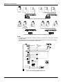
SERIAL COMMUNICATION NETWORK .................................................................................................................. 7.4
ETHERNET COMMUNICATION NETWORK............................................................................................................ 7.4
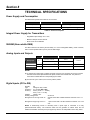
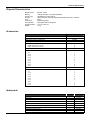
SECTION 8 - TECHNICAL SPECIFICATIONS............................................................................................8.1
POWER SUPPLY AND CONSUMPTION ................................................................................................................. 8.1
INTEGRAL POWER SUPPLY FOR TRANSMITTERS ............................................................................................. 8.1
NVRAM (NON-VOLATILE RAM) ............................................................................................................................... 8.1
VIII
Table of Contents
ANALOG INPUTS AND OUTPUTS........................................................................................................................... 8.1
DIGITAL INPUTS (DI1 TO DI8) ................................................................................................................................. 8.1
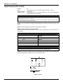
DIGITAL OUTPUTS (DO1 TO DO8) ......................................................................................................................... 8.2
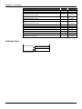
INSTALLATION CONDITIONS.................................................................................................................................. 8.4
FRONT PANEL.......................................................................................................................................................... 8.4
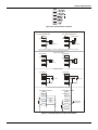
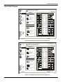
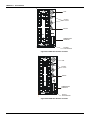
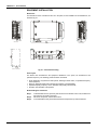
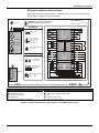
REAR PANEL DIAGRAM .......................................................................................................................................... 8.5
PHYSICAL CHARACTERISTICS .............................................................................................................................. 8.7
ACCESSORIES......................................................................................................................................................... 8.7
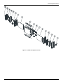
SPARE PARTS.......................................................................................................................................................... 8.7
ORDERING CODE .................................................................................................................................................... 8.8
SECTION 9 - INSTALLATION .....................................................................................................................9.1
INITIAL INSPECTION................................................................................................................................................ 9.1
LOCAL CONDITIONS FOR INSTALLATION .........................................................................................................................9.1
ENVIRONMENT CONDITIONS..............................................................................................................................................9.1
PRECAUTIONS AGAINST ELECTROMAGNETIC NOISE ....................................................................................................9.1
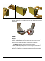
EQUIPMENT INSTALLATION................................................................................................................................................9.2
WIRING ..................................................................................................................................................................................9.3
CD600 VERSUS CD600 PLUS ................................................................................................................................. 9.7
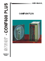
CONF600 PLUS
INTRODUCTION ..................................................................................................................................................... 10.1
MAIN FEATURES.................................................................................................................................................... 10.1
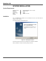
SECTION 10 - SYSTEM INSTALLATION .................................................................................................10.3
SYSTEM REQUIREMENTS .................................................................................................................................... 10.3
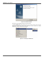
INSTALLATION ....................................................................................................................................................... 10.3
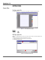
SECTION 11 - OPERATION ......................................................................................................................11.1
PROJECT FILES ..................................................................................................................................................... 11.1
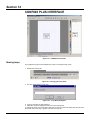
CREATING A PROJECT FILE .............................................................................................................................................11.1
OPENING A PROJECT FILE ...............................................................................................................................................11.1
SAVING A PROJECT FILE ..................................................................................................................................................11.2
DOCUMENT INFORMATION...............................................................................................................................................11.2
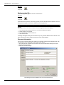
IMPORTING A PROJECT FILE............................................................................................................................... 11.3
EXPORTING THE CONFIGURATION .................................................................................................................... 11.3
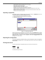
PRINTING DOCUMENTS ....................................................................................................................................... 11.3
PRINT CONFIGURATION....................................................................................................................................... 11.4
PRINT PREVIEW .................................................................................................................................................... 11.5
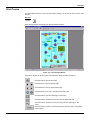
SECTION 12 - CONF600 PLUS INTERFACE ...........................................................................................12.1
NAMING LOOPS ..................................................................................................................................................... 12.1
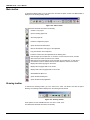
MAIN TOOLBAR...................................................................................................................................................... 12.2
DRAWING TOOLBAR ............................................................................................................................................. 12.2
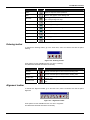
ORDERING TOOLBAR ........................................................................................................................................... 12.3
ALIGNMENT TOOLBAR.......................................................................................................................................... 12.3
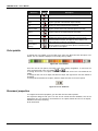
COLOR PALETTE ................................................................................................................................................... 12.4
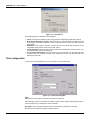
DOCUMENT PROPERTIES.................................................................................................................................... 12.4
OBJECT PROPERTIES .......................................................................................................................................... 12.7
DOCUMENT PROPERTIES TOOLBAR.................................................................................................................. 12.7
COMMUNICATIONS TOOLBAR ............................................................................................................................. 12.7
SELECTING THE LANGUAGE ............................................................................................................................... 12.7
CONVERTING THE CONFIGURATION LIST TO GRAPHICS ............................................................................... 12.7
LOOK EDITION ....................................................................................................................................................... 12.8
SECTION 13 - RESIDENT CONFIGURATION ..........................................................................................13.1
SECTION 14 - PROJECT CONFIGURATION ...........................................................................................14.1
ACTIVATING THE BLOCK LIST ............................................................................................................................. 14.1
IX
CD600 Plus - User’s Manual
ADDING BLOCKS TO THE BLOCK LIST ............................................................................................................... 14.1
ADDING BLOCKS TO THE DRAWING AREA........................................................................................................ 14.2
DRAGGING BLOCKS ON THE DRAWING AREA.................................................................................................. 14.3
ADDING THE COMMUNICATION BLOCK ............................................................................................................. 14.3
CHANGING BLOCK PARAMETERS ...................................................................................................................... 14.4
DELETING BLOCKS ............................................................................................................................................... 14.4
CHANGING THE BLOCK FORMAT........................................................................................................................ 14.5
SECTION 15 - LINKING BLOCKS.............................................................................................................15.1
CREATING A DIRECT LINK ................................................................................................................................... 15.1
CREATING A LINK WITH INTERRUPTION............................................................................................................ 15.2
CREATING A COMMUNICATION LINK.................................................................................................................. 15.3
EDITING THE LINK PROPERTIES......................................................................................................................... 15.4
REDRAWING A LINK .............................................................................................................................................. 15.4
REMOVING A LINK................................................................................................................................................. 15.4
SECTION 16 - COMMUNICATION ............................................................................................................16.1
CHECKING THE CONTROLLER ............................................................................................................................ 16.1
CONFIGURING THE COMMUNICATION............................................................................................................... 16.1
INITIALIZING THE COMMUNICATION................................................................................................................... 16.2
UPLOADING THE DEVICE CONFIGURATION...................................................................................................... 16.3
DOWNLOADING THE CONFIGURATION TO THE DEVICE ................................................................................. 16.4
SHOWING COMMUNICATION VALUES................................................................................................................ 16.4
MONITORING THE PARAMETERS OF A BLOCK................................................................................................. 16.5
UPDATING THE CONFIGURATION....................................................................................................................... 16.5
SECTION 17 - CALIBRATION...................................................................................................................17.1
ANALOG INPUT ...................................................................................................................................................... 17.1
ANALOG INPUT CALIBRATION - AUTOMATIC MODE......................................................................................... 17.2
ANALOG INPUT CALIBRATION - MANUAL MODE ............................................................................................... 17.3
CURRENT OUTPUT ............................................................................................................................................... 17.4
VOLTAGE OUTPUT ................................................................................................................................................ 17.4
SECTION 18 - CONF600 PLUS TUTORIAL..............................................................................................18.1
STARTING THE CONFIGURATOR ........................................................................................................................ 18.2
CREATING A NEW CONFIGURATION .................................................................................................................. 18.2
BUILDING THE STRATEGY ................................................................................................................................... 18.2
ADDING BLOCKS ................................................................................................................................................................18.2
MOVING BLOCKS ...............................................................................................................................................................18.4
LINKING FUNCTION BLOCKS ............................................................................................................................... 18.4
CREATING ALL LINKS ........................................................................................................................................... 18.5
REDRAWING LINKS ............................................................................................................................................... 18.5
CHECKING THE ENVIRONMENT .......................................................................................................................... 18.6
CHANGING PARAMETER VALUES....................................................................................................................................18.6
CHANGING PARAMETER VALUES OF THE PID (043) BLOCK ........................................................................................18.6
CHANGING PARAMETER VALUES OF THE AI (001) BLOCK ...........................................................................................18.6
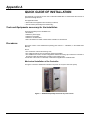
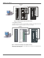
APPENDIX A - QUICK GUIDE OF INSTALLATION .................................................................................. A.1
TOOLS AND EQUIPMENTS NECESSARY FOR THE INSTALLATION ..................................................................A.1
PROCEDURES .........................................................................................................................................................A.1
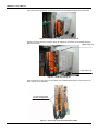
MECHANICAL INSTALLATION OF THE CONTROLLER ..................................................................................................... A.1
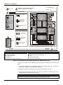
ELECTRICAL INSTALLATION OF THE CONTROLLER ...................................................................................................... A.3
CONTROL STRATEGY CONFIGURATION.......................................................................................................................... A.5
ESTABLISHING THE COMMUNICATION BETWEEN THE CONTROLLER AND THE COMPUTER.................................. A.5
APPENDIX B............................................................................................................................................... B.1
RETURNING MATERIALS ........................................................................................................................................B.1
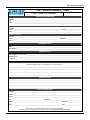
FSR – SERVICE REQUEST FORM..........................................................................................................................B.3
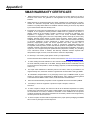
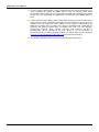
APPENDIX C - SMAR WARRANTY CERTIFICATE .................................................................................. C.1
X
Section 1
OPERATION
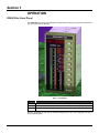
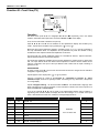
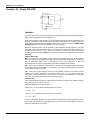
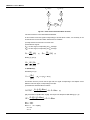
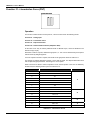
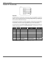
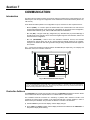
CD600 Plus Front Panel
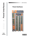
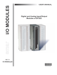
The CD600 Plus front panel has 3 bargraphs, an alphanumeric display, a group of keys for adjustment
and control and LEDs for signaling.
Fig 1.1 - Front Panel
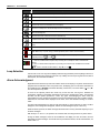
Bargraph
Description
SP
Indication of monitored loop's Setpoint it is indicated on the green 101 LEDs bargraph.
PV
Indication of the monitored loop's Process Variable. It is indicated on the red 101 LED's bargraph.
MV
Indication of the monitored loop's Manipulated Variable. It is indicated on the red 41 LEDs bargraph.
Since the visualization of each loop can be freely configured by the user. The 3 bargraphs may also be
used for other purposes.
1.1
CD600 Plus - User’s Manual
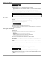
Keys
Description
Selects the variable to be shown in the alphanumeric display.
Selects the loop to be monitored on the front panel.
Increases the value of the variable shown on the display.
Decreases the value of the variable shown on the display.
Selects the Local Setpoint or the Remote Setpoint of the monitored loop.
Alarm Acknowledgement
Selects the Automatic or Manual mode of the monitored loop.
Increases the MV value, when the control is in Manual. When touched shows the output value on the display.
Decreases the MV value, when the control is in Manual. When touched shows the output value on the
display.
Fail: When lit, indicates that the controller is in fault condition.
Cycle: Blinks every 10 cycles, during cycle time adjustment (refer to section 8 communication).
Adjust: When lit, indicates that the variable, which is being shown on the display, can have its value
changed by the keys <
> and <
>.
1, 2, 3 or 4 – When lit, indicates that the variables, shown on the front panel refer, to the respective loop.
L – - When lit, indicates that the respective loop is working with Local Setpoint. Unlit L means Remote
Setpoint.
M – When lit, indicates that the respective loop is working in the Manual mode. Unlit M means Automatic
Operation.
or
- When lit, indicates an alarm situation – High ( ) or Low ( ).
Loop Selection
A short touch on the <LP> key lets the display shows the Tag (see below) of the loop being monitored. A
longer touch transfers the monitoring to the next Loop. Initially, the new Loop's Tag is shown and, after a
few seconds, the monitored information.
Alarm Acknowledgment
Regardless of the selected Loop and of the variable shown on the display, if any alarm, which has been
programmed to be indicated on the front panel occurs, the display goes on to show the information of
the variable and the "*ALARM" information alternately. Furthermore, one of the LED's < > or < >
from the respective loop, blinks.
As soon as the operator presses the <ACK> key for the first time, the Tag that identifies the
configuration, appears on the display, followed by the mnemonic message of the alarm. The message
will blink until the operator presses the <ACK> key again, acknowledging the alarm. After the
acknowledgement, the message stops blinking and remains displayed if the alarm condition persists.
Otherwise, the next alarm will be displayed on the stack, or the "NO ALARM" message, if no alarm
exists.
The alarm acknowledgement can also be made automatically. It means that when an alarm condition
disappears, the message also disappears, without the acknowledgment by the <ACK> key.
While the alarm is present, the alarm message remains stored in memory stack with capacity for up to
36 alarm messages.
With the keys <Δ> and <∇>, the operator can scroll the stack, checking if there is any other alarms.
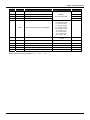
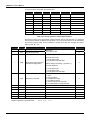
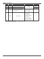
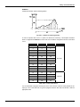
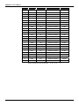
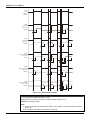
Among the alarm messages, which can be visualized on the display, the user can write 8, and the
remainders are fixed messages. The blocks that can provide these alarms, and its characteristics, are
listed in table 1.1.
1.2
Operation
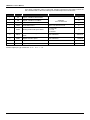
BLOCK
TYPE
CONFIGURABLE
MNEMONIC
DEFAULT MNEMONIC
001
BURNOUT
AI1 OUT
NO
002
BURNOUT
AI2 OUT
NO
003
BURNOUT
AI3 OUT
NO
004
BURNOUT
AI4 OUT
NO
005
BURNOUT
AI5 OUT
NO
006
BURNOUT
AI6 OUT
NO
007
BURNOUT
AI7 OUT
NO
008
BURNOUT
AI8 OUT
NO
009
DEV/BURNOUT
AO1 OUT
NO
010
DEV/BURNOUT
AO2 OUT
NO
011
DEV/BURNOUT
AO3 OUT
NO
012
DEV/BURNOUT
AO4 OUT
NO
039
DEVIATION
DEV - 1
NO
040
DEVIATION
DEV - 2
NO
041
DEVIATION
DEV - 3
NO
042
DEVIATION
DEV - 4
NO
077 (1º comp.)
LOW/EQUAL/HIGH
LOW COMP
YES
077 (2º omp.)
LOW/EQUAL/HIGH
HGH COMP
YES
078 (1º comp.)
LOW/EQUAL/HIGH
LOW COMP
YES
078 (2º comp.)
LOW/EQUAL/HIGH
HGH COMP
YES
079 (1º comp.)
LOW/EQUAL/HIGH
LOW COMP
YES
079 (2º comp.)
LOW/EQUAL/HIGH
HGH COMP
YES
080 (1º comp.)
LOW/EQUAL/HIGH
LOW COMP
YES
080 (1º comp.)
LOW/EQUAL/HIGH
HGH COMP
YES
081
UPPER LIMIT
LIM H 01
NO
081
LOWER LIMIT
LIM L 01
NO
081
VELOCIDADE
VELOC 01
NO
082
UPPER LIMIT
LIM H 02
NO
082
LOWER LIMIT
LIM L 02
NO
082
VELOCIDADE
VELOC 02
NO
083
UPPER LIMIT
LIM H 03
NO
083
LOWER LIMIT
LIM L 03
NO
084
VELOCIDADE
VELOC 03
NO
085
UPPER LIMIT
LIM H 04
NO
085
LOWER LIMIT
LIM L 04
NO
085
VELOCIDADE
VELOC 04
NO
Table 1.1 - Alarm Characteristics
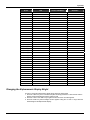
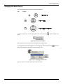
Changing the Alphanumeric Display Bright
In order to change the alphanumeric display bright, follow the steps below:
1. Press the <ACK> key in the controller front panel and keep pressed for a few seconds until the
display and frontal keyboard functions change to PID.
2. Press the <ACK> and <DSP> keys together until the ID of the controller appears.
3. Press the <DSP> key until the “Bright” function appears. Using the <Δ> and <∇> keys, select the
desired bright for the alphanumeric display.
1.3
CD600 Plus - User’s Manual
1.4
Section 2
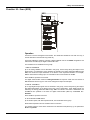
TUNING
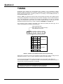
Proportional gain, Integral time and Derivative time constants of any Proportional, Integral,
Derivative (PID) block existing in the controller's configuration may be adjusted from the front panel
without using the Programmer. To make it possible, it is necessary to set the CACT parameter, of
the respective PID block, to "0" or "1".
Keep the <ACK> key pressed for a few seconds, until it changes the function of the display and the
front keyboard. Regardless of the previously shown variable, the display shows the PID proportional
gain, of the selected loop. In case there is more than one PID block on the loop (e.g. Cascade
control), the proportional constant refers to the lowest number PID block. In this case, the user
should know the blocks in the loop, in order to identify the “MASTER” and “SLAVE” PID.
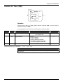
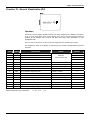
The mnemonic of each constant is composed of two letters that identify the action type, and a
number, that identifies the PID block that it belongs to.
KP : Proportional Gain
TR : Integral Time or Reset (min/rep.)
TD : Derivative Time (min)
1
BLK039
1º
2
BLK040
2º
3
BLK041
3º
4
BLK042
4º
5
BLK043
1º
6
BLK044
2º
7
BLK045
3º
8
BLK046
4º
PID Advanced
PID Simple
Table 2.1 – Number of the PID block related to the front panel tuning
When there is more than one loop in the controller, use the <LP> key in order to change the PID
parameters. Use the <Δ> and <∇> keys to change the values of the PID constants.
The scroll of all tuning parameters of all the PID blocks of a Loop is made by the <DSP> key.
The front panel keys (DSP, Δ, ∇, ACK) return to their normal functions by pressing the key <LP> or
in 20 seconds, if any key frontal panel is not actuated.
NOTE
a-) Tuning by the front panel can be disabled through the configuration.
b-) Tuning can be done by a PC connected to the communication port.
2.1
CD600 Plus - User’s Manual
2.2
Section 3
PROGRAMMING
Operation
The programming of the SMAR CD600 Digital Controller is based on the concept of freely
interconnectable Function Blocks. The interconnection is done in accordance to the control
strategy defined by the user.
All the function blocks already exist in a part of the memory not accessible by the user.
Programming the controller means to configure it by calling the necessary blocks into the user
memory, NVRAM, link them together, set their Characterization and Adjustment parameters to fit
a specific application.
Exchange of information between the used control algorithm and the process is done by means of
the input and output Function Blocks (both analog and digital). By these blocks the programmed
configuration is "physically" connected to the controller terminal block. Therefore, for example, the
Analog Input block No.1 can only be used for reading and processing the signal which is connected
to the terminal 001 (first analog input).
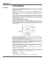
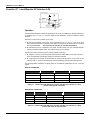
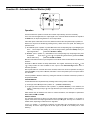
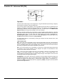
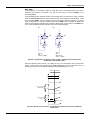
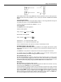
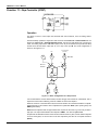
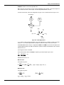
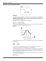
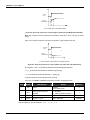
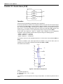
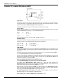
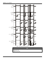
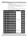
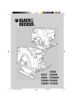
TYPICAL DESCRIPTION OF A BLOCK
The blocks described in Section 4 have a Control Function, consisting of one or more
mathematical and/ or logical operations. The function will relate block inputs with block outputs. The
inputs are designated by letters (A, B, C...), and outputs are designated by numbers. Exceptions are
the Analog and Digital input and output blocks, whose inputs, respectively outputs, are related to
hardwired terminals.
A
HIGH
139/141
143/145
LOW
140/142
144/146
HIGH
LOW
SELECTOR
B
C
ANALOG
INPUTS
D
DISCRETE INPUTS
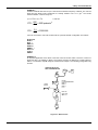
Fig 3A - Typical Block
The numbers related to the block outputs are addresses. Each number refers exclusively to a
certain output of a certain block and vice versa.
Each block has one Linking Parameter (L) for each input. A block with 3 inputs has the Linking
Parameters LIA, LIB, and LIC (Link Input A, B and C). If the HIGH-LOW selector block shown in
Figure 3A has LIA=2, that means that the input A of that block is on.
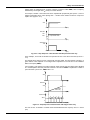
As a block can perform several operations, the activations of these operations are defined by the
Characterization Parameters. For example, the Analog Input block offers a choice of
implementing SQuare Root extraction (CSQR=1) or not (CSQR=0). It offers also a choice to use
LINearization (CLIN=1) or not (CLIN=0) - (See Figure 3B).
Constants in the Function Blocks that require frequent changes during process operation are called
Adjustment Parameters (ADJ Parameters). The same Analog Input block has an adjustable filter,
which has a time constant adjustable by ATIM.
There are two types of signals between blocks: scalar and discrete. Scalar are continuous signals
while discrete are on-off type of signals.
The signal transfer through block link is always made in the form of percentage, even if the signal is
discrete (0% for low logical level 0 and 100% for high logic level 1). A scalar signal, connected to an
input prepared to receive discrete signals, will be interpreted as follows:
- less than 70%:
- more than 80%:
- between 70% and 80%:
level 0
level 1
previous state
The output signal of a block can be received by as many inputs of blocks as desired.
3.1
CD600 Plus - User’s Manual
THE LOOPS
A Loop is a set of interconnected blocks with a certain purpose. It has a single man-machine
interface for the manipulation and visualization of data by the front panel of the controller. The
maximum number of loops per CD600 is 4.
The CD600's program also offers a configuration workspace named General Loop, "LOOP G"
which contains only blocks that may be simultaneously used by more than one loop. An example of
information maintained in the General Loop are the coordinates of the points used by a linearization
curve that may be used by several Analog Inputs simultaneously.
Tags
The Tag (Loop identification, see below) of the General Loop will always be the Tag of the whole
configuration. All configurations must have a General Loop, even if the program contains only one
control Loop. If no blocks are configured for the General Loop, at least a Tag must be given.
How to Program the CD600 Plus
When the CD600 Plus leaves the factory, with a default configuration named "4 LOOPS" (see
Section 5). This configuration can be changed to fit a particular application, or can be replaced by a
new one.
A program can be created, can be changed, or have its parameters modified through a PC. The PC
will need an appropriate interface, the CONF600 Plus. The CONF600 Plus is a powerful user
interface; it can be installed in a laptop or PDA and can be executed in the field as far as the
hardware allows. The configuration is drawn with control blocks and links, in part, as a control
diagram or a wiring diagram in a CAD system. In the Help windows, parameter information, options
and limits can be found.
The CONF600 Plus allows continuous access to all parameters and input/output monitoring
parameters of the blocks, becoming easier to troubleshoot configuration failures. The CONF600
Plus also supplies user documentation with configuration hardcopies, and disk storage. Please refer
to the CONF600 Plus section in this manual for further details.
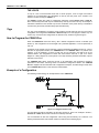
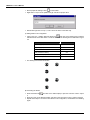
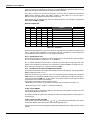
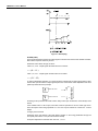
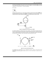
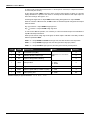
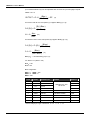
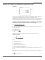
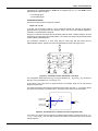
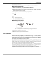
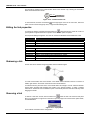
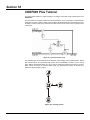
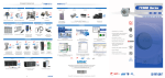
Example of a Configuration
The following control strategy can be implemented on the CD600 Plus:
Figure 3.1. Designed Control Loop
The Fluid B flow should be controlled to be the same as Fluid A. There is an example in section 4,
Function 12 - ARTH, where Fluids A and B are constantly controlled.
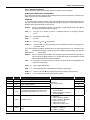
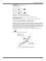
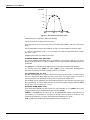
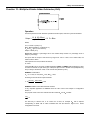
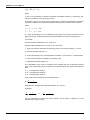
It is recommended to draw the configuration control using the block library as a reference. The
drawing should have block and terminal numbers, as indicate in the following figure:
3.2
Programming
Figure 3.2. Configuration of a Control Loop
The procedures above described are used to configure the controller through the CONF600 Plus.
There will be only one loop in the new configuration. It is necessary to adjust the identification
address of the CD600 Plus.
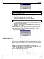
A) Adjusting the identification address of the CD600 Plus:
• Press the <ACK> key in the front panel of the CD600 Plus and keep it pressed for a few
seconds until the display changes its message.
• Then, press the <ACK> and <DSP> keys together, the panel will show the controller’s ID
address.
• Adjust the numeric values on the display using the keys <Δ> or <∇>. When the address is “1”, it
means the controller only accepts communication from the Hand-Held Terminal. Addresses
from “2” to “30” are the addresses programmed for the controller on the serial communication
network.
• Click on the <LP> key to return to normal operation.
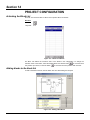
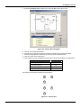
B) Starting up the CONF600 Plus:
• From the Start menu, open Programs > Smar > CONF600 Plus > CONF600 Plus.
3.3
CD600 Plus - User’s Manual
•
•
Start a project file clicking in New,
, on the toolbar.
Right click on Loop G on the palette and type “FIC100” as project name.
•
With another right click on Loop 1, “Flow” can be the name of the other loop.
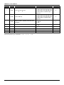
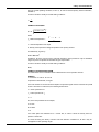
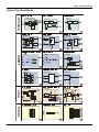
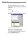
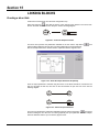
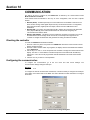
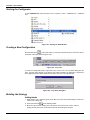
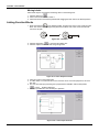
C) Adding blocks in the configuration:
•
Click on the Loop 1 palette. Select the Node tool,
, and click on the drawing area to add the
indicated blocks in the table below. Locate the blocks in the drawing area as indicated in figure
3.3.
Function Block
•
Block ID
AI (Analog Input)
001
AI (Analog Input)
002
Simple PID
043
A/M (Auto/Manual Station)
035
CO (Current Output)
009
FV (Front View)
027
The drawing area should look like this:
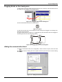
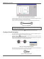
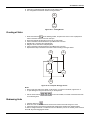
D) Connecting the blocks:
•
•
•
3.4
Select the Node tool,
, and click on the AI Block (001) to open the Link menu. Click in output
2.
Place the cursor on the PID block (043), and click on the Link menu to open it. Click in output B.
Repeat these steps to connect the other blocks in this configuration, as indicated in the following
figure:
Programming
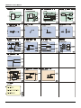
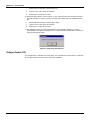
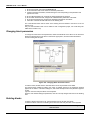
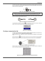
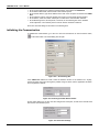
E) Editing the parameters:
•
Click on the Select tool,
, and right click on the block for the popup menu to appear. Select
the option Edit Parameters to open the dialog box of each block and adjust the parameter values
as indicated in the following table:
Function Block
Parameters
Description
Default Value
New Value
PID (043)
AKp
Proportional Gain
0.30
1.20
PID (043)
ATr
Reset Time (min/cycle)
10.00
2.00
AI (001)
CSQR
Square Root
0.00
1.00
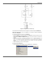
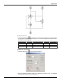
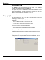
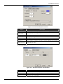
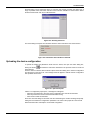
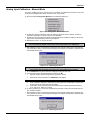
F) Initializing the communication:
•
Click the Online button,
•
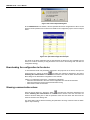
Select the identification address number in the Address box and click in Look. The CONF600
Plus will search for devices connected to the PC.
, to open the Online dialog box .
3.5
CD600 Plus - User’s Manual
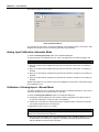
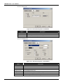
G) Downloading the configuration:
• Once the controller is selected, click on Download to download the block configuration for the
controller.
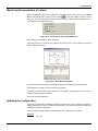
H) Monitoring the blocks: The block outputs can be monitored while the controller is operating, thus
not disturbing the process. The user can monitor the block output, by selecting the block and
pressing the <M> key.
• On the Online dialog box, click in the Go Online button for the values to be shown.
3.6
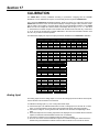
Section 4
FUNCTION BLOCKS LIBRARY
4.1
CD600 Plus - User's Manual
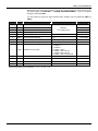
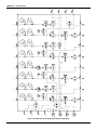
Function Table
FUNCTION
4.2
MNEM
BLOCK NUMBER
DESCRIPTION
PAGE Nº
01
AI
001/002/003/004/005/006/007/008
ANALOG INPUT
4.3
02
CO
009/010/011/012
CURRENT OUTPUT
4.4
03
VO
013/014/015/016
VOLTAGE OUTPUT
4.5
04
DI
017/018
DIGITAL INPUT
4.6
05
DO
019/020/021/022/023/024/025/026
DIGITAL OUTPUT
4.7
06
FV
027/028/029/030
FRONT VIEW
4.8
07
L/R
031/032/033/034
LOCAL/REMOTE SP SELECTOR
4.10
08
A/M
035/036/037/038
AUTOMATIC/MANUAL STATION
4.13
09
APID
039/040/041/042
ADVANCED PID
4.17
10
PID
043/044/045/046
SIMPLE PID
4.26
11
STEP
047/048/049/050
STEP CONTROLLER
4.30
12
ARTH
051/052/053/054/055/056
MULTIPLIER-DIVIDER-ADDER-SUBTRACTOR
4.33
13
SQR
057/058
SQUARE ROOT
4.37
14
LIN
059/060
LINEARIZATION
4.38
15
LL
061/062
DERIVATIVE/LEAD-LAG
4.40
16
PTC
063/064
PRESSURE AND TEMPERATURE COMPENSATION
4.43
17
POL
065/066
POLYNOMIAL
4.47
18
TOT
067/068/069/070
TOTALIZATION
4.49
19
P/DI
071/072
PULSE TOTALIZATION INPUT
4.51
20
BAT
073/074
BATCH COMPARATOR
4.55
21
SPG
075/076
SETPOINT GENERATOR
4.56
22
ALM
077/078/079/080
DOUBLE ALARM
4.58
23
LIMT
081/082/083/084
LIMITER WITH ALARM
4.60
24
LOG
085/086/087/088/089/090
LOGIC
4.63
25
TMR
26
H/L
27
SSEL
28
ADJ
29
091/092
TIMER
4.65
093/094/095/096
HIGH/LOW SELECTOR
4.67
097/098
INTERNAL/EXTERNAL SELECTOR
4.68
099/100/101/102
CONSTANT ADJUSTER
4.69
ISEL
103/104/105/106
INPUT SELECTOR
4.70
30
OSEL
107/108
OUTPUT SELECTOR
4.71
31
PNT
109/110/111/112/113/114/115/116
LINEARIZATION CURVE
4.72
32
GV
117
GENERAL VISUALIZATION
4.75
33
K
118
CONSTANTS
4.76
34
SCN
119
SCAN
4.77
35
PRM
120
SCAN/ACTUATION OF THE PARAMETERS PID
4.79
36
ATU
121
ACTUATION
4.80
37
DIT
122/123/124/125
DIGITAL INPUT WITH TIMER CONTROL
4.83
Library of Function Blocks
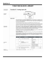
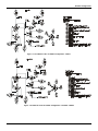
Function 01 - Analog Input (AI)
Operation
All the analog inputs have a corresponding Analog Input block. The analog input 2, for example,
which is connected to terminal 2, corresponds to block BLK002. The input to the circuit is always a
voltage signal (0-5 V or 1-5 V). If a current signal (0-20 mA or 4-20 mA) be used, a Shunt resistor
shall be placed in the corresponding terminal block position.
The input signal passes through an analog second order BESSEL filter with cutoff frequency at 15
Hz.
The result is converted into a digital number and in this form, it passes through a four point
calibration process in which 0V, 1V, 3V and 5V are made to correspond respectively to 0, 20, 60
and 100% for 0-20 mA/0-5 V input and -25, 0, 50 and 100% for 4-20 mA/1-5 V input. See the
CALIBRATION section for further details.
After conditioning, the signal is digitally filtered with an adjustable time constant. It can be linearized
in accordance with a curve established in the Function 31 - Linearization Curve (Blocks 109 to
116), configured in Loop G. This curve is selected by CLIN and may be used with 13 or 26 pairs of
points x, y, interconnected by straigh line segments. The curves that may be performed are show on
table 4.31.1 page 4.59.
The signal can also have square root extraction, selectable by CSQR. The square root has an
adjustable cutoff point (ACUT) for low signals. All values below ACUT will be considered 0%.
Parameter CSQR permits input signal selection (4-20 mA/1-5 V or 0-20 mA/0-5 V) and to decide
whether square root will be extracted.
In Burnout (signal after calibration smaller than -2% or greater than +102%), an Alarm can be
indicated on the front panel (if CFRT=1) and a Burnout alarm signal can be activated. This signal
can be used, for example, to switch the process variable to another input through a block of the
Function 29 - Input Selector or to force the controller's output to an emergency position.
TYPE
MNEM
DESCRIPTION
I
CFRT
"Burnout" indication on the front panel
I
CLIN
Linearization
(See Table 4.31.1 on Function 31 –
Linearization Curve)
I
CSQR
Signal Selection and Square Root extraction
P
ACUT
Cutoff level for square root extraction
0.00 - 100.00%
1.00%
P
ATIM
Filter time constant
0.00 - 30.00s
0.20s
Number of Bytes per Type of Parameter: A = 4
C=6
RANGE
0-No/1-Yes
2-Yes with Auto Ack
0-No
1?8/Curves 1?8
9-Curves 1 and 2
10-Curves 3 and 4
11-Curves 5 and 6
12-Curves 7 and 8
0-No (1 to 5V or 4 to 20mA)
1-Yes (1 to 5V or 4 to 20mA)
2-No (0 to 5V or 0 to 20mA)
3-Yes (0 to 5V or 0 to 20mA)
DEFAULT
0
0
0
L=0
4.3
CD600 Plus - User's Manual
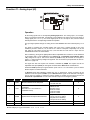
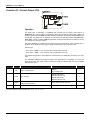
Function 02 - Current Output (CO)
Operation
The block input, in percentage, is calibrated and converted into an analog current signal. A
feedback of this current is sent to a comparator, which also receives the input signal. If there is a
deviation greater than the ADEV (allowable deviation) parameter, the discrete output Deviation will
be activated. This signal may, for example, be connected to the input H of a block of Function 06 Front View, in order to make the MV bargraph blink, warning the operator that something is wrong
or to activate any other type of alarm.
This alarm indicates, for example, that the current loop has an interruption. There is a parameter in
the block, which allows the output type to change according to the type of actuator used.
Actuator type:
- "Air to Open" - CVTP = 0 or 2 / output 0-100% corresponds to 4-20 mA
- "Air to Close" - CVTP = 1 or 3 / output 0-100% corresponds to 20-4 mA
This enables the operator to have always 0% corresponding to a closed valve and 100% to an open
valve.
It is essential to calibrate the output according to the specifications. For example, for a 0-20 mA
signal in block 011, the output current at terminal 35 shall be calibrated with 0-20 mA and CVTP
shall have the code 2.
TYPE
MNEM
I
LIA
DESCRIPTION
DEFAULT
Input A - Output Signal
Address
0 to 170/225 to 240
0
0-Direct (4 to 20 mA)
1-Reverse (20 to 4 mA)
2-Direct (0 to 20 mA)
3-Reverse (20 to 0 mA)
0
I
CVTP
Type of Output
I
CFRT
Front Panel Indication of deviation between the
0-No/1-Yes/2-Yes with Auto Ack.
desired and actual current
P
ADEV
Maximum allowable deviation
Number of Bytes per Type of Parameter: A = 2
4.4
RANGE
C=4
0.00 - 100.00%
L=2
0
5.00%
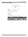
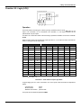
Library of Function Blocks
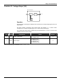
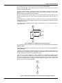
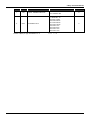
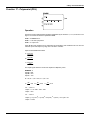
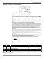
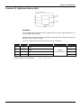
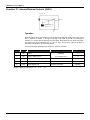
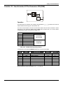
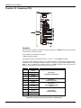
Function 03 - Voltage Output (VO)
BLK 013/014/015/016
CALIBRATION
A
VOLTAGE
DRIVER
6 /7/8/9
0%
100 %
Operation
The block input in percentage is calibrated and converted into an analog voltage signal sent to the
terminal block.
This block includes a parameter, which allows signal type selection, i.e., it makes 0-100%
correspond to 1-5 Vdc/0-5 Vdc (direct type) or to 5-1 Vdc/ 5-0 vdc (reverse type).
The corresponding output shall be calibrated as per the specifications to 1-5 Vdc or to 0-5 Vdc (see
Calibration Section for further details).
TYPE
MNEM
I
LIA
I
CVTP
DESCRIPTION
RANGE
DEFAULT
Input A - output signal
Address
0 to 170/225 to 240
0
Type of output
0 - Direct (1 to 5V)
1 - Reverse (5 to 1V)
2 - Direct (0 to 5V)
3 - Reverse (5 to 0V)
0
Number of Bytes per Type of Parameter: A = 0
C=2
L=2
4.5
CD600 Plus - User's Manual
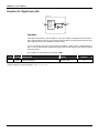
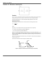
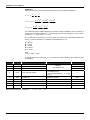
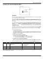
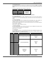
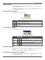
Function 04 - Digital Input (DI)
BLK 017/018
3-24V
OR OPEN
CONTACT
(HIGH LEVEL)
0-1,7V
OR CLOSED
CONTACT
(LOW LEVEL)
13
14
0
CH1
1
21/22
Operation
If the input block terminal is open (impedance > 50 KΩ) in relation to the Digital Ground terminal or
with a voltage between 3 and 24 Vdc, the signal will be considered as high logic level and the value
100% (high logic level) will be available in the block output.
If, on the other hand, the input is short-circuited (impedance < 200Ω) or with a voltage between 0
and 1.7 Vdc, the signal will be considered as low logic level and the value 0% (low logic level) will be
at the block output.
This condition can be inverted by the parameter CNOT.
TYPE
MNEM
DESCRIPTION
RANGE
I
CNOT
Inverts Interpretation
0 - No/1 – Yes
Number of Bytes per Type of Parameter: A = 0
4.6
C=2
L=0
DEFAULT
0
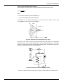
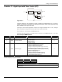
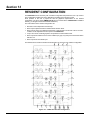
Library of Function Blocks
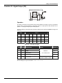
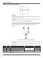
Function 05 - Digital Output (DO)
Operation
This block can perform a logic operation with inputs A and B. The output is sent to a two-position
selector switch. The other position is connected to input C. A high logic level at D, switches CH1 to
position "1", making the output equal to safety input C.
The logic operation to be performed by the block is defined by the parameter CLOG according to the
table 4.5.1:
INPUT
OUTPUT
A
B
OR
AND
XOR
NOR
NAND
NXOR
0
0
0
0
0
1
1
1
0
1
1
0
1
0
1
0
1
0
1
0
1
0
1
0
1
1
1
1
0
0
0
1
Table 4.5.1 - Truth table for digital
TYPE
MNEM
DESCRIPTION
RANGE
I
LIA
Input A
I
LIB
Input B
I
LIC
Safety input C
I
LID
Input D to activate safety input
I
CLOG
0
Addresses
0
0 to 170/225 to 240
0
0
0 - OR/1 - AND/2 - XOR
3 - NOR/4 - NAND/5 - NXOR
Logic function
Number of Bytes per Type of Parameter: A = 0
DEFAULT
C=2
0
L=8
4.7
CD600 Plus - User's Manual
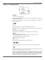
Function 06 - Front View (FV)
Operation
This block leads inputs A, B, C to bargraphs SP, PV and MV respectively, and in the default
condition, associates these inputs to the mnemonics SP, PV and MV on the display.
Thus, the use of this block is limited to one per loop.
Inputs A, B, D, E, F and G can be visualized on the alphanumeric display and scrolled by key
<DSP>. Input C will be visualized only by pressing key < > or key < >.
Blocks that have manual adjustment registers, operated by keys <Δ> or <∇> must be connected to
the Loop Visualization block. An adjustment can be performed only while the variable is being
visualized; the LED "Adjust" indicates that adjustment can be done.
The blocks with the manual adjustment feature are Local/Remote Selector, Setpoint Generator,
Internal/ External Selector and Constant Adjuster.
The blocks with adjustment capability have the outputs identified by numbers equal or greater than
225. The Input Selector block also allows manual adjustment of blocks with this feature whose
output is connected to the Input of the Input Selector block. Notice that its output numbering is
greater than 225.
VISUALIZATION
All inputs, except C and G, may have the three-character mnemonics changed and the indication
configured in engineering units.
Input C appears on the display when < > or < > is pressed.
Input G, if connected to a block of the Function 18 - Totalization or Function 19 - Pulse
Totalization Input, will show an eight-digit number. Connecting it to any other block, it will operate
as a 4 digit display.
Input H - Bargraph Flashing - can be used to blink the MV bar. It is activated with a high logic level
signal. This input can be used, for example, to show a deviation or break in the current output from a
block of Function 02 - Current Output.
If one of the inputs A, B, D, E or F be shown in the Alphanumeric Display and its indication in
engineering units exceeds 10000, the display will show the message "++++" instead of the input
value. If this indication be lower than -10000, the message displayed will be " - - - -".
TYPE
MNEM
I
LIA
Input A - SP
0
I
LIB
Input B - PV
0
I
LIC
Input C – MV
0
I
LID
Input D
Addresses
0
I
LIE
Input E
0 to 170 / 225 to 240
0
I
LIF
Input F
0
I
LIG
Input G - Counter type Input
0
I
LIH
Input H - blink MV bargraph
0
4.8
DESCRIPTION
RANGE
DEFAULT
Library of Function Blocks
TYPE
MNEM
DESCRIPTION
M
AMSP
Three-character mnemonic for SP
***
R
ASPZ
0% for SP in engineering units
-10000 to 10000
0
R
ASPM
100% for SP in engineering units
-10000 to 10000
100.00
M
AMPV
Three-character mnemonic for PV
***
R
APVZ
0% for PV in engineering units
-10000 to 10000
0
R
APVM
100% for PV in engineering units
-10000 to 10000
100.00
M
AMND
Three-character mnemonic for D
***
R
A-DZ
0% for D in engineering units
-10000 to 10000
0
R
A-DM
100% for D in engineering units
-10000 to 10000
100.00
M
AMNE
Three-character mnemonic for E
***
R
A-EZ
0% for E in engineering units
-10000 to 10000
0
R
A-EM
100% for E in engineering units
-10000 to 10000
100.00
M
AMNF
Three-character mnemonic for F
***
R
A-FZ
0% for F in engineering units
-10000 to 10000
0
R
A-FM
100% for F in engineering units
-10000 to 10000
100.00
Number of Bytes per Type of Parameter: A = 60
RANGE
C=0
DEFAULT
SP
PV
MND
MNE
MNF
L = 16
4.9
CD600 Plus - User's Manual
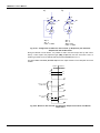
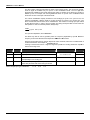
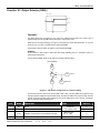
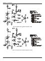
Function 07 - Local/Remote SP Selector (L/R)
BLK 031/032/033/034
L/R
A
RATE OF
CHANGE
LIMITER
0-R
0-R
CH1
CH2
225/226
227/228
REMOTE
31/33
35/37
LOCAL
32/34
36/38
1-L
1-L
B
DSP
REGISTER
C
Operation
This block allows Setpoint selection by pressing the key <L/R> (Local/Remote), Setpoint adjustment
by pressing keys <Δ> and <∇> and the selection and adjustment of several Setpoints related
functions.
Actuation in Local mode is possible in two ways:
a) By the internal Register of the block, which is actuated by the <Δ> and <∇> keys of the front
panel, when the Set Point is selected on the display. The output of the block must be connected
to a block of Function
06 - Front View or Function 32 - General Visualization.
b) By input B, that can be connected to the output of another block. The use of B automatically
cancels the internal register action. The block becomes an input selector.
Transfer from Local to Remote and vice versa is possible in two ways:
a) By using the <L/R> key of the front panel, that actuates the switch CH1. In this case, the LED "L"
of the corresponding loop will light up when Local mode is selected.
b) By a high logic level at input C, that actuates the switch CH2 and "forces" Local mode. In this
case, the LED "L" of the corresponding loop will remain blinking while input C is with high level.
The following tables summarize the block status for the different combinations of CH1, CH2 and
input B.
INPUT B CONNECTED
CH1
INPUT C
LED L
OUTPUT
R
0
-
INPUT A
R
1
FLASHING
INPUT B
L
0
LIT
INPUT B
L
1
LIT
INPUT B
Table 4.7.1 - Block output and LED action according CH1 (R/L key) and CH2 ("C" input)
position, with input "B" connected.
INPUT B NOT CONNECTED
CH1
INPUT C
LED L
OUTPUT
R
0
-
INPUT A
R
1
FLASHING
INTERNAL REGISTER
L
0
LIT
INTERNAL REGISTER
L
1
LIT
INTERNAL REGISTER
Table 4.7.2 - Block output and LED action according CH1 (R/L key) and CH2 ("C" input)
position, with input "B" not connected.
4.10
Library of Function Blocks
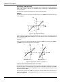
The controller can also be locked in Local or in Remote by the parameter CLKR.
After a power interruption, the controller will return to operation in the mode (Local or Remote)
selected by the parameter CTON.
The block features bumpless Local-Remote transfer, with adjustable changing rate (Slew Rate,
ASLW). This feature avoids abrupt changes in the Setpoint, and, consequently, in the process,
when the Setpoint is switched from Local to Remote.
Remote to Local transfer is balanced, that is, the Local register tracks the Remote Setpoint, when
operating in Remote mode. This can be used to implement Setpoint tracking when the loop is in
manual.
In a Setpoint tracking configuration the SP=PV in manual mode. The PV is manually adjusted to the
desired Setpoint by using the MV < > and < >. Then he can switch back to automatic mode and
the Setpoint will remain.
The LOG block inverts the MANUAL status signal to a AUTOMATIC, since Local Setpoint is desired
in automatic mode.
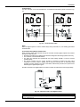
AI
001
2
B
D APID A
039 E
47
A
A/M 40
035
39
A
225 L/R
CLKR=1
031
131
A LOG CNOT=1
085 CLOG=0
A
CO
Fig 4.7.1 L/R Selector Configuration for Setpoint Tracking
The maximum and minimum limits for the Local Setpoint actuator are established in the parameters
ALOW and AUPP.
If it is necessary to have limits on the Remote Setpoint, this shall be done by means of Function 23 Limiter with Alarm.
In addition to the analog signal generated internally (in Local mode) or externally (in Remote Mode), the
block has two discrete outputs; the first is at high logic level when the block is in Remote mode and the
second is at high logic level when the operating mode is Local.
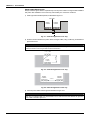
When one of the outputs 225/226/227 or 228 is visualized on the Alphanumeric Display and the
block is in Local mode, the register may be actuated by the Front Panel (Local Setpoint). Besides,
should this output signal be from inputs A or B (Remote Setpoint), and this input is linked to the
output of an adjustment block, this adjustment block will also be actuated by the Front Panel. This
feature is used in the following configuration.
ADD
099
233
A
L/R
031
255
A
FV
027
Fig 4.7.2 - L/R Selector Configuration for Internal or External Register Actuation
4.11
CD600 Plus - User's Manual
In the above configuration, when in Local mode, actuation is performed in the register of Block 031
and, in Remote mode, in Block 099, although the visualized output is that of Block 031.
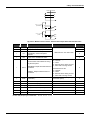
TYPE
MNEM
DESCRIPTION
I
LIA
Input A - Variable to Remote Mode
I
LIB
Input B - Variable to Local Mode
I
LIC
Input C - Forces Local Mode
I
CLKR
Locks switch CH1 in:
0-No Lock/1-Remote/2-Local
2
I
CTON
Starting condition after power failure
0 - Last mode
1 – Local
2 – Remote
0
P
ASLW
Maximum rate-of-change in Remote
mode
1.00 - 200.00%/s
200.00%/s
P
ASPD
Register actuation speed
0.00 - 200.00%/s
10.00%/s
P
ALOW
Register lower limit
-102.00 to +102.00%
0.00%
P
AUPP
Register upper limit
-102.00 to +102.00%
100.00%
Number of Bytes per Type of Parameter: A = 8
4.12
RANGE
C=4
L=6
DEFAULT
0
Addresses
0 to 170 / 225 to 240
0
0
Library of Function Blocks
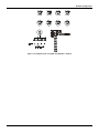
Function 08 - Automatic/Manual Station (A/M)
Operation
This block allows the operator to actuate the controller output directly, whenever necessary.
In the most common application, the output signal of one of the PID blocks is linked to the input A of
the A/M block, its output being linked to a current output block.
If the other inputs of this block are not used, switches CH3 and CH2 are permanently in position "0".
Switch CH1 may then be actuated by pressing the key <A/M> on the front panel, thus altering the
operation mode:
a) AUTOMATIC (CH1 in position "0"): letter M is unlit in the corresponding loop. Input A signal goes
to the
block output after passing by a rate-of-change limiter (parameter ASLW) and by an
output signal limiter
(parameters ALOW and AUPP).
b) MANUAL (CH1 in position "1"): letter M is lit in the corresponding loop. Output signal may then
be adjusted
by the keys < > and < >, its speed being determined by parameter ASPD,
with the limits set by
parameters ALOW and AUPP.
Manual to Automatic transfer may be bumpless or hard. Both modes are described in the PID block
functions.
Automatic to Manual transfer is always balanceless. The register, actuated by the keys < > and
< >, always tracks the value available at the output of the Rate-of-Change limiter while in
automatic operation.
After a power failure or a manual reset of the controller, switch CH1 returns to operation according to
parameter CHST; it may return in Manual, Automatic or in the last position prior to the power failure
or to the reset.
It is also possible to block the <A/M> key, locking the controller in Automatic or Manual, by means of
the parameter CCH1.
FORCED MANUAL
Forced Manual mode is implemented by actuating switch CH2 by means of input D:
a) A low logic level in D keeps CH2 in position "0"
(NORMAL OPERATION).
b) A high logic level in D switches CH2 to position "1" (FORCED MANUAL). In this situation, the
register actuated by the keys < > and < > takes the input value at position "0", just before the
switching.
Other features may be added to this mode. For further information, see description of parameters
CCH1, CST1, CLAM and CLMV.
SAFETY OUTPUT
The controller output may be driven to a safe value by switching CH3 to position "1", by means of
input C of the block. The output signal will then be the input B signal. This may be a constant or a
variable value, depending on which block it is originated.
If CH1 is in position "1" (equivalent to Manual), the letter M of the corresponding loop will be
continuously lit and the output signal will be the signal of input B in the instant prior to CH3
switching.
4.13
CD600 Plus - User's Manual
If CH1 is in position "0" (equivalent to Automatic), the letter M will blink faster than when in Forced
Manual and the signal at the output will be the same signal of input B.
The position of switch CH1 after input C returning to a low logic level is determined by parameter
CSA1, with the following options: last position, position "1" and position "0". This may imply in
Manual or Automatic operation if input D is with low logic level.
Other features may be added to this mode. For further information, see description of parameters
CCH1, CST1, CLAM and CLMV.
INPUT B CONNECTED
INPUTS
C
D
0
0
0
0
1
0
1
0
0
1
0
1
1
1
1
1
CH3
0
0
1
1
0
0
1
1
SWITCHES
CH1
CH2
0
0
1
0
0
0
1
0
0
1
1
1
0
1
1
1
OUTPUT
INPUT A
INTERNAL REGISTER
INPUT B
INTERNAL REGISTER
INTERNAL REGISTER
INTERNAL REGISTER
INTERNAL REGISTER
INTERNAL REGISTER
LED M
UNLIT
LIT
FAST FLASH
LIT
SLOW FLASH
LIT
SLOW FLASH
LIT
Table 4.8.1 - Truth table
Observe that the parameters CCHI, CST1 and CSA1 can affect the CH1 position in function of the
input C and/or D status independent of the A/M key. Although, configuration of those parameters
can automatically alter the table line, as it can suppress some lines.
CCH1 - ACTUATION OF CH1
This parameter determines if switch CH1 will be actuated only by the front panel or with CH2 and/or
CH3, or if it will be locked in "0" (AUTO) or in "1" (MANUAL).
CH1 is actuated simultaneously with CH2 or CH3 when inputs C or D, have high logic level. CH1
position, when actuated by CH2 and/or CH3 is described in parameter CST1. The position of CH1,
when CH3 returns to position "0", is defined in parameter CSA1.
CST1 - POSITION OF CH1 WITH CH2 AND CH3 ACTUATED
This parameter determines CH1 position when inputs C or D are with high logic level and parameter
CCH1 is programmed with 3, 4 or 5.
When input C returns to logic level "0", switch CH1 will take the position determined by parameter
CSA1. After CH1 is actuated by input D, it may be free to be actuated by the <A/M> key since this is
not locked (parameter CLAM=1 or 3). CH1 position when input D returns to a low logic level will be
the position of CH1 just before CH2 switching.
Such position is indicated on the front panel as follows:
- "M" blinking: CH1 in position "0" (equivalent to automatic when CH2 returns to position "0").
- "M" continuously lit: CH1 in position "1" (equivalent to Manual).
CLAM - LOCKS A/M KEY
This parameter locks the front panel <A/M> key, thus preventing the actuation of switch CH1 when
inputs C and/or D have high logic level.
This feature prevents the operator from actuating the <A/M> key during situations of "safety output" or
"forced manual".
CLMV - LOCKS < > AND < > KEYS
This parameter locks the front panel keys < > and < >, thus preventing the alteration of the output
value while in Manual mode, when inputs C and/or D have high logic level.
This prevents the operator from changing the output signal during situations of "safety output" or "forced
manual".
4.14
Library of Function Blocks
CHST - RESTART CONDITION
CHST configure the operating mode of the respective loop after a power interruption.
CLIM-OUTPUT LIMITER ONLY ON AUTOMATIC
The output limiter actuates normally in both operating modes: manual and automatic. CLIM allows the
limiter to actuate only on the automatic mode.
EXAMPLES:
1) As an emergency situation defined by a high logic level signal, the control output shall remain in the
last value prior to the emergency, unless the operator decides to change it. If the emergency situation
disappear, the control shall remain in manual mode.
Solution:
This is a "Forced Manual" situation. The emergency signal shall be linked to input D and
the following parameters shall be configured:
CST1 = 0 →
CH1 goes to or remains in position "1" (Manual) whenever an emergency situation
occurs.
CCH1 = 3 → Input D signal switches CH1.
CSA1 = →
any value.
CLMV = 0 → The keys < > and < > shall operate.
CLAM = 1→ Locks the <A/M> key, thus preventing CH1 to be switched to position "0", allowing return
in Automatic mode.
In the same emergency situation described above, the output signal shall go to 2%, remaining in this
value
throughout the emergency situation. When the emergency signal disappear, the controller
shall remain in
manual mode.
Solution:
This is a "Safety Output" situation. The emergency signal shall be linked to Input C, the
value 2% (from an adjustment block or a constant value block) shall be linked to Input B
and the following parameters shall be configured:
CST1 = 1 →
CH1 goes to or remains in position "0" (Auto). The output will be the input B value in the
instant of CH3 switching.
CCH1 = 4 → Input C signal switches CH1.
CSA1 = 1 → Controller shall remain in Manual after the emergency signal drops.
CLMV = 2 → The keys < > and < > are locked as long as the emergency signal is present.
CLAM = 2 → CH1 is locked since the emergency signal is present.
TYPE
MNEM
I
LIA
Input A (Automatic)
I
LIB
Input B (Safety)
I
LIC
Input C (Safety Switch)
I
LID
Input D (Forced Manual)
I
CST1
DESCRIPTION
CH1 position when inputs C or D have a high
logic level and parameter CCH1 ? 0, 1 or 2
RANGE
DEFAULT
0
Addresses
0 to 170 / 225 to 240
0
0
0
0 - Position 1 (Manual Position in
normal operation)
1 - Position 0 (Automatic Position in
normal operation)
I
CCH1
Actuation of CH1
0 - <A/M> Key
1 - Locks in Position 0 (AUTO)
2 - Locks in Position 1 (MANUAL)
3 - <A/M> Key or Input D
4 - <A/M> Key or Input C
5 - <A/M> Key or Inputs C or D
I
CSA1
CH1 position when input C returns to a low logic
level
0 - Last Position
1 - Position 1 - (MANUAL)
2 - Position 0 - (AUTO)
0
0
0
4.15
CD600 Plus - User's Manual
TYPE
I
MNEM
CLMV
DESCRIPTION
RANGE
Locks < > and < > keys
0 - No Lock
1 - When Input D has a high logic level
2 - When Input C has a high logic level
3 - When Inputs C or D have a high
logic level
0
0
I
CLAM
Locks <A/M> key
0 - No Lock
1 - When Input D has a high logic level
2 - When Input C has a high logic level
3 - When Inputs C or D have a high
logic level
I
CHST
Restart condition - Operating mode after power
interruption
0 – Last
1 – Manual
2 - Auto
0
I
CLIM
Output limiter only on Automatic
0 - Manual and Auto
1 - Auto
0
I
ASPD
Actuation Speed in Manual
0.00-200.00%/s
I
ALOW
Lower Limit
-2.00 to +102.00%
-2.00%
I
AUPP
Upper Limit
-2.00 to +102.00%
+102.00%
I
ASLW
Slew Rate for the Automatic mode
1.00 to 200.00%/s
200.00%/s
Number of Bytes per Type of Parameter: A = 8
4.16
DEFAULT
C = 14
L=8
10.00%/s
Library of Function Blocks
Function 09 - Advanced PID (PID)
BLK 039/040/041/042
A
B
SP
SP
PV
DEV
OUT
C
D
CURVE n
Y
EXT
47/49
51/53
PI.D
PID
I.PD
SAMPLING
PV
GAIN
X
DEVIATION
WITH TIME-OUT
ALARM
48/50
52/54
FEEDBACK
TRACK FB
E
Operation
This block offers a wide range of control algorithms, using the traditional Proportional (P), Integral (I)
and Derivative (D) modes in various arrangements.
There are two choices of PID algorithm: one is the parallel, ideal and the other is noninteractive, ISA
algorithm. Calculation of the PID prevents the saturation of the output by the integral mode (antireset-windup). Saturation limits are adjustable by the user, a unique feature of the SMAR CD600
Digital Controller, that brings more flexibility to the control strategy.
Manual to Automatic transfer may be bumpless or hard. Bumpless transfer makes the automatic
mode start from the last manual value prior to the switching. Hard transfer will add to this value the
proportional action: (Kp.e). In both cases the output signal of the block of Function 08 Automatic/Manual Station, must be connected to input D (Feedback) and the Status signal of the
Auto/Manual block must be connected to input E (track FB).
This block allows selection of the following control types: Sample and Hold, Quadratic Error, GAP
and Adaptative Gain.
TYPE OF PID (CTYP)
PI.D - The P and I act on the deviation, and D on the Process Variable. In this way, the output signal
follows the changes of the Setpoint according to the Proportional and Integral actions, but does not
give an undesirable impulse due to the Derivative action. This option is the most recommended for
the majority of applications with Setpoint adjustable by the operator.
PID - The P,I and D actions act on the deviation. In this way, the output signal changes when there
are changes on the Process Variable or on the Setpoint. This option is recommended for ratio
control or for the slave controller of a cascade.
I.PD - In this type only the Integral mode acts on the deviation. Changes on the Setpoint cause
variation of the output according to the Integral mode, which is a very smooth effect. It is
recommended for processes that can be upset by abrupt changes of the Setpoint. This is the case
of heating processes with high proportional gain.
PI-SAMPLING - In this option, when there is a deviation, the output signal changes according to the
PI algorithm during a time t0. Then, the output signal is kept constant during a time t1. If the deviation
persists, the signal will vary again during t0, and will remain constant during t1. The period is t0+t1,
(adjusted by CSAM), and the actuation time is t0 (adjusted by CSON). This type is recommended for
processes with high dead time.
4.17
CD600 Plus - User's Manual
Fig 4.9.1 - PI Sampling
ACTION (CACT)
There are processes that require the output signal to increase when the Process Variable increases,
while others require the other way around.
Parameter CACT selects the type of action:
TYPE 0, 2, 4 or 6 - Output signal decreases when PV increases
e = ( SP − PV )
TYPE 1, 3, 5 or 7 - Output signal ncreases when PV increases.
e = ( PV − SP)
In order to standardize operation, it is recommended to consider that an output signal equal to 100%
means valve open and that an output signal equal to 0% means valve closed. Operation of the front
panel keys follows the same principle:
100%
0
0%
C
OPENS THE VALVE
CLOSES THE VALVE
According to this procedure MV=100% means always valve open and MV=0% means always valve
closed.
If the actuated valve is "Air-to-open", MV=100% must be equivalent to 20 mA. Valves type Air-toclose will require 100% being equivalent to 4 mA. This may be selected in Function 02 - Current
Output.
Tuning by the Front Panel
Parameter CACT also defines if the block allows changes on the tuning parameters through the
front panel push buttons or not (see PID constants ahead).
Front panel adjustment is selected when CACT=0, 1, 4 or 5.
4.18
Library of Function Blocks
Control Algorithm
The CD600 offers two control algorithms:
Parallel or Ideal algorithm
MV(t ) = K p e(t ) +
1
TR
. ∫ e(t )dt + T D
de(t )
dt
Noninteractive or ISA algorithm
MV(t ) = K p [e(t ) +
1
TR
. ∫ e(t )dt + T D
de(t )
]
dt
Parameters 0, 1, 2 or 3 select the parallel or ideal.
Parameters 4, 5, 6 or 7 select the noninteractive or ISA.
For the noninteractive option, when Kp=0 the controller is automatically set as ID.
QUADRATIC ERROR (CETY)
The control deviation (or error) normally used in the CD600 controller calculations is given by:
e = SP - PV When "Output decreases when PV increases" is selected.
e = PV -SP When "Output increases when PV increases" is selected.
There are processes where the deviations in relation to the Setpoint are preferable to disturbances
caused by the controller on downstream processes. Therefore, the control actuation should be small
for small deviations and increase gradually with the size of the deviation. A typical example of this
type of process is the level control of a tank where the Setpoint is not as important as the flow
stability downstream the tank. This type of process can be controlled with the adaptative gain, the
control with gap, or the quadratic error in-stead of the linear (normal) error.
In the quadratic error (CETY=1), the error to be considered in the PID calculations is given by:
ê=
e ⋅ /e/
100
ê = error to be considered in the PID calculation.
CONSIDERED ê
ERROR
100%
LINEAR
(NORMAL)
0
QUADRATIC
100%
ERROR = e
Fig 4.9.2 - Quadratic Error x Normal Error
4.19
CD600 Plus - User's Manual
GAP CONTROL (CBND AND CSGA)
There are applications where the control is unstable near the Setpoint due to actuator dead band,
noise or other reasons. In this case, it is advisable to have a controller with a differentiated action
around the Setpoint.
The gap control or gap with special gain can be used to solve this problem.
EXAMPLE:
Considered error (ê) for a gap control with a band equal to 10% (CBND=10) and special gain equal
to zero (CSGA=0).
ê[%]
20
10
-30
-20
-10
10
20
30
e[%]
-10
CBND
-20
Fig 4.9.3 - Gap Control with Gain=0
Some processes may require a special gain within the band. In such cases, it is possible to select a
factor at parameter CSGA which multiplies the error, thus making the error to be considered in the
PID calculations to be:
ê=e.CSGA
Thus, the control action will be, within the Gap, faster when CSGA>1 and slower when CSGA<1.
For CBND=0 (null band) the gap control is not activated.
b)
a)
20%
10%
-10%
-10%
10%
e
10%
e
-10%
CBND
BAND = CBND = 10%
GAIN IN BAND = CSGA = 0.5
CBND
BAND = CBND = 10%
GAIN IN BAND = CSGA = 2.0
Fig 4.9.4 - Gap Control - (a) Gain < 1, (b) Gain > 1
CONTROL WITH ADAPTATIVE GAIN (CIAG, CLIN, CAAD)
The adaptative gain modifies the PID constants by a factor G. This factor G follows a curve of 13 or
26 points as a function of the Setpoint SP, of the Process Variable PV, of the deviation (error) DEV,
of the output OUT, or of an external variable EXT. The type of signal that generates the gain curve is
selected in parameter CIAG.
Curve selection is performed by CLIN. The points of the curve are specified in the General Loop, in
blocks of the Function 31 - Linearization Curve. The curves that may be performed are shown on
Table 4.31.1 (page 4.59).
4.20
Library of Function Blocks
The points of the adaptative gain curve are given as percentage of the selected variable on the axis
of the abscissa X and by the gain G on the axis of ordinate Y. The gain modifies the tuned
constants: KP, TR and TD into KP' , TR' and TD' as follows:
Kp' = G ⋅ Kp
TR
G
TD' = G ⋅ TD
Tp' =
Gain G may affect the PID, PI, P, I and D actions. Selection is performed by parameter CAAD which
also inhibits Adaptative Gain action when CAAD=0. The adaptative gain is recommended for highly
nonlinear controls. A classic example of adaptative gain is the drum level control of a boiler.
STEAM
LT
LIC
WATER
Fig 4.9.5 - Simple Drum Level Control of a Boiler
The volume variations are nonlinear with the level variations. The dotted line of Figure 4.9.6 show
the volume gain with the level. Note that the volume varies slowly (low gain), around 50% level and
varies very fast (high gain) around the level extremes. The control action must have a gain that is
the inverse of the process gain. This is shown by the continuous line of Fig 4.9.6.
GAIN
CONTROLLER
GAIN
PROCESS
GAIN
0
50%
100%
LEVEL
Fig 4.9.6 - Process and Controller Gain
The adaptative gain characteristic can be configured as shown in Fig 4.9.7. This curve can be
represented by the following points of Curve 1: (X1 = 0; Y1 = 0.2; X2 = 20; Y2 = 0.8; X3 = 40; Y3 =
0.96; etc.).
4.21
CD600 Plus - User's Manual
FACTOR G
1.0
0.8
0.6
0.4
0.2
50%
100%
LEVEL
Fig 4.9.7 - Gain Curve as a Function of PV
While planning the configuration, observe the following:
It is not necessary to use all 13 points of the curve.
It is fundamental to use the 0% and the 100% of the determining variable (-100 and +100% for the
Error).
It is recommendable to program the variable up to 102%, since the variable may be above 100%.
4. Tuning is normally done for G = 1. In the example, the control becomes slower above or below
50% of the level.
Adaptative Gain is also very useful for pH control.
ANTIRESET-WINDUP (CARL AND CARU)
The control algorithm automatically stops the contribution of the integral mode when the output
signal reaches the limits of 0 or 100%. Contributions of the Proportional and Derivative modes are
not affected.
The CD600 has a unique feature: the adjustment of the limits for the integral mode saturation.
It is normally fixed at 0% (CARL) and 100% (CARU), but can be narrowed, allowing quicker
responses and avoiding overshoot in heating processes, for example.
PID CONSTANTS (AKp, ATr, ATd)
The table is self-explanatory. It is good to remember that the Proportional action is in terms of Gain
and not of Proportional Band. Bigger Kp means more action. The Integral action is in terms of
minutes per repeats, not repeats per minute. Smaller TR means more Integral action.
PID constants may be adjusted by the Hand Held Programmer or the controller's front panel (see
tuning procedures). In order to inhibit tuning by the front panel, simply configure parameter CACT
(action) with 2, 3, 6 or 7 instead of 0, 1, 4 or 5.
DEVIATION ALARM (AMXD, ATOD)
These parameters establish the alarm limit for the control deviation or error (AMXD) and for how
long this deviation may be tolerated without alarm activation (ATOD).
If AMXD=5 and ATOD=0.5, the block will set the "Dev-time-out" output to high logic level if a
5% deviation or more persists for more than 0.5 minutes. Note that 0.00 for the time is here
considered as infinite time or no alarm. The shortest time available is 0.01 minute.
CFRT specifies if the deviation alarm should appear on the front panel or not.
4.22
Library of Function Blocks
BIAS (ABIA)
In this parameter, it is possible to adjust an initial value for the output signal when the control is
transferred from Manual to Automatic. This may be done only if the input Feedback is not
connected (LID=0).
For bumpless Manual to Automatic transfer, the input D must be connected to the output of the A/M
block and the track FB input E must be connected to the status indication of the A/M block. In this
case, parameter ABIA is used to change the block output during automatic operation. The output
signal is subjected to a step type variation whenever the ABIA value is modified. Amplitude and
direction of this step are equivalent to the difference between the previous and the new ABIA value.
The connection diagram for both cases are shown on the following figures:
a)
b)
B
D
E
B
APID
039 A
47 OUT
SP
APID
E 039 A
47 OUT
A
40
SP
A
40 A/M
035
A/M
035
39
39
Akp =1
ATr =1
CACT = 0 OR 2
Akp =1
ATr =1
ABIA = 20%
CACT = 0 OR 2
Fig 4.9.8 - Configuration for Manual to Auto Transfer. a) Bumpless b) The Automatic
Output Starts with the Bias Value
During the Manual to Auto transfer, it is possible to add, to the initial output value (in both cases
above), a value equal to the proportional gain (AKP) multiplied by the error at that time. This is a
transfer type HARD. It can be obtained with the parameter CTYP equal to 4, 5 or 6.
MANUAL AUTOMATIC
50
SP
40
PV
t
OUT
CTYP = 0,1,2 OR 3
(BUMPLESS)
50
INPUT D
t
OUT
CTYP = 4,5 OR 6
(HARD)
60
50
INPUT D + Kp . e
t
Fig. 4.9.9 - Manual to Auto Transfer. The Automatic Output starts with the Last Manual
Output Value
4.23
CD600 Plus - User's Manual
MANUAL AUTOMATIC
50
SP
40
PV
t
OUT
CTYP = 0,1,2 OR 3
(BUMPLESS)
50
(b1)
20
) ABIA
t
OUT
CTYP = 4,5 OR 6
(HARD)
50
(b2)
30
ABIA + AKp.e
t
Fig 4.9.10 - Manual to Auto Transfer. The Automatic Output Starts with the Bias Value
TYPE
MNEM
I
LIA
SP (Setpoint) input
DESCRIPTION
0
I
LIB
PV (Process Variable) input
0
I
LIC
External Variable Input for Adaptative Gain
I
LID
Input for the control output (feedback), used for
Bumpless transfer
I
LIE
Input for the Auto/Manual Status. Digital
Interpretation
Control Action and Inhibition of tuning by the
front panel and Control Algorithm
I
CACT
REVERSE: Output decreases when PV
increases
DIRECT: Output increases when PV increases
I
CTYP
PID Action on Error and Process Variable.
Actions indicated before the point are on Error
while the others are on the Process Variable
Bumpless or Hard M → A transfer
4.24
RANGE
Addresses
0 to 170 / 225 to 240
DEFAULT
0
0
0
Parallel or Ideal Algorithm:
0 – Reverse
1 – Direct
2 - Reverse with no tuning on front
3 - Direct with no tuning on front
0
Noninteractive or ISA:
4 – Reverse
5 – Direct
6 - Reverse with no tuning on front
7 - Direct with no tuning on front
0 - PI.D Bumpless
1 - PID Bumpless
2 - I.PD Bumpless
3 - PI Sampling Bumpless
4 - PI.D Hard
5 - PID Hard
6 - PI Sampling Hard
0
0
P
CETY
Type of Error to be considered
0 – Normal
1 – Quadratic
P
CBND
Special gain band
0.01 - 300.00%
0 - Not activated
P
CSGA
Special Gain within the gap
0.00 - 10.00
P
CSAM
Period of PI - Sampling (t0 + t1)
0.00 - 180.00 min.
0.00 min
P
CSON
Time that the PI - Sampling is active (t0)
(CSON<CSAM)
0.00 - 180.00 min.
0.00 min
I
CIAG
Input variable for the Adaptative Gain
0-SP /1-PV/2-Error
3-Output/4-External
0.00%
0.00
0
Library of Function Blocks
TYPE
MNEM
DESCRIPTION
RANGE
DEFAULT
0
0
P
CLIN
Curve for the Adaptative Gain
0-X=Y
1→8/Curves 1 →8
9-Curves 1 and 2
10-Curves 3 and 4
11-Curves 5 and 6
12-Curves 7 and 8
I
CAAD
Adaptative Gain Action
0- Not Used/ 1-PID/ 2-PI/3-P/4-I/5-D
P
CARL
Antireset-Windup lower limit
-2.00 to +50.00%
P
CARU
Antireset-Windup upper limit
+50.00 to +102.00%
100.00%
Error alarm indication on front panel
0-No/1-Yes
2-Yes With Auto Ack.
0
0.00%
I
CFRT
P
Akp
Proportional Gain
0.00 - 100.00
0.30
R
Atr
Integral time (min./repetition)
0.01 - 1000.0
10.000
R
Atd
P
ABIA
Derivative constant (min.)
0.00 - 100.00
Bias
-100.00 - 100.00%
P
AMXD
Maximum deviation without alarm (%)
0.00 - 100.00%
P
ATOD
Maximum time for deviation alarm (min.)
0.01 - 200.00 min.
0.00 - No Alarm
Number of Bytes per Type of Parameter: A = 16
C = 26
0
0.00
0.00%
0.00 min
L = 10
4.25
CD600 Plus - User's Manual
Function 10 - Simple PID (PID)
BLK 043/044/045/046
A
B
SP
PV
PI.D
PID
I.PD
C
55/56
57/58
FB
TRACK FB
D
Operation
This block offers a wide range of control algorithms, using the traditional Proportional (P), Integral (I)
and Derivative (D) modes in various arrangements.
There are two choices of PID algorithm: one is the parallel, ideal and the other is noninteractive, ISA
algorithm. Calculation of the PID prevents the saturation of the output by the integral mode (antireset-windup). Saturation limits are adjustable by the user, a unique feature of the SMAR CD600
Digital Controller, that brings more flexibility to the control strategy.
Manual to Automatic transfer may be bumpless or hard. Bumpless transfer makes the automatic
mode start from the last manual value prior to the switching. Hard transfer will add to this value the
proportional action: (KP.e). In both cases, it is necessary to connect the output signal of the
Auto/Manual block to input C (Feedback) and the status signal of the Auto/Manual block to input D
(track FB).
TYPE OF PID (CTYP)
PI.D - The P and I act on the deviation, and D on the Process Variable. In this way, the output signal
follows the changes of the Setpoint according to the Proportional and Integral actions, but does not
give an undesirable impulse due to the Derivative action. This combination is the most
recommended for the majority of applications with Setpoint adjustable by the operator.
PID - The P, I and D actions act on the deviation. In this way, the output signal changes when there
are changes in the Process Variable or on the Setpoint. This option is recommended for ratio control
or for the slave control of a cascade.
I.PD - In this type only the Integral mode acts on the deviation. Changes on the Setpoint cause
variation of the output according to the Integral mode, which is a very smooth effect. This
combination is recommended for processes that can be upset by abrupt changes of the Setpoint.
This is the case of heating processes with high proportional gain.
ACTION (CACT)
There are processes that require the output signal to increase when the Process Variable increases,
while others require the other way around.
Parameter CACT selects the type of action:
TYPE 0, 2,4 or 6 - output signal decreases when PV increases.
e = ( SP − PV )
TYPE 1, 3, 5 or 7 - output signal increases when PV increases.
e = ( PV − SP)
In order to standardize operation, it is recommended to consider that an output signal equal to 100%
means valve open and that an output signal equal to 0% means valve closed. Operation of the front
panel keys follows the same principle:
4.26
Library of Function Blocks
100%
0
0%
C
OPENS THE VALVE
CLOSES THE VALVE
If the actuated valve is "Air-to-open", MV=100% must be equivalent to 20 mA. Valves type Air-toclose will require 100% being equivalent to 4 mA. This may be selected in Function 02 - Current
Output.
Tuning by the Front Panel
Parameter CACT also defines if the block allows changes on the tuning parameters through the
front panel push buttons or not (see "PID Constants" ahead).
Front panel adjustment is selected when CACT=0, 1, 4 or 5.
Control Algorithm
The CD600 offers two control algorithms:
Parallel or Ideal algorithm
MV(t ) = K p e(t ) +
1
TR
. ∫ e(t )dt + T D
de(t )
dt
Noninteractive or ISA algorithm
MV(t ) = K p [e(t ) +
1
TR
. ∫ e(t )dt + T D
de(t )
]
dt
Parameters 0, 1, 2 or 3 select the parallel or ideal.
Parameters 4, 5, 6 or 7 select the noninteractive or ISA.
For the noninteractive option, when Kp=0 the controller is automatically set as ID.
ANTIRESET-WINDUP (CARL AND CARU)
The control algorithm automatically stops the contribution of the integral mode when the output
signal reaches the limits of 0 or 100%. Contributions of the Proportional and Derivative modes are
not affected.
The CD600 has a unique feature: the adjustment of the limits for the integral mode saturation.
It is normally fixed at 0% (CARL) and 100% (CARU), but can be narrowed, allowing quicker
responses and avoiding overshoot in heating processes, for example.
PID CONSTANTS (AKp, ATr, ATd)
The table is self-explanatory. It is good to remember that the Proportional action is in terms of Gain
and not of Proportional Band. Bigger gain means more action. PID constants may be adjusted by
means of the Hand Held Programmer or the controller's front panel (see tuning procedures). In order
to inhibit front panel tuning, simply configure parameter CACT with 2 or 3 instead of 0 or 1.
BIAS (ABIA)
With this parameter it is possible to assign an initial
bias value to the output signal when the control is transferred from Manual to Automatic. This may
be done only if input Feedback is not connected (LIC=0).
For bumpless Manual to Automatic transfer, the input C must be connected to the output of the A/M
block and the input D (track FB) must be connected to the status indication of the A/M block. In this
case, parameter ABIA is used to change the block output during automatic operation. The output
signal is subjected to a step type variation whenever the ABIA value is modified. Amplitude and
direction of this step are equivalent to the difference between the previous and the new ABIA value.
The connection diagram for both cases are shown on the following figures:
4.27
CD600 Plus - User's Manual
a)
b)
B
C
PID
043
D
B
SP
PID
043
D
55
55 OUT
OUT
A
40
SP
A
40 A/M
035
A/M
035
39
39
Akp =1
ATr =1
ABIA = 20%
CACT = 0 OR 2
Akp =1
ATr =1
CACT = 0 OR 2
Fig. 4.10.1 - Configuration for Manual to Auto Transfer. a) Bumpless b) The Automatic
Output Starts with the Bias Value.
During the Manual to Auto transfer, it is possible to add to the initial output value (in both cases
above), a value equal to the proportional gain (AKp) multiplied by the error at that time. This is a
transfer type HARD. It can be obtained with the parameter CTYP equal to 3 or 4.
The figures 4.9.9 and 4.9.10 (Function 09) show the output behavior for the Bumpless and Hard
transfer.
MANUAL AUTOMATIC
50
SP
40
PV
t
OUT
CTYP = 0,1,2 OR 3
(BUMPLESS)
50
INPUT D
t
OUT
CTYP = 4,5 OR 6
(HARD)
60
50
INPUT D + Kp . e
t
Fig. 4.9.9 - Manual to Auto Transfer. The Automatic Output starts with the Last Manual
Output Value
4.28
Library of Function Blocks
MANUAL AUTOMATIC
50
SP
40
PV
t
OUT
CTYP = 0,1,2 OR 3
(BUMPLESS)
50
(b1)
20
) ABIA
t
OUT
CTYP = 4,5 OR 6
(HARD)
50
(b2)
30
ABIA + AKp.e
t
Fig 4.9.10 - Manual to Auto Transfer. The Automatic Output Starts with the Bias Value
TYPE
MNEM
DESCRIPTION
RANGE
I
LIA
SP (Setpoint) Input
0
I
LIB
PV (Process Variable) Input
0
I
LIC
Input for the Control Output
(Feedback), used for Bumpless
transfer.
I
LID
Input for the Auto/Manual Status
Addresses 0 to 170 / 225 to 240
CACT
0
0
Control Action and Inhibition of tuning
by the front panel
I
DEFAULT
REVERSE: Output decreases when PV
increases
Parallel Ideal Algorithm
0 – Reverse
1 – Direct
2 - Reverse with no tuning on front
3 - Direct with no tuning on front
0
DIRECT: Output increases when PV
increases
Noninteractive or ISA
4 – Reverse
5 – Direct
6 - Reverse with no tuning on front
7 - Direct with no tuning on front
I
CTYP
Type of PID (see Advanced PID
Controller)
0-PI.D/1-PID/2-I.PD(Bumpless) 3PI.D/4-PID (Hard)
P
CARL
Antireset-Windup lower limit
-2.00 to 50.00%
P
CARU
Antireset-Windup upper limit
50.00 to 102.00%
P
AKp
Proportional Gain
0.00 - 100.00
0.30
R
ATr
Integral time (min./repetition)
0.01 - 1000.0
10.000
R
ATd
Derivative term constant (min.)
0.00 - 100.00
0
P
ABIA
Bias
-100.00 - 100.00%
Number of Bytes per Type of Parameter: A = 12
C=8
0
0.00%
100.00%
0.00
L=8
4.29
CD600 Plus - User's Manual
Function 11 - Step Controller (STEP)
Operation
This block is used in control loops with electrical final control element, such as rotating electric
actuators.
This block always operates in conjunction with a block of the Function 09 - Advanced PID and one
block from Function 08 - Automatic/Manual Switch. The PID and A/M blocks are connected as
usual. The analog output of the A/M Station (39,41,43 or 45) is connected to the input A of the Step
Control block and the status output (40, 42, 44 or 46) to the input B. The usual configuration is
shown on the Figure 4.11.1.
VALVE POSITION
(If avaliable)
PV
L/R
031
225
D
AI
002
2
4
2
B
A
BLK 043
ABIA=50
AI
001
APID
039
225
47
B
MND=RET
D
A FV
027
C
A
A/M
035
40
39
A
STEP B
047
59
60
A
A
DO
020
DO
019
6A
5A
Fig 4.11.1 - Basic Configuration for a Step Control
It is recommended to use the advanced PID, because the gap control works as a dead band. This is
required to avoid contact chattering, when the variable is close to the Setpoint.
When the control is in the automatic mode, the block is sensitive to incremental variations at input A.
Output depends on this variation and on adjustments in parameter AVOT (Valve opening time) and
AWPL (pulse width).
AVOT must be adjusted with the approximate time required for the valve to go from fully closed to
fully open. The output characteristics also depend on AWPL - the minimum pulse width.
Proportional and Derivative actions of the PID are transformed into a pulse, whose duration depends
on the P and D gains, on the error and on the time required by the valve for a complete excursion
(AVOT).
4.30
Library of Function Blocks
Integral action is transformed into a series of pulses of minimum width AWPL, with a frequency
determined by the integral time TR and by the control deviation.
For example, consider a case where the PID is adjusted with proportional gain equal to 1, with no
integral or derivative action; valve opening time = 1 minute and on instant t=0 there is a step error
equal to 25% (Figure 4.11.2).
e
25%
0
t(sec)
PID-OUT
75%
50%
Proportional action
0
t(sec)
STEP-OUT
“ON”
1
0
15
t(sec)
Fig 4.11.2 - Step Output for a 25% deviation with Proportional action only
In this example, 15 seconds of actuation are equivalent to 25% of the valve's excursion (0.25 min =
15 s).
The integral action works as a train of pulses with the same width. The total number of pulses in a
given interval of time depends on the integral action adjustment in the PID and on the individual
width of each pulse (AWPL).
Let's consider a case similar to the above example, where the PID has the integral action adjusted
to 1 minute/repetition and each pulse has a width of 3 seconds. As AWPL is expressed in number of
cycles and each cycle is 0.2 s, AWPL=3/0.2 = 15.
e
25%
T (sec)
PID-OUT
25%
Integral
action only
T (sec)
STEP-OUT
3
“ON” 1
3
3
3
3
0
0
60
T (sec)
Fig 4.11.3 - Step Output for a 25% deviation with Integral action only
The error is 25%. A standard I controller would increase/decrease the output by 25% in 1 minute
(TR).
4.31
CD600 Plus - User's Manual
In order to make a valve with excursion time = 1 minute open or close 25%, it is required a total time
of 15 seconds (25% of 60 s).
As the minimum width (AWPL) was set to 3sec, the step control will give 5 pulses of 3 seconds
equally distributed in a period of one minute. It will keep this rate while the PID output keeps the
same rate of change. See Figure 4.11.3.
Increasing PID signal acts on output OPEN and decreasing PID signal acts on output CLOSE.
When the control is in Manual mode, the MV increase or decrease keys will change the block output
status as follows:
Key <
> Pressed → Output OPEN at high logic level
Key < > Pressed → Output CLOSE at high logic level
In order to have Manual operation, it is necessary to connect the status output of the A/M block to
input B of the Step Control block.
When input C receives a high logic level signal, the block output is switched to the safety condition
defined in parameter CSAF:
CSAF = 0 → Output OPEN and CLOSE at low logic level, the valve remains in the last position.
CSAF = 1 → Output OPEN at high logic level, the valve goes to the fully open position.
CSAF = 2 → Output CLOSE at high logic level, the valve goes to the fully closed position.
TYPE
MNEM
I
LIA
DESCRIPTION
DEFAULT
0
Incremental input (ΔMV)
Addresses 0 to 170 / 225 to
240
I
LIB
MANUAL MODE indicative input
I
LIC
Input for safety position switching
I
CSAF
Safety Position
0 - Last value
1 - Open
2 - Closed
0
I
CTYP
Type of control
0-Open/None/Close 1-On/Off
0
I
AWPL
Minimum pulse width (in number of cycles)
1 - 1000
2
I
AVOT
Valve opening time
0 - 3200s
60s
Number of Bytes per Type of Parameter:
4.32
RANGE
A=4 C=4
L=6
0
0
Library of Function Blocks
Function 12 - Multiplier-Divider-Adder-Subtractor (Arth)
Operation
This block performs the four arithmetic operations with the inputs, as shown by the formula below:
Output =
G1 ⋅ A ⋅ (B + Bias1)
+ G 2 ⋅ D + Bias 3
(C + Bias 2)
Where,
A, B, C and D = inputs (in %)
Bias1, Bias2 and Bias3 = constants (in %)
G1 and G2 = gain (in real numbers)
Output = Result (in %)
Multiplication between a percentage and a real number always results in a percentage. Sum is
always in percentage.
The inputs and the output of this block may range from -102 to +102%. Out of these limits, the
extreme value is taken.
If the input A is not used, the block will assume
A= 100%.
If the inputs B or C are not used, the Bias parameters (ABS1 and ABS2) shall be adjusted to 100%
in order to avoid that G1.A(B + Bias1)/(C + Bias2) be equal to zero in the first case (multiplication by
zero) or always "saturated in 100%" in the second case (division by zero).
EXAMPLE 1: Calculation
G1 = 2; A = 20%; B = 30%; Bias1 = 10%; Bias 2 = 100%
According to the formula the output should be:
2 . 20
(30 + 10) 40% x 40%
= 16%
=
100
100
EXAMPLE 2: Ratio control with fixed ratio constant.
A very important application of Function 12 is the ratio control. See example of configuration
Section 3.
The purpose of this control is to maintain the ratio of flows QA and QB constant:
QA
QB
=K
The best way to achieve this, is to control one of them, for example QB, with a Setpoint
corresponding to QA/K. QB is called controlled flow and QA wild flow. Figure 4.12.1 shows
configuration to be used.
4.33
CD600 Plus - User's Manual
Q = 0-80 Kg/s
Q = 0-20 Kg/s
A
B
AI
001
AI
002
2
4
A
PV
ARTH
051
B
PID
039
SP
A
225
L/R
031
A
QA
K
Fig 4.12.1 - Ratio Control with Fixed Ratio Constant
Lets assume that the control shall maintain QA/QB=8.
As the controller "sees" the signals corresponding to QA and QB as 0-100%, it is necessary to use
an internal factor to show the relation between the two variables:
a) Certify that the two flows are in the same units.
b) Normalize the signals.
[QA] = 0-100% signal, corresponding to QA: 0-80 kg/s.
[QB] = 0-100% signal, corresponding to QB: 0-20 kg/s.
QA =
80
⋅ [QA]
100
(1)
QB =
20
⋅ [QB ]
100
(2)
Dividing (1) per (2):
QA 80 [QA ]
=
⋅
QB 20 [QB ]
(3)
As QA/QB=8 (4 ),
Substituting it in (3):
8 = 4⋅
[QA]
[QB ]
∴ [QB] = 0.5 [QA] = SP (5)
That means: when the process has the right ratio, the signal corresponding to the Setpoint of flow
QB is the half of the signal, corresponding to flow QA.
c) Calculate the Arithmetic Block as follows:
OUTPUT =
G1 ⋅ A ⋅ (B + Bias1)
+ G 2 ⋅ D + Bias 3
C + Bias 2
(6)
[QA] connected to input A makes A=[QA]. The output is the Setpoint for QB. Making (5) = (6).
SP =
G1 ⋅ [QA] ⋅ (0 + Bias1)
+ G 2 ⋅ 0 + Bias 3
0 + Bias 2
Bias = 100%
Bias2 = 100%
Bias3 = 0
SP = 0.5[QA]
G1 = 0.5
G2 = 0
4.34
Library of Function Blocks
EXAMPLE 3: Ratio Control with adjustable ratio
Many times the control requires a ratio constant adjustable by the operator. In the last example the
ratio constant was fixed. In this example, it must be adjustable between 5 and 10.
In order to achieve this, add to the configuration in Figure 4.12.1 the blocks shown in Figure 4.12.2.
QA=0-80Kg/s
AI
002
AD J
099
4
233
A
C
ARTH
051
67
(Q B )
(Y)
39
2
B
SP
(SP) 225
A
C
FV
D
4 (Q A)
E
233 (K)
Fig 4.12.2 - Ratio Adjustment
a) In order to have the best resolution in the ratio adjustment, it is better to make the 0-100%
variation of the constant adjuster block correspond to the 5-10 variation of the ratio constant.
The Front View block 027 may be configured with AEZ=5 and AEM=10, and have the output of the
constant adjuster linked to input E. This allows the operator to adjust and visualize the ratio constant
between 5 and 10.
b) The signals must be normalized.
As the values are the same of example 2, equation (2) of that example may be used:
QA 80 [QA]
=
⋅
QB 20 [QB ]
(2)
QA/QB varies from 5 to 10.
Minimum ratio:
The equation (2) turns:
4⋅
[QA]
4
= 5 ⋅ [QB ] = ⋅ [QA]
5
[QB ]
; [QB] = 0.8[QA] ⇒[QB] = SP (7)
Maximum ratio:
The equation (2) turns:
4⋅
[QA]
= 10
[QB ]
[QB ] =
4
⋅ [QA]
10
[QB] = 0.4[QA] ⇒ [QB] = SP (8)
4.35
CD600 Plus - User's Manual
c) The Arithmetic Block may have the adjustable ratio connected to input C and [QA] to input A.
If Bias3 = G2 = 0
OUTPUT = G1 ⋅ A ⋅
(Bias1)
= SP
(C + Bias 2 )
(9)
For minimum ratio B = 0% and equation (7) is applied. Making (7) = (9).
0.8 ⋅ [QA] = G1 ⋅
0 .8 = G 1 ⋅
[QA] ⋅ (Bias1)
(0 + Bias 2 )
Bias1
Bias 2
(10)
For maximum ratio C=100% and equation (8) is applied. Making (8) = (9).
0.4 ⋅ [QA] = G1 ⋅ [QA] ⋅
0 . 4 = G1 ⋅
(Bias1)
(100 + Bias 2 )
(Bias1)
(100 + Bias 2 )
(11)
Making G1 = 1 and substituting (10) in (11):
0.8 BIAS 2 = 0.4 ( BIAS 2 + 100 )
BIAS2 = 100
BIAS1 = 80
Block configuration:
AGN1 = 1 ABS2 = -250
AGN2 = 0 ABS3 = 0
ABS1 = -200
TYPE
MNEM
DESCRIPTION
I
LIA
Input A
I
LIB
Input B
I
LIC
Input C
I
LID
Input D
C
AGN1
Gain G1
-30.000 to +30.000
1.000
C
AGN2
Gain G2
-30.000 to +30.000
0.000
P
ABS1
Bias 1
-300.00 to +300.00%
0.00%
P
ABS2
Bias 2
-300.00 to +300.00%
100.00%
P
ABS3
Bias 3
-300.00 to +300.00%
0.00%
Number of Bytes per Type of Parameter: A = 10
4.36
RANGE
DEFAULT
0
Addresses 0 to 170 /
225 to 240
0
0
0
C=0
L=8
Library of Function Blocks
Function 13 - Square Root (SQR)
BLK 057/058
A
73/74
Operation
This block gives the square root of the input signal.
Since treatment is in percentage values, the formula is:
Output = 10 A(% )
EXAMPLE:
50(% ) = 10 . 25(% )
The block offers an adjustable cutoff level (ACUT). Below this value the output is set to 0%.
TYPE
MNEM
I
LIA
P
ACUT
DESCRIPTION
Input A
Cutoff value
Number of Bytes per Type of Parameter: A = 2
RANGE
DEFAULT
Address
0 to 170/225 to 240
0
0.00 - 100.00%
C=0
0.00%
L=2
4.37
CD600 Plus - User's Manual
Function 14 - Linearization (LIN)
CURVE n
A
OUTPUT
75/76
INPUT
Operation
This block linearizes the input signal in accordance with a curve established in the Function 31 Linearization Curve (Blocks 109 to 116), configured in loop G. This curve may be used with 13,
26, 52, 78 or 104 pairs of points X, Y, interconnected by straight line segments. The curves that may
be performed are shown on Table 4.31.1.
Input (X) and output (Y) variables may take the following values:
Input - axis X → -102.00 to +102.00%
Output - axis Y → -300.00 to +300.00%
It is not necessary to adjust all points available (13, 26, 52, 78 or 104). Should a curve be performed
by only 4 points, it is possible to adjust only these four points.
EXAMPLE:
Y%
150
100
50
20
40
60
80
100
X%
Fig 4.14.1 - Typical Curve
Considering parameter CLIN=1, the curve may be adjusted in block 109 of loop G with the following
pairs of points:
X1 = 20
X2 = 40
X3 = 60
X4 = 80
Y1 = 50
Y2 = 150
Y3 = 150
Y4 = 75
X1 is the minimum value considered. Even when the input is smaller than the value of X1, in the
example 20%, the output will be the corresponding Y1, in the example 50%.
The same principle does not apply for the maximum value! In the example, X4 = 80% is the last
point. If the input is bigger than 80%, the program will search for this value at the remaining points
(X5 to X13). If the value is not found, the program would assume the next higher X, for example X12 =
55. The output would be the value of Y12.
In order to avoid this problem, it is always convenient to configure the last point of the curve with Xi
= 102%, and Yi with the applied value.
In the example:
X5 = 102
4.38
Y5 = 75
Library of Function Blocks
TYPE
MNEM
I
LIA
P
CLIN
DESCRIPTION
Input A - Abscissa of the curve
Linearization curve
Number of Bytes per Type of Parameter:A = 0
RANGE
Address
0 to 170/225 to 240
0-None
1→8/Curves 1→8
9-Curves 1 and 2
10-Curves 3 and 4
11-Curves 5 and 6
12-Curves 7 and 8
13-Curves 1 to 4
14-Curves 5 to 8
15-Curves 1 to 6
16-Curves 1 to 8
C=2
DEFAULT
0
0
L=2
4.39
CD600 Plus - User's Manual
Function 15 – Derivative / Lead-Lag (LL)
BLK 061/062
A
TD s
1+ TD s
1+Ts
1+ Ts
77/78
Operation
This is a dynamic compensation block that may operate with a derivative function as well as with a
lead-lag compensation function. Selection of either function is done with parameter CDLL.
This block reads inputs from -2 to 102% and provides output signals from -102 to +102%.
DERIVATIVE FUNCTION
While operating in the derivative mode, the block performs the following transfer function:
O (s ) =
TDs
I (s )
1 + Ts
Where,
O(s) and I(s) - are the Laplace transform of input and output functions, respectively.
TD - derivative constant, adjusted by parameter ATLE (min.)
T - lag constant, adjusted by parameter ATLA (min.)
When T=0, the output signal represents the input variation rate in the period determined by TD. For
example, if the input signal increases according to a slope of 15% per second and TD=6 s (0.1
min.), the output signal will be 15. 6=90% while the slope lasts, returning to zero when there is a
constant input value.
When T=0, the output signal is submitted to a lag. The response to a step function with amplitude A
is shown in Figure 4.15.1.
This function is used when the rate of change of a variable is desired.
INPUT
OUTPUT
AT
T
A
t0
t
t0
t 0 +T
t
Fig 4.15.1 - Response of Derivative Function with a Lag to an Input Step
4.40
Library of Function Blocks
LEAD-LAG FUNCTION AND TIME CONSTANT
When operating in the lead-lag mode, the block implements the following transfer function:
O (s ) =
1+T D s
I (s )
1 + Ts
Where,
TD - Lead constant, adjusted by parameter ATLE (min.)
T - Lag constant, adjusted by parameter ATLA (min.)
The response to a step function with amplitude A in the input is shown in Figure 4.15.2 for a lag
constant ATLA=1 and several lead constants (ATLE).
Atle = 2
O(t O)=O+A.
A
OUTPUT
1.5
tO
T
1 Input
0.5
0
O
T
tO
tO+T
TIME
Fig 4.15.2 - Response of the Lead-Lag function to a Step
This block is often used in control loops with feedforward control. Its function is to compensate
differences between time constants of the disturbance and the manipulated variable on the controlled
variable. The following figure shows a lead/lag block inserted between the disturbance signal (input
flow) and the adder which performs the loop's feedforward.
Fig 4.15.3 - Steam flow rate control loop with Lead-Lag
Figure 4.15.4 shows the response of the open loop system to a step variation in the steam flow rate.
4.41
CD600 Plus - User's Manual
STEAM
FLOW
OU TPUT
TEMPERATURE
0
t
t
1
τ1 - Time constant of the manipulated variable.
Fig 4.15.4 - Open loop response to a step change in steam flow rate (Manipulated Variable).
Note: Time constant is the time required for the variable to reach 63.2% of the end value for a step
change.
Figure 4.15.5 shows the response of the open loop system to a step variation in the load.
PRODUCT
FLOW
OUTPUT
TEMPERATURE
0
t
t2
τ2 - Time constant for a step variation in the product flow rate.
Fig 4.15.5 - Open loop response to a step variation in product flow rate (disturbance)
By comparing τ1 and τ2, it is possible to determine how the lead-lag block shall work:
- if τ1>τ2 the block should anticipate the disturbance signal (Lead)
- if τ1<τ2 the block should delay the disturbance signal (Lag)
The block may also be used to generate a first order Lag.
In this case, use ATLE=0 and ATLA = desired time constant in the lead lag function.
TYPE
MNEM
I
LIA
I
DESCRIPTION
DEFAULT
Input A
Address
0 to 170/225 to 240
0
CDLL
Lead-Lag, time constant or
derivative
0 - Derivative
1 - Lead-Lag and time constant
1
P
ATLE
Lead time - Td (min.)
0.00 - 300.00 min.
0.00 min.
P
ATLA
Lag time - T (min.)
0.00 - 200.00 min.
0.00 min.
Number of Bytes per Type of Parameter: A = 4
4.42
RANGE
C=2
L=2
Library of Function Blocks
Function 16 - Pressure And Temperature Compensation (PTC)
Operation
BLK 063/064
A
p
B
t
C
QL
D
QH
79/80
GAS: QC = Q
P
T
K
LIQ: Q C = Q
This block can compensate gas flow for pressure and temperature variation, liquid flow for
temperature variation and saturated steam flow for pressure or temperature variation.
The flow transmitter signal shall reach the block input as a linear signal, i.e., should the signal be
from a differential pressure transmitter, the square root must be extracted in the analog input block.
It is possible to have higher rangeability measurement, by using signals from two transmitters
calibrated in different ranges. For this reason, the block has a parameter (ALL) which determines
the percentage of the range corresponding to the highest value of the lower range.
ALL =
Flow correspond ing to QL = 100%
Maximum Flow rate
The lower range transmitter shall be connected to the input C and the higher range transmitter shall
be connected to input D.
When QH>ALL Q = QH
If QH ≤ALL Q = QL . ALL
100
Input values may vary between -102.00 and +102.00%. Output may go from -2 to +102%.
FORMULA FOR GASES
Q = Q.
C
P
K
T AP + BT + C
Where,
Qc - Compensated flow rate
Q - Noncompensated flow rate
P - Absolute pressure in engineering units
T - Absolute temperature in engineering units
A, B and C - Coefficients which express the gas compressibility factor (Z). For ideal gases, A = B = 0
and C =1.
K - Constant which defines the project conditions of the flow primary element. K is calculated as
follows:
K=
TP
. ( AP P + BT P + C )
PP
4.43
CD600 Plus - User's Manual
APP + BTP + C = Z P
Where,
TP and PP are respectively the absolute temperature and absolute pressure, in engineering units,
used in the calculation of the flow primary element.
As the block inputs are in percent and the signals from the pressure and temperature transmitters
are seldom in absolute units, the block transforms all measurements in absolute units, as follows:
Where,
P = P
T = T
0
0
+ α . p / 100
P
+ α . t / 100
T
P0 - Value corresponding to 0% of the absolute pressure signal. If the pressure transmitter is of the
gage pressure type, the atmospheric pressure shall be added to the value corresponding to 0%.
For example:
Absolute transmitter calibrated from 2 to 10 bar: P0=2
Gage transmitter calibrated from 2 to 10 bar: P0=2+1.013=3.013
αp - Span of the pressure transmitter (in engineering units). From the above example αp=10-2=8
p - Pressure transmitter signal (in %).
To - Value corresponding to 0% of the temperature transmitter + 273.15 Kelvin or + 459.67 Rankine.
αT - Span of the temperature transmitter (in engineering units).
t - Temperature transmitter signal (in %).
The compressibility factor must be calculated for the particular gas over the particular operating
range. Three representative points of operation must be selected from the product thermodynamic
table:
P1, T1 - corresponding to density d1.
P2, T2 - corresponding to density d2.
P3, T3 - corresponding to density d3.
These values must be substituted in the following formula:
W=
1
P
T AP + BT + C
Originating three equations that enable the calculation of A, B and C.
Sometimes,
P
1
.
T
AP + C
or
1
p
.
T
BT + C
are more appropriate to describe the product behavior and are easier to calculate. For many
applications P/T is good enough.
4.44
Library of Function Blocks
Using the normal operating conditions, PP and Tp, as used for the flow primary element calculation,
calculate dp.
In order to cancel the density for normal flowing conditions:
k=
1
dp
FORMULA FOR LIQUIDS
Qc = Q .
(A + BT r + CT r 2 )
K
Where,
TR - Reduced temperature =
T
+ α
T
0
T
.t
C
TC - Critical temperature of the liquid.
K - Density of the liquid at the design temperature of the primary element.
The fluid density is given by:
d = A + BTr + CTr2
Constants A, B and C may be found in chemical manuals for some products or may be calculated
using three points of operation as described for gas compensation.
In order to cancel the density for normal flowing conditions:
K = dp
FORMULA FOR SATURATED STEAM
The characteristic curve of saturated steam is almost linear in some operation sections.
EXAMPLE:
d = 0.49315P + 0.2155 for 10 ≤ P≤ 35
3
P expressed in bar absolute, d in kg/m
In this case is better to use the formula for liquids. The pressure signal must be connected to input B
so that TR becomes P. Furthermore, the following shall be done:
To = Value equivalent to Po.
αT = Value equivalent to αP.
TC = 1.
And, in the case presented as an example,
A = 0.2155
B = 0.49315
C=0
If the orifice plate was calculated for P = 20 bar abs, in order to cancel the density when the
pressure is 20 bar abs:
K = 10.08, this being the density of steam at 20 bar absolute. Coefficients A, B and C may be
investigated for other operating ranges.
4.45
CD600 Plus - User's Manual
TYPE
MNEM
DESCRIPTION
I
LIA
Input A (Pressure or Specific Gravity)
I
LIB
Input B (Temperature)
I
LIC
Input C (Lower range flow rate)
DEFAULT
0
Addresses
0 to 170/225 to 240
Input D (Upper range flow rate)
0
0
I
LID
I
CTYP
Type of compensation
0-Gas; 1-Liq.
2-Gas without;
3-Liq. without
R
C-PO
P0 for Gas /Tc for Liquid
0 to 10 E 37
1.0000
R
C-AP
αp
0 to 10 E 37
0
R
C-TO
T0
0 to 10 E 37
273.15
R
C-AT
∝t
0 to 10 E 37
0
R
C-CA
Coefficient A
-10 E 37 to 10 E 37
0
R
C-CB
Coefficient B
-10 E 37 to 10 E 37
0
R
C-CC
Coefficient C
-10 E 37 to 10 E 37
1.0000
R
C-KK
Constant K
0 to 10 E 37
273.15
P
A-LL
Maximum Low Flow
0.00% - 100.00%
0.00%
Number of Bytes per Type of Parameter:
4.46
RANGE
A=2
0
C = 34
L=8
0
Library of Function Blocks
Function 17 - Polynomial (POL)
Operation
This block executes mathematical operations established by the functions 0, 1 or 2, as shown in the
Figure. The function is selected in parameter CTYP:
CTYP = 0 A-B difference.
CTYP = 1 4th-order polynomial.
CTYP = 2 3-input sum.
Inputs A, B, C and coefficient K0 are interpreted as percentages, while coefficients K1 to K4 are real
numbers. Inputs and output may range from -102.00 to +102.00%.
Inputs are standardized as follows:
A=
Input A%
Input 100
B=
Input B%
100
C=
Input C%
100
The output signal will be the result of the equation multiplied by 100%.
EXAMPLE 1:
Input A = 80%
Input B = 55%
Input C = 10%
K0 = 30; K1 = 1; K2 = 0.5; K3 = 2; K4 = 0.1
A=
For
80
= 0 .8 ;
100
B=
55
10
= 0.55; C =
= 0.10
100
100
CTYP = 0
Output = A − B = 0.80 − 0.55 = 0.25
Output = 25%
For
CTYP = 1
Output = [ 0.1 (0.25 )4 + 2 (0.25)3 + 0.5 (0.25 )2 + 1 (0.25 ) + 0.10 ]100 + 30
Output = 71.29%
4.47
CD600 Plus - User's Manual
EXAMPLE 2:
Using the Taylor Series, the 4th-order polynomial can be used to represent functions as:
ex =1+ x +
x2 + x3 + x4
2
6 24
a x = 1 + x. ln a +
(x . ln a)2 (x. ln a)3 (x. ln a)4
+
+
2
6
24
(x - 1)2 (x - 1)3 (x - 1)4
+
2
3
24
ln x = (x - 1) -
The coefficients must be adjusted keeping in mind that they will be multiplied by 100. For example, if
the polynomial is used to represent ex, "x" would be given by the input varying from -100 to +100%.
Therefore -1 ≤ x ≤ 1 and 0.368 ≤ 'ex ≤ 2.718.
If the coefficients are used like in the Taylor Series, the output would vary between 36.89% and
271.8%. In order to avoid this, the coefficients must be divided by 2.718:
K0 = 36.79%
K1 = 0.3679
K2 = 0.1839
K3 = 0.06131
K4 = 0.01533
Gives:
13.5% ≤ output ≤ 100%
If input represents other values than -1 to 1 an output of 0-100% is desired, other coefficients must
be calculated.
TYPE
MNEM
I
LIA
Input A
DESCRIPTION
I
LIB
Input B
I
LIC
Input C
RANGE
DEFAULT
0
Addresses
0
0 to 170/225 to 240
0
0 - A-B difference (F0)
CTYP
Type of desired equation
1 - 4th-order polynomial (F1)
sum (F2)
R
A-K0
Coefficient K0
-300.00% to 300.00%
R
A-K1
Coefficient K1
-10 E 37 to 10 E 37
0
R
A-K2
Coefficient K2
-10 E 37 to 10 E 37
0
R
A-K3
Coefficient K3
-10 E 37 to 10 E 37
0
R
A-K4
Coefficient K4
-10 E 37 to 10 E 37
0
Number of Bytes per Type of Parameter:
4.48
0
P
A = 20
C=2
L=6
2 - 3-input
0.00%
Library of Function Blocks
Function 18 - Totalization (TOT)
BLK 067/068/069/070
MFL . Adt
100
A
83/85
87/89
4 DIGITS + UPPER
4 DIGITS - LOWER
CLEAR
84/86
88/90
B
Operation
This block is used for flow totalization.
The block integrator provides a ΔI pulse whenever the result of the integration reaches the value
pre-adjusted in parameter ATU.
The time required for the integrator to provide a pulse depends on ATU and on the instantaneous
flow rate, which is given by:
Q=
MFL . A
100
Where,
Q - Instantaneous flow rate in volume or mass engineering units per second.
MFL - Maximum flow rate in volume or mass engineering units per second. This should be
equivalent to
A=100%.
MFL is adjusted in parameter AMFL.
A - Input A signal. It is the percent signal corresponding to the flow rate to be totalized.
EXAMPLE:
- Maximum flow rate = 3600 m3/h = 1 m3/s.
- The counter indicating totalized flow rate shall have an increment every 10 m3 of fluid.
The Analog Totalization block shall be adjusted as follows:
- ATU = 10 (10 m3 to generate one pulse)
- AMFL = 1 (m3/s)
At maximum flow, the period between the counting pulses is given by:
t=
ATU 10 m3
=
= 10s
Q
1 m3 /s
If the flow rate is 1800m3/h, which is equivalent to 0,5m3/s, the period between pulses would be:
t=
10
= 20s
0.5
Therefore, for a steady flow rate of 1800m3/h, every 20s there will be an increment of the counter
and a pulse ΔI will be available at output ΔI (83, 85, 87 and 89).
The output ΔI can only be connected to the input of the blocks F20 - "Batch Comparator" (input A)
and F19 - "Pulse Totalization Input" (input B). If it is intended to use a counter external to the
CD600, the output ΔI shall be connected to input A of the Batch Comparator block. The first output
of blocks 073/074 (Address 99 and 103) provides pulses with a duration of one cycle time. These
pulses may be connected to a digital output block, that will drive an external counter.
4.49
CD600 Plus - User's Manual
The other output of this block provides the value to the internal counter. The counter has 8 digits.
These 8 digits are available only for input G of the visualization blocks. The four digits less
significant are available for the regular analog input (0,00% to 99.99%) of any block.The counting is
divided by 100. For example, the counting 09827125 shown in input G of the visualization block
would read 71.25% at the input of the other blocks.
The counter actualization capacity is limited to 120 countings per cycle. For a cycle of 0.2 s, the
maximum actualization capacity would be of 600 countings per second. The counting per cycle
which exceeds this value is stored, to be unloaded later. The number of countings per cycle should
be kept below the limit, in order to prevent a batch from being interrupted after the real value has
been passed. In order to avoid this problem, always keep:
AMFL
x (cycle
ATU
time ) < 120
For cycle time adjustment, refer to Section 8.
This block may also be used to generate pulses in a frequency adjustable by input A. Maximum
frequency occurs when A=100% and it depends on AMFL and ATU values.
Pulses thus generated may be used as Setpoint for a flow controller, where PV is measured with a
Turbine flow element. See example in Function 19. The
counting is zeroed when there is a high level signal at input B. The counting starts when input B is
back to the low logic level.
TYPE
MNEM
I
LIA
I
LIB
R
A-TU
R
AMFL
DESCRIPTION
RANGE
DEFAULT
Input A (to be totalized)
Addresses
0
Input B (clears totalizer)
0 to 170/225 to 240
0
Totalization value in volume units or mass units,
corresponding to one counting unit.
0 to 10 E 37
1.0000
Flow rate corresponding to 100% at input A, in volume or
mass units (the same units used in ATU) per second.
0 to 10 E 37
10.000
Number of Bytes per Type of Parameter:
4.50
A=8
C=0
L=4
Library of Function Blocks
Function 19 - Pulse Totalization Input (P/DI)
Operation
This block can be used as a digital input or for the input of pulses coming from turbine flow meters,
or almost any type of pulsing signal for frequency measurement.
Working as a pulse input, it allows the frequency correction by the turbine factor and by the density.
The pulse subtractor input allows totalization of the deviation between two frequencies in one
bidirectional totalizer.
DEFINITION OF THE BLOCK FUNCTION (CTYP)
The block is normally used as digital input, CTYP=0. If CTYP=1, it can be used to receive pulses,
and convert the frequency to an analog signal.
TURBINE FREQUENCY RANGE (CMFR)
In order to optimize the microprocessor time distribution, it is recommended to specify the turbine's
frequency range. There are two ranges: one below and another above 500 Hz.
If CMFR=0 the update time for the frequency to analog conversion is one input cycle.
Example: An instantaneous input of 400 Hz.
t=
1
= 2.5ms
400
If CMFR=1 the update time for the frequency to analog conversion is eight input cycles.
Example: An instantaneous input of 1000 Hz.
t =8.
1
= 8 ms
1000
Note:
very low
As the frequency approaches 0 Hz the update time will be longer. However it is only for
frequencies that the update time is longer than the controller cycle.
TURBINE FACTOR (AFSV) AND ADJUSTMENT FACTOR (AFTR)
In turbine or vortex type meters, a factor for each type of fluid determines the number of pulses per
unit of volume.
This factor is provided directly by the meter manufacturer or is calculated as follows:
FTR is normally called the turbine K-factor.
FTR =
[ pulses ]
f [ Hz ]
=
qV [ units of vol ] [units of vol ]
(1)
The conversion of frequency into flow is done by dividing the input frequency by FTR:
f
qV =
FTR
(2)
Some manufacturers, however, use the so-called turbine factor, which is the reciprocal of the
previous factor:
4.51
CD600 Plus - User's Manual
q [ units of vol ] [ units of vol ]
FSV = V
=
f [Hz]
[ pulse ]
(3)
Thus,
qV = FSV . f
(4)
The CD600 combines equations (2) and (4), allowing the use of both factors with no need for
additional calculations:
FSV
.f
qV =
FTR
(5)
Should the factor be given in [pulses/unit volume], the FTR value shall be adjusted in parameter
AFTR and FSV shall be equal to 1 in parameter AFSV.
If, otherwise, the factor is given in [units of volume /pulse], FSV is adjusted in AFSV and it is
necessary to make FTR=1 in AFTR.
INSTANTANEOUS FLOW INDICATION (AMFL)
When the block is selected as a pulse input, output 91/95 provide a signal Q which varies from 0 to
100% proportionally to the flow rate in accordance with the following equation:
Q=
qV
.100 [ % ]
MFL
(6)
Where, MFL is the frequency for the highest expected flow rate. MFL shall be adjusted in parameter
AMFL.
TOTALIZATION FACTOR (AFE)
This factor determines the number of units of volume or mass corresponding to one totalization unit.
If AFE=10, there will be one totalization increment every 10 engineering units of volume.
CORRECTION BY DENSITY (AZDN and AMDN)
Flow rate may be totalized in volume or in volume corrected by the density, which corresponds to
mass flow or volume at reference conditions.
Density, which may be calculated by the flow correction block or by the polynomial, is linked to input
A. Input value, which varies from 0% to 100%, is transformed in engineering units by parameters
AZDN and AMDN.
The density value multiplies the pulses rate, thus implementing the correction for density variation.
NUMBER OF PULSES FOR CALCULATION (APLS)
This is the maximum number of pulses processed per controller processing cycle. This value is
applied to optimize the microprocessor time distribution. Larger numbers should be applied for large
flows.
APLS=fmax . tcycle
fmax = highest expected input frequency
tcycle = controller cycle time
COUNTING LIMIT
Notice that, as in Function 18, the maximum number of countings sent to the counter in one cycle is
120. The exceeding pulses are stored to be unloaded later. In order to avoid this problem keep:
AMFL
x( cycle time ) < 120
AFE
CLEAR TOTALIZER
A high logic level at input C clears the totalizers and keeps them at zero value while present.
The totalizer outputs TOTV (Total Volume) and TOTn (Total mass) are 8 digit numbers available only for
input G of the Front View blocks. See block F18 - Totalization for more details on these outputs.
4.52
Library of Function Blocks
EXAMPLE 1:
A turbine measures flow rates of up to 6 m3/min with a maximum frequency of 600 Hz. The 4-20 mA
3
signal from the density meter corresponds to a density variation of 0.1 to 1.1 g/m . The counter
3
increment shall be 1 count for every 1m .
3
3
qv = 6 m /min = 0,1 m /s
f = 600 Hz
FTR −
600
= 6000 pulses/m 3
0.1
FSV −
0 .1
= 0.0001666
600
It is more convenient to use FTR, because FSV is a periodic decimal. Configuration is as follows:
AFTR=6000
AFSV=1
AFE= 1
AMFL=0.1
AZDN=0.1
AMDN=1.1
APLS=32
CTYP=2
CMFR=1
EXAMPLE 2:
An important application of this block is the ratio control of two flow rates or even the control of a
single flow rate. It is possible to obtain a more precise control if the Setpoint is in pulse frequency
and if it is connected to input B. Using the same block of example 1, the following configuration may
be used:
CONTROLLED FLOW
RATE TURBINE METER
8A
TOT
067
A
225
L/R
031
83
P/DI B
071
94
B
X
BLK 051
G1 - ADJUSTABLE GAIN
BIAS 1 = 0
BIAS 2 = 1
BIAS 3 = 1
G2 = 0
ARTH
051
LOOP G
BLK118
67
151
A
K01 = 50
E
B
PID
039
D
47
A
40
BLK = 067
ATU = 0,001
AMFL = 0,1
A/M
035
39
A
CO
009
6B
Fig 4.19.1 - Ratio Control
4.53
CD600 Plus - User's Manual
TYPE
MNEM
DESCRIPTION
I
LIA
Input A (Density)
I
LIB
Input B (Counting decrement)
I
LIC
Input C (Resets totalizer)
I
CTYP
I
CMFR
DEFAULT
0
Addresses
0 to 170 / 225 to 240
0
Definition of the block function
0 – Digital
1 - Inverted Digital
2 – Totalizer
0
Turbine maximum frequency
0→f<500 Hz
1→f>500 Hz
1
0
R
AFSV
Turbine Factor
0 to 10 E 37
1.0000
R
AFTR
Adjusting factor (K-factor)
0 to 10 E 37
1.0000
R
A-FE
Factor FE (totalization unit)
0 to 10 E 37
1.0000
R
AZDN
Density at 0%
0 to 10 E 37
0.2000
R
AMDN
Density at 100%
0 to 10 E 37
0.4000
R
AMFL
Maximum Flow rate in engineering units
0 to 10 E 37
250.00
I
APLS
Number of pulses per cycle
0-32000
32
Number of Bytes per Type of Parameter: A = 26
4.54
RANGE
C=4
L=6
Library of Function Blocks
Function 20 - Batch Comparator (BAT)
BLK 073/074
A
Δ⏐
1
G1
99/103
CYCLE
TIME
BAT 1
TOT
B
BAT2
0 - 32000
B1
B2
100/104
101/105
102/106
CLEAR
START
C
D
Operation
The batch comparator block counts pulses and compares the count with two preset values, BAT1
and BAT2. When the count reaches the value BAT1, the corresponding digital output of the block
goes to a high logic level and remains this way, until the counter is zeroed. The same is valid for
BAT2, which shall be programmed with a value greater than BAT1.
BAT1 and BAT2 are adjusted in parameters, ABT1 and ABT2, respectively.
This block also conditions output pulses for external counters, since pulses ΔI can only be used as
input for the internal blocks of the CD600. The duration of the pulses for external counters is
determined by the Cycle Time Adjustment (see Section 8 - Communication).
The parameter G1 determines the number of pulses at the input equivalent to one pulse at the
output. For example, if G1 = 10, there will be one pulse at the output for every 10 pulses at the input.
A high logic level at input C zeroes the counter and stops the count which will only start again if
there is a high logic level signal in D. The return of D to a low logic level does not stop the count.
The counter may start from zero or from the value at input B. As input B accepts signals ranging
from 0.00 to 100.00, the start value of the counter is given by (B value x 100).
EXAMPLE:
The flow rate through a pipe line varies from 0 to a maximum of 72 Nm3/h. This pipe feeds a batch
3
3
reactor, that shall receive 10 Nm of fluid. After totalizing 9.8 Nm , the valve shall reduce the flow
rate to 10%. This is done to decrease the error caused by the system dead time.
For accounting purpose, the controller shall generate one pulse each 1 Nm3, to an external counter.
Configuration:
The analog totalization block (Function 18) was programmed to provide one pulse ΔI each 0.01
Nm3. As the batch counter counts pulses, 10 Nm3 correspond to 10/0.01 = 1000 pulses and 9.8/0.01
3
= 980 pulses. Each pulse for the external counter shall correspond to 1 Nm .
Therefore, one pulse at the output (1Nm3) will correspond to G1 pulses at input (0.01Nm3).
G1 =
1 Nm3
0.01 Nm3
= 100
Therefore, the block shall be programmed as follows:
ANOP = 100
ABT1 = 980
ABT2 = 1000
TYPE
I
I
I
I
I
I
I
MNEM
LIA
LIB
LIC
LID
ANOP
ABT1
ABT2
DESCRIPTION
Input A - Increment
Input B - Counter start value
Input C - Clears counter
Input D - Starts Counting
Number of input pulses corresponding to one output pulse
Preset value in BAT 1
Preset value in BAT 2
Number of Bytes per Type of Parameter:
A=6
C=0
RANGE
Addresses
0 to 170 / 225 to 240
0 - +32000
0 - +32000
0 - +32000
DEFAULT
0
0
0
0
0
0
0
L=8
4.55
CD600 Plus - User's Manual
Function 21 - Setpoint Generator (SPG)
BLK 075/076
A
DEVIATION
SP
CURVE n
SP
t
REGISTER
B
TIME
PROGRAMMER
PAUSA
C
107/109
t
PAUSE
229/230
DSP
END
108/110
RESET
D
Operation
The function of this block is to make a variable follow a pattern along the time, in accordance with a
pre-established curve selected by (CLIN). The time variation is plotted along the axis X and the
variable is plotted along the axis Y. This variable is available at output "O" of the block.
Output t informs the time elapsed as percentage of the maximum time programmed for the pattern
(CTME and CUNI).
When the configurated time is reached, output "END" goes to a "high logic level", thus indicating the
end of the pattern. At this point, the time count stops in 100%, the variable stops in the value
corresponding to the maximum time and the output "END" remain with high logic level until a high
logic level signal in input D (RESET) returns the pattern to its initial point. The return of input D to a
low logic level restarts the pattern.
The pattern always starts in the point of axis X established by input B. If nothing is connected to B or
the signal in B is 0%, the pattern starts at t=0%. In case there is a signal of 25% connected to B and
the maximum programmed time is 2 min., the pattern starts in the point equivalent to 30 sec. (the 0
to 30 sec. track is suppressed).
This block also compares the value of the generated variable with the value of input A. Should the
deviation be greater than the value adjusted in ADEV, the time generation stops until A is back to
the allowable range. This function can be used to compare the Setpoint with the Process Variable.
Should the deviation be greater than an allowable range, the time stops running until the control is
effective again. If this function is not desirable, simply make ADEV=100, or connect output "O" to
input "A". Thus, there will be no deviation and the time generator will not be interrupted.
The time generator stops in two particular situations:
- When there is a high logic level at input C (PAUSE).
- When the deviation between output "O" and input A exceeds the adjusted limit value (parameter
ADEV).
The time count may be manually advanced or delayed with the keys <Δ> and <∇> as long as the
time (outputs 229 or 230) is on the display.
Parameter CLIN selects the curve or the curves of the General Loop which will be used to generate
the pattern. The curves are established in the Function 31 - Linearization Curve (blocks 109 to
116). This curve may be used with 13, 26, 52, 78 or 104 pairs of points x, y, interconnected by
straight line segments. The curves that may be performed are shown on table 4.31.1 - page 4.59.
CUNI establishes the unit of time (hours or minutes) and CTME adjusts maximum time, i.e., the time
equivalent to X=100%.
4.56
Library of Function Blocks
TYPE
MNEM
DESCRIPTION
I
LIA
Input A (input to comparator)
I
LIB
Input B (stall time)
I
LIC
Input C (Pause)
I
LID
Input D (Reset)
RANGE
DEFAULT
0
Addresses
0 to 170 / 225 to 240
0
0
0
I
CLIN
Curve(s) used to determine the time pattern
I
CUNI
Time unit
P
CTME
Time corresponding to 100%
P
ASPD
Time register Actuation Speed
P
ALOW
P
P
0 - None (output - 0)
1 to 8 -Curves 1 to 8
9 - Curves 1 and 2
10 - Curves 3 and 4
11 - Curves 5 and 6
12 - Curves 7 and 8
13 - Curves 1 to 4
14 - Curves 5 to 8
15 - Curves 1 to 6
16 - Curves 1 to 8
0
0 – Minutes
1 - Hours
0
0.00 - 300.00
60.00
0.00%/s - 200.00%/s
10.00%/s
Lower time register limit
-102.00% to +102.00%
0.00%
AUPP
Upper time register limit
-102.00% to +102.00%
100.00%
ADEV
Deviation (in modules)
0.00 - 100.00%
100.00%
Number of Bytes per Type of Parameter: A = 8
C=6
L=8
4.57
CD600 Plus - User's Manual
Function 22 - Double Alarm (ALM)
BLK 077/078/079/080
A
LOW
HIGH
EQUAL
B
RG1 + B
C
LOW
HIGH
EQUAL
D
RG2 + D
111/113
115/117
112/114
116/118
Operation
This block has two separated and independent alarm comparators.
At the first comparator the variable to be compared is linked to the input A, and the reference signal
is connected to input B. When a constant reference signal is desired, it can be adjusted through
RG1, using the parameter ARG1, and leaving the input B free. The second comparator is similar to
the first one, i.e., the inputs C and D are used in the same way as inputs A and B. Similarly, if the
reference signal is a constant, it can be adjusted through RG2, using the parameter ARG2.
All the inputs may range from -102.00 to +102.00%. Each comparator can be independently
configured in order to generate a discrete alarm output according to the following options:
- Variable ≤ Reference → Low Alarm
- Variable ≥ Reference → High Alarm
- Variable = Reference → Equal Alarm
The reference is the sum of the input B (or D) value in % and the value of the parameter ARG1 (or
ARG2).
To avoid an oscillation of the output signal when the variable is very near the alarm point, the
hysteresis can be used, which is adjusted at the parameter ADB1 (or ADB2).
The actuation work as follows:
REFERENCE
Y
HIGH
1
0
100
X
Y
EQUAL
1
0
100
X
Y
LOW
1
0
100
X
H
Fig 4.22.1 - Alarm Action with Hysteresis
Where:
X - Variable (input A or C)
Y - Output logic level: 0 = 0%; 1 = 100%
H - Hysteresis
It is mandatory to set the hysteresis when using the Equal Alarm. The minimum hysteresis value is
0.01%.
4.58
Library of Function Blocks
Besides giving the corresponding high logic level output, the alarm status can also be shown on the
front panel display (see SECTION 1 - ALARMS ACKNOWLEDGMENT). It can be configured
through the parameter CFRT.
It is also possible to program an eight-characters alarm message, using the parameter CMN1 (or
CMN2).
TYPE
MNEM
DESCRIPTION
I
LIA
Input A
I
LIB
Input B (Comparator Reference)
I
LIC
Input C
I
LID
Input D (Comparator Reference)
RANGE
DEFAULT
0
Addresses
0
0 to 170/225 to 240
0
0
I
CTY1
First Comparator
0-Low/1-High/2-Equal
S
CMN1
First Comparator Message
******
0
I
CTY2
Second Comparator
0-Low/1-High/2-Equal
S
CMN2
2nd Comparator Message
HGH COMP
LOW COMP
1
I
CFRT
Indication on Front Panel
P
ARG1
1st Comparator Limit
******
0 - None
1 - Indicates 1
2 - Indicates 2
3 - Indicates 1 and 2
4 - Indicates 1 with Auto Ack.
5 - Indicates 2 with Auto Ack.
6 - Indicates 1 and 2 with Auto Ack.
-102.00% to +102.00%
P
ADB1
1st Comparator Hysteresis
0.00% to 100.00%
0.00%
P
ARG2
2nd Comparator Limit
-102.00% to +102.00%
100.0%
P
ADB2
2nd Comparator Hysteresis
0.00% to 100.00%
0.00%
Number of Bytes per Type of Parameter: A = 8
C = 22
0
0.00%
L=8
4.59
CD600 Plus - User's Manual
Function 23 - Limiter With Alarm (LIMT)
BLK 081/082/083/084
S
G.B+B
A
H
G.B+B
L
119/122
125/128
E
H
LIMITER
ALARM
L
120/123
126/129
t
B
RATE OF CHANGE
ALARM
121/124
127/130
Operation
The function of this block is to limit a signal within static or dynamic limits. As the variable reaches
one of these limits, it can generate a high logic level signal. The block also generates an alarm
every time the variable "Rate-of-Change" reaches a preset limit.
The inputs can vary from -102.00 to +102.00% and the output from 0 to 100%.
STATIC LIMITS
By connecting the variable A to the input A and keeping the input B disconnected or with 0%, the signal
A will be limited between BL and BH, i. e., the output signal Y will be:
Y = BL
Y=A
Y = BH
if
if
if
A ≤ BL
BL < A < BH
A ≥ BH
BL and BH are adjusted at the parameters ABL and ABH, respectively.
DYNAMIC LIMITS
In this case, the limit is set by the variable B, which is connected to the input B. In order to give more
flexibility, the limits can be established with individual gains and polarities.
Y = B . GL + BL
Y=A
if
Y = B . GH + BH
if
A ≤ B . GL + BL
B . GL + BL < A < B . GH + BH
if
A ≥ B . GH + BH
LIMIT ALARM
Whenever the variable reaches the limit, the digital output "Limiter Alarm" goes to a high logic level. At
the parameter CLIM, it can be specified which limit actuates the digital output: the low limit, the high
limit or both.
The alarm can also be annunciated on the instrument Front Panel. To do that, the parameter CFRT=1,
3, 4, or 6 shall be programmed, according to the desired effect.
In order to avoid an output oscillation of the discrete output signal, as the variable is very near to the
limit value, the hysteresis can be used, which acts in the same way of the Function 22 - Alarm. The
hysteresis is adjusted in the parameter ADB.
RATE-OF-CHANGE LIMIT AND RATE-OF-CHANGE ALARM
The output Rate-of-Change can be limited through the parameter ASLW.
The digital output "Rate-of-Change Alarm" switches to a high logic level whenever the
Rate-of-Change reaches the limit value introduced at the ASLW parameter. At the same time, the
alarm can be shown on the Front Panel when CFRT is 2, 3, 5, or 6.
Note that when A changes faster than ASLW, the output changes at the "Rate-of-Change Limit"
value, and it keeps this rate until the output A reaches the new A value or one of the limits. Within this
period, the output "Rate-of-Change Alarm" keeps the high logic level.
The Rate-of-Change Limit can be applied in modules, i.e, the limit applies for both increasing or
decreasing signals or it can be applied for a particular direction.
When the limit is for any direction, CLIM must be configured with 0, 1 or 2.
4.60
Library of Function Blocks
If the limit is for a particular direction, CLIM must be configured with 3, 4 or 5 and ASLW must be
adjusted with the respective signal:
+ for increasing signal
− for decreasing signal
OTHER APPLICATIONS
This block can also be used to compute the equation:
Output = GL . B + BL
To do that, it is just enough to make A = 0% or to keep the input A free. The block is also used to
generate alarms. The dynamic limits are extremely useful in one of its most important applications:
combustion control with double cross limits.
This type of control tries to keep the air-fuel ratio strictly within the limits. A sudden change on the load
would require a corresponding air and fuel variation. The "double cross limits" prevents that the fastest
variable unbalance the desired ratio.
On conventional controllers it is done using relays to select high and low values plus the
adder/subtractor stations. Typically, this control is implemented as shown in the Figure 4.23.1.
TE
TIC
A
A
>
>
H
B * G +B
L
B *G
L
B *G +B
H
L
+B
H
>
L
B
B
SP
FIC
100
H
+B
>
B* G
SP
PV
PV
FIC
AIR
FUEL
Fig 4.23.1 - Combustion Control with double cross limits
This configuration allows the air flow (Qa) to vary just between (Qc - B2) and (Qc - B1) and the fuel
flow (Qc) to vary just between (Qa - B4) and (Qa - B3).
In this manner, even when there are large transients on the Master signal, the air and fuel flow
keeps the required ratio.
The limiter block perform the functions indicated inside the broken line area, i.e., two of these blocks
can implement the double cross limits function. The Figure 4.23.2 shows one of these blocks.
0
SIGNAL FROM
MASTER TIC
A
SIGNAL FROM
AIR FLOW RATE
B
B. G + B
H
H
119
FUEL
SET POINT
B. G + B
L
L
Fig 4.23.2 - Fuel Setpoint from a double cross limit configuration (TIC)
The Table 4.23.1 shows the block response to a Master signal variation and the air flow for GH = GL
= 1, BL = -10%, and BH = 5%. The table rows show the instants in which the air flow or the fuel flow
have changed 5%.
4.61
CD600 Plus - User's Manual
The air flow valve is slower than the fuel flow valve.
INSTANTS TIC OUTPUT
AIR FLOW
LOW LIMIT
HIGH LIMIT
FUEL SETPOINT
1
50
50
40
55
50
2
60
50
40
55
55
3
60
55
45
60
60
4
60
60
50
65
60
5
60
60
50
65
60
6
45
60
50
5
50
7
45
55
45
60
45
8
45
50
40
55
45
9
45
45
35
50
45
Table 4.23.1 - Block response to master signal variations
Note that the output for the fuel Setpoint is always between the low and high limits. It is supposed
that the fuel flow follows the Setpoint change within a very narrow time interval. The air flow follows
the fuel flow but more slowly, as the air Setpoint is function of the fuel flow, according to a similar
table, but with ⎢BL⎢< ⎢BH⎪.
TYPE
MNEM
DESCRIPTION
RANGE
I
LIA
Input A (Variable)
I
LIB
Input B (dynamic limit)
Addresses
0 to 170/225 to 240
DEFAULT
0
0
Rate-of-Change alarm in modules and:
0 - Limiter alarm LOW
1 - Limiter alarm HIGH
2 - Limiter alarm LOW and HIGH
I
CLIM
Limiter Alarm Output Actuation
and Rate-of-Change Alarm
Rate-of-Change considering (+)increase/ (−)
decrease signal and:
0
3 - Limiter alarm LOW
4 - Limiter alarm HIGH
5 - Limiter alarm LOW and HIGH
I
CFRT
Alarm(s) on the Frontal
0 – None
1 – Limit
2 - Rate-of-Change
3 - Limit/Rate-of-Change
4 - Limit Alarm Auto Ack.
5 - Rate-of-Change Alarm Auto Ack.
6 - Limit Alarm/Rate-of-Change Auto Ack.
C
A-GL
Low Limit Gain
0.000 - 30.000
0.000
P
A-BL
Low Limit Bias
-300.00% to +300.00%
0.00
C
A-GH
High Limit Gain
0.000 to 30.000
P
A-BH
High Limit Bias
-300.00% to +300.00%
P
A-DB
Comparison Alarm Hysteresis
0.00% - 100.00%
P
ASLW
Maximum Rate-of-Change
-200.00 to +200.00%
Number of Bytes per Type of Parameter:
4.62
A = 12
C=4
L=4
0
0.000
100.00%
0.00%
200.00%/s
Library of Function Blocks
Function 24 - Logic (LOG)
BLK 085/086/087/088/089/090
A
B
0
3
1
4
2
5
131/132
133/134
135/136
C
Operation
This block performs several types of three input logic operations with the inputs A, B and C. If one
input is not connected it is not considered in the operation, i.e, the logical operation will be
performed with only two inputs.
The table 4.24.1 shows the results of the several logic operations available. The choice is made with
CLOG.
When the result of the logic performed is a high logic level or "1", the output is 100%, and when the
result is a low logic level, the output is 0%.
INPUTS*
OUTPUT
A
B
C
OR(0)
AND(1)
XOR(2)
NOR(3)
NAND(4) NXOR(5)
0
0
0
0
0
0
1
1
1
0
0
1
1
0
1
0
1
0
0
1
0
1
0
1
0
1
0
0
1
1
1
0
0
0
1
1
1
0
0
1
0
1
0
1
0
1
0
1
1
0
0
0
1
1
1
1
0
1
0
0
0
1
1
1
1
1
1
1
1
0
0
0
0
0
0
0
0
1
1
1
0
1
1
0
1
0
1
0
1
0
1
0
1
0
1
0
1
1
1
1
0
0
0
1
0
0
0
0
1
1
1
1
1
1
1
0
0
0
*With no inversion (CNOT = 0)
Table 4.24.1 - Truth Table for 3-Input Logic Block
A signal ranging from 0 to 100% connected to one of the inputs of this block will be interpreted as
follows:
- Less than 70%:
- More than 80%:
- Between 70% and 80%:
level 0
level 1
previous state
The inputs can be inverted with parameter CNOT.
4.63
CD600 Plus - User's Manual
TYPE
MNEM
DESCRIPTION
RANGE
I
LIA
Input A (Digital Interpretation)
I
LIB
Input B (Digital Interpretation)
I
LIC
Input C (Digital Interpretation)
I
CLOG
DEFAULT
Addresses
0 to 170 / 225 to 240
Defines the logic operation between
connected inputs
0 - OR
0
0
0
3 - NOR
1 - AND 4 - NAND
0
2 - XOR 5 - NXOR
0 - No inversion
1 - Inverts input A
2 - Inverts input B
I
CNOT
3 - Inverts input A and B
Inverts the input
4 - Inverts input C
5 - Inverts input A and C
6 - Inverts input B and C
7 - Inverts input A, B and C
Number of Bytes per Type of Parameter:
4.64
A=0
C=4
L=6
0
Library of Function Blocks
Function 25 - Timer (TMR)
BLK 091/092
INPUT
t
1
A
t
2
3
t
t
t
137/138
OUTPUT
t
4
t
5
Operation
This block gives a delay on a digital signal as defined in parameter CACT. The time of delay is
established by parameter ADEL.
The timing diagrams of the block show the several types of actuation available.
TYPE
MNEM
DESCRIPTION
I
LIA
I
CACT
Type of actuation
0 - None
1 - Delay on Operate
2 - Delay on Release
3 - Delay on Operate and Release
4 - Monostable, triggered positive flank
5 - Monostable, triggered negative flank
P
ADEL
Delay Time
0.01 min to 180.00 min
Input A - Binary Signal
Number of Bytes per Type of Parameter:
A=2
C=2
RANGE
DEFAULT
Address
0 to 170/225 to 240
0
0
1.00 min
L=2
NOTE
On the online change of the CACT parameter, it should be first changed to “0” and then, to the
desired value.
4.65
CD600 Plus - User's Manual
INPUT
none
CACT = 0
OUTPUT
INPUT
(+) Transition
CACT = 1
OUTPUT
t
t
t
t
INPUT
(-) Transition
CACT = 2
OUTPUT
t
t
t
t
INPUT
(+) and (-) Transition
CACT = 3
OUTPUT
t
t
t
t
t
t
t
t
INPUT
Mono (+) Transition
CACT = 4
t
OUTPUT
t
t
t
t
INPUT
Mono (-) Transition
CACT = 5
OUTPUT
t
t
t
t
t
Figure - 4.25.1 CACT Parameter Graph
KEY
t = Time informed by the ADEL parameter - Delay.
INPUT = Block input.
OUTPUT = Block output.
4.66
Library of Function Blocks
Function 26 - High/Low Selector (H/L)
B L K 0 9 3 /0 9 4 /0 9 5 /0 9 6
H IG H
A
1 3 9 /1 4 1
1 4 3 /1 4 5
S E LE C TO R
B
LO W
C
1 4 0 /1 4 2
1 4 4 /1 4 6
IN V E R T E R
D
Operation
The two outputs supply the largest and the smaller value of the three inputs A, B and C. Any
unconnected input is disregarded.
Input D inverts the meaning of the outputs. When D is at high logic level, the first output supplies the
lower value and the second, the higher.
The inputs and outputs of this block may range from -102.00 to +102.00%.
TYPE
MNEM
DESCRIPTION
I
LIA
Input A
I
LIB
Input B
Addresses
0
I
LIC
Input C
0 to 170/225 to 240
0
I
LID
Input D - Inverts the meaning of the outputs
Number of Bytes per Type of Parameter:
RANGE
DEFAULT
0
A=0
C=0
0
L=8
4.67
CD600 Plus - User's Manual
Function 27 - Internal/External Selector (SSEL)
B L K 0 9 7 /0 9 8
0
A
DSP
CH1
2 3 1 /2 3 2
1
R E G IS T E R
B
Operation
When the switch CH1 is at the position "0", the signal from input A goes directly to the output. When
CH1 is switched to position "1" through a high logic level signal at input B. This switching is
balanced, i.e., the last value of input A goes to the register, which takes over the output of the block.
The output can then be activated by the <Δ> and <∇> keys, as long as the output of this block is
selected to be indicated on the front panel display.
The input and output of this block may range from -102.00 to +102.00%.
TYPE
MNEM
DESCRIPTION
I
LIA
Input A
I
LIB
Input B - Switches CH1
P
ASPD
Register Actuation Speed
0.00%/s to 200.00%/s
10.00%/s
P
ALOW
Lower Register Limit
-102.00% to 102.00%
0.00%
P
AUPP
Upper Register Limit
-102.00% to 102.00%
100.00%
Number of Bytes per parameter: A = 6
4.68
C=0
L=4
RANGE
DEFAULT
Addresses
0
0 to 170/225 to 240
0
Library of Function Blocks
Function 28 - Constant Adjuster (ADJ)
BLK 099/100/101/102
235/236
DSP
REGISTER
Operation
This block contains a register which can have its value changed by the <Δ> and <∇> keys, as long as
one of the following two conditions is fulfilled:
a) The block output is connected to a block of Function 06 -Loop Visualization (BLK027 through
BLK030) or of Function 32 - General View (BLK117) and is selected to be indicated on the front
panel display.
b) The block output is connected to a block of the Function 29 - Input Selector (BLK103 through
BLK106)
or of Function 27 - Internal/External Signal Selector (BLK097 through BLK098),
whose internal
switch guides the register signal directly to its output. This output must be
connected to any of the
visualization blocks mentioned in item a), and must be selected to be
indicated on the display.
The output may range from -102.00 to +102.00%. The lower limit is adjusted in the parameter ALOW
and the upper limit in the parameter AUPP. The actuation speed is adjusted in the parameter ASPD.
There are three actuation forms:
1) CTYP=0 Continuous Actuator
The output is changed by the <Δ> and <∇> keys, with continuous increment/decrements of 0.01%.
The maximum changing speed is adjusted by ASLW. The output will range from the lower limit
(ALOW) to the upper limit (AUPP).
2) CTYP=1 Discrete Command Type Switch
The keys <Δ> and <∇> act as a push-button station.
<Δ> - Put the value adjusted in AUPP, e.g., 100%, in the block output
<∇> - Put the value adjusted in ALOW, e.g., 0%, in the block output
3) CTYP=2 Discrete Command Type Push-Button
When <Δ> is pressed, the output signal goes to the Upper Register Limit (AUPP) (normally 100%).
When <Δ> is released, the output signal returns to the Lower Register Limit (ALOW) (normally 0%).
TYPE
MNEM
DESCRIPTION
I
CTYP
Actuation Type
0 - Analog Value
1 - Binary Command
2 - Push Button
0
P
ASPD
Register Actuation Speed
0.00%/s to 200.00%/s
10.00%/s
P
ALOW
Lower Register Limit
-102.00% to +102.00%
0.00%
P
AUPP
Upper Register Limit
-102.00% to +102.00%
100.00%
Number of Bytes per Type of Parameter:
A=6
RANGE
C=2
DEFAULT
L=0
4.69
CD600 Plus - User's Manual
Function 29 - Input Selector (ISEL)
BLK 103/104/105/106
A
0
CH1
1
237/238
239/240
B
C
Operation
This block selects one of the two inputs to be the output signal, by means of switch CH1. The switch
is activated by a high logic level at input C.
The inputs and the output may range from -102.00 to +102.00%. A high logic level at C switches
CH1 to position "1".
It is possible to lock the switch in position "0" with the parameter CLCK.
If the block output is linked to a visualization block (Front View or General View), any register
actuator linked to either one of the block inputs, can be actuated as it would be, if it were directly
linked to the visualization block. An example where that applies is shown in Figure 4.29.1.
EXAMPLE:
Fig 4.29.1 - Control Loop with two-setpoint actuators
In that configuration, if the switch CH1 of the block 103 is at position "0", the register actuator cannot
be actuated.
But if CH1 is at position "1" and the block 031 is in Local mode, the register actuator of the block 031
can be actuated.
TYPE
MNEM
I
LIA
Input A
I
LIB
Input B
I
LIC
I
CLCK
DESCRIPTION
Addresses
0 to 170/225 to 240
Input C - Switches CH1
Locks switch CH1 in position 0
Number of Bytes per Type of Parameter:
4.70
RANGE
A=0
C=2
0 - No/1 - Yes
L=6
DEFAULT
0
0
0
0
Library of Function Blocks
Function 30 - Output Selector (OSEL)
BLK 107/108
147/149
CH1
A
0
1
148/150
B
Operation
This block directs the input signal to one of the two outputs through switch CH1. When CH1 is
activated (high level at input B), it directs the input to output 148 or 150.
When there is an output switching, the output not selected can hold the last signal value, or it can be
forced to go to 0 or 100%, as determined by parameter CLST.
It is possible to lock the switch at position "0" with parameter CLCK.
EXAMPLE:
In pH control it is after useful to freeze the input while calibrating the pH - transmitter which is a
rather frequent procedure.
For this case the OSEL block can be used as a Sample-and-hold switch.
pH-Transmiter
AI
A
OSEL
B
147/149
B
APIB
ADJ
CTYP=1
D
FV
MND=HLD
Fig 4.30.1 - L/R Selector Configuration for setpoint tracking
The ADJ block is here used to turn the hold ON or OFF, when it is OFF (OSEL block input B is low)
the signal passes straight through the OSEL block, but when the OSEL block input B is high the hold
function is ON and the last value remains the input to the APID block. Hence the pH - transmitter
may be calibrated without disturbances.
TYPE
MNEM
DESCRIPTION
I
LIA
Input A
I
LIB
Input B - Selects the output
I
CLST
Condition of output when not connected to the input
0 - Holds last value
1 - 0% / 2 - 100%
0
I
CLCK
Locks switch CH1 in position 0
0 - No/1 - Yes
0
Number of Bytes per Type of Parameter:
RANGE
A=0
C=4
DEFAULT
Addresses
0
0 to 170/225 to 240
0
L=4
4.71
CD600 Plus - User's Manual
Function 31 - Linearization Curve (PNT)
Operation
The function of these blocks is to store pairs X, Y for the curves used in the following blocks:
Function 01 - Analog Input
Function 14 - Linearization Curve
Function 21 - Setpoint Generator
Function 09 - Advanced PID Controller (Adaptative Gain)
As the same curve may be used by different blocks of different loops, it must be allocated in the
General Loop (Loop G).
Each block contains 13 points, defined through pairs X, Y. The curve is determined by these points
interconnected by straight segments.
If a curve requires more than 13 points, the blocks can be grouped as shown in Table 4.31.1.
For example, a Setpoint Generator requires a curve with 70 points. The Setpoint Generator block
has an option that groups 6 blocks. That will give 6 x 13=78 points.
When more than one block is used to represent a curve, the first portion of the curve is defined by
the first block, the following section by the second and so on.
CURVE
DEFINED BY PAIRS X, Y IN BLOCK#
1
109
2
110
3
111
4
112
5
113
6
114
7
115
8
116
9
109 + 110
10
111 + 112
11
113 + 114
12
115 + 116
13
109 to 112
14
113 to 116
15
109 to 114
78
16
109 to 116
104
Table 4.31.1 - Linearization Curves
4.72
No. OF POINTS
13
26
52
Library of Function Blocks
EXAMPLE:
A Setpoint Generator with the following pattern:
Fig 4.31.1 - Pattern for setpoint generator
In order to represent this curve of 17 points, two blocks are necessary. If the Setpoint Generator
block is configured with CLIN=9, the blocks 109 and 110 shall be configured as shown on the Table
4.31.2.
POINT No.
T (X)
SP (Y)
1
0
0
2
5
5
3
10
5
4
15
10
5
20
10
6
30
20
7
35
20
8
40
15
9
45
15
10
50
25
11
55
25
12
60
30
13
65
33
14
72
42
15
80
80
16
90
80
17
100
25
18
102
25
BLOCK
BLK 109
BLK110
Table 4.31.2 - Points of the Curve
It is recommended to program the last point of the curve with the maximum value possible for the
input (X). To be in the safe side, it is good to program the last X with 102% and the last Y with the
appropriate value.
4.73
CD600 Plus - User's Manual
TYPE
MNEM
DESCRIPTION
RANGE
DEFAULT
P
AX01
X1
-300.00 to +300.00%
0.00%
P
AY01
Y1
-300.00 to +300.00%
0.00%
P
AX02
X2
-300.00 to +300.00%
5.00%
P
AY02
Y2
-300.00 to +300.00%
5.00%
P
AX03
X3
-300.00 to +300.00%
10.00%
P
AY03
Y3
-300.00 to +300.00%
10.00%
P
AX04
X4
-300.00 to +300.00%
15.00%
P
AY04
Y4
-300.00 to +300.00%
15.00%
P
AX05
X5
-300.00 to +300.00%
20.00%
P
AY05
Y5
-300.00 to +300.00%
20.00%
P
AX06
X6
-300.00 to +300.00%
25.00%
P
AY06
Y6
-300.00 to +300.00%
25.00%
P
AX07
X7
-300.00 to +300.00%
30.00%
P
AY07
Y7
-300.00 to +300.00%
30.00%
P
AX08
X8
-300.00 to +300.00%
35.00%
P
AY08
Y8
-300.00 to +300.00%
35.00%
P
AX09
X9
-300.00 to +300.00%
40.00%
P
AY09
Y9
-300.00 to +300.00%
40.00%
P
AX10
X10
-300.00 to +300.00%
45.00%
P
AY10
Y10
-300.00 to +300.00%
45.00%
P
AX11
X11
-300.00 to +300.00%
50.00%
P
AY11
Y11
-300.00 to +300.00%
50.00%
P
AX12
X12
-300.00 to +300.00%
55.00%
P
AY12
Y12
-300.00 to +300.00%
55.00%
P
AX13
X13
-300.00 to +300.00%
105.00%
P
AY13
Y13
-300.00 to +300.00%
105.00%
Number of Bytes per Type of Parameter:
4.74
A = 52
C=0
L=0
Library of Function Blocks
Function 32 - General Visualization (GV)
Operation
This block is used to display variables common to all loops configured. The variables connected to
A, B, C and D of this block will be on the display of any loop, in the scroll sequence after the
variables of that particular loop. Therefore this block must always work associated to a loop
visualization block.
As it is common to more than one loop, it must be configured in the General Loop (Loop G).
The variables are shown on the display, in engineering units, and with a programmable 3-character
mnemonic.
TYPE
MNEM
DESCRIPTION
RANGE
I
LIA
Input A
I
LIB
Input B
Addresses
0
I
LIC
Input C
0 to 170 / 225 to 240
0
I
LID
Input D
M
AMNA
R
A-AZ
0% for input A in engineering units
-10000 to +10000
0
R
A-AM
100% for input A in engineering units
-10000 to +10000
100.00
M
AMNB
R
A-BZ
0% for input B in engineering units
-10000 to +10000
0
R
A-BM
100% for input B in engineering units
-10000 to +10000
100.00
M
AMNC
R
A-CZ
0% for input C in engineering units
-10000 to +10000
0
R
A-CM
100% for input C in engineering units
-10000 to +10000
100.00
M
AMND
R
A-DZ
0% for input D in engineering units
-10000 to +10000
0
R
A-DM
100% for input D in engineering units
-10000 to +10000
100.00
0
0
Mnemonic for A
***
Mnemonic for B
***
Mnemonic for C
***
Mnemonic for D
Number of Bytes per Type of Parameter:
DEFAULT
***
A = 48
C=0
VGA
VGB
VGC
VGD
L=8
4.75
CD600 Plus - User's Manual
Function 33 - Constants (K)
BLK 118
K01
151
K02
152
K03
153
K04
154
K05
155
K06
156
K07
157
K08
158
K09
159
K10
160
Operation
This block generates a constant value to be used at any point of the configuration. As the same
constant may be used in more than one loop, this block must be configured in the General Loop
(Loop G). It has ten adjustable constants, each one being available at one output. These outputs
can be connected to blocks located in any loop.
This block should be used when it is necessary to generate a constant value for the other blocks of
the configuration. An example of this type of application is a process which demands that the
controller output should go to 10% when a digital signal changes from Low to high logic level.
The constant value 10% can be adjusted in AK01 of this block and its output (151) connected to the
input B of a block of the Function 08 - Automatic/Manual Station. The digital signal is connected
to input C of the A/M block.
TYPE
MNEM
P
AK01
Constant K01
DESCRIPTION
-300.00 to +300.00%
10.00%
P
AK02
Constant K02
-300.00 to +300.00%
20.00%
P
AK03
Constant K03
-300.00 to +300.00%
30.00%
P
AK04
Constant K04
-300.00 to +300.00%
40.00%
P
AK05
Constant K05
-300.00 to +300.00%
50.00%
P
AK06
Constant K06
-300.00 to +300.00%
60.00%
P
AK07
Constant K07
-300.00 to +300.00%
70.00%
P
AK08
Constant K08
-300.00 to +300.00%
80.00%
P
AK09
Constant K09
-300.00 to +300.00%
90.00%
P
AK10
Constant K10
-300.00 to +300.00%
100.00%
Number of Bytes per Type of Parameter:
4.76
RANGE
A = 20
C=0
L=0
DEFAULT
Library of Function Blocks
Function 34 - Scan (SCN)
Operation
This block is used for the digital communication. As it deals with variables of more than one loop, it
must be allocated in the General Loop (LOOP G).
This block enables the selection of analog or digital variables used in the CD600 configuration and
makes them accessible by the digital communication bus.
The variables can be classified into five groups:
I. ANALOG VARIABLES
Up to 32 analog variables can be allocated in this group, chosen freely among the outputs of the
blocks used in a configuration. These variables are defined by the linking parameters LI01 through
LI32, and contain the output addresses of the blocks of the respective variables. For example,
LI01=2 means that the analog input 1 is accessible for the communication bus at LI01.
Each variable is reported in a word form.
The digital communication reads the Linking Parameters in sequence. When the scan reaches a
LIxx Parameter with zero (0), the scan of the analog block outputs is interrupted.
II. DIGITAL VARIABLES
Up to eight digital output signals can be allocated to this group, chosen freely among the outputs
with digital interpretation of the blocks used in the current configuration. These digital outputs are
defined by the linking parameters LI33 through LI40. The status of the blocks Local/Remote and
Auto/Manual are specified in the block for digital communication (BLK121) of Function 36 Actuation.
Each variable is reported in a bit form.
III. STATUS AND ALARM LIMITS
Up to 20 alarm points, with their respective limits, can be allocated in this group.
Status will be reported in bit form and alarm limits in word form.
The reading sequence of the alarms is defined in the Actuation block (BLK121), by the parameters
AL01 through AL20.
4.77
CD600 Plus - User's Manual
IV. TOTALIZATIONS
The eight totalizations corresponding to the blocks of Function 18 - "Totalization" and Function
19 - Pulse Input are allocated in this group.
It is not necessary to list the totalization parameters. They will be included in the digital
communication automatically, in the same order they appear in the configuration.
The Pulse Input block has two totalization registers. The totalization register occupies 4 bytes.
V. DIGITAL INPUTS AND OUTPUTS
The status of the four inputs and the eight digital outputs, in a fixed order, are located in this group.
They are represented in bit form, and are not necessary to list.
TYPE
I
I
I
I
I
I
I
I
I
I
I
I
I
I
I
I
I
I
I
I
I
I
I
I
I
I
I
I
I
I
I
I
I
I
I
I
I
I
I
I
I
MNEM
LI01
LI02
LI03
LI04
LI05
LI06
LI07
LI08
LI09
LI10
LI11
LI12
LI13
LI14
LI15
LI16
LI17
LI18
LI19
LI20
LI21
LI22
LI23
LI24
LI25
LI26
LI27
LI28
LI29
LI30
LI31
LI32
LI33
LI34
LI35
LI36
LI37
LI38
LI39
LI40
CBID
DESCRIPTION
Address of analog block output
Address of analog block output
Address of analog block output
Address of analog block output
Address of analog block output
Address of analog block output
Address of analog block output
Address of analog block output
Address of analog block output
Address of analog block output
Address of analog block output
Address of analog block output
Address of analog block output
Address of analog block output
Address of analog block output
Address of analog block output
Address of analog block output
Address of analog block output
Address of analog block output
Address of analog block output
Address of analog block output
Address of analog block output
Address of analog block output
Address of analog block output
Address of analog block output
Address of analog block output
Address of analog block output
Address of analog block output
Address of analog block output
Address of analog block output
Address of analog block output
Address of analog block output
Address of logic level block output
Address of logic level block output
Address of logic level block output
Address of logic level block output
Address of logic level block output
Address of logic level block output
Address of logic level block output
Address of logic level block output
User free identification number
Number of Bytes per Type of Parameter:
4.78
A=0
C=2
RANGE
Addresses
0 to 170/225 to 240
Addresses
0 to 170/225 to 240
L = 80
DEFAULT
0
0
0
0
0
0
0
0
0
0
0
0
0
0
0
0
0
0
0
0
0
0
0
0
0
0
0
0
0
0
0
0
0
0
0
0
0
0
0
0
0
Library of Function Blocks
Function 35 - Scan/Actuation Of The Parameters PID (PRM)
Operation
This block allows the actuation and reading of the parameters KP, TR, TD and Bias of the PID and
advanced PID blocks through the communication bus.
The order of the information in the scan communication buffer is also the order of actuation. It will be
determined by the parameters CTR1 through CTR8, with the values from 0 to 8, each number
corresponding to a block, according to the Table 4.35.1.
0
Interrupts the Scan
1
BLK039
2
BLK040
Function 09
3
BLK041
Advanced PID
4
BLK042
5
BLK043
6
BLK044
Function 10
7
BLK045
Simple PID
8
BLK046
Table 4.35.1 - PID Block Corresponding numbers
If a parameter is found with the DEFAULT value ("0"), the scan is interrupted.
TYPE
MNEM
P
P
P
P
P
P
P
P
P
CBID
CTR1
CTR2
CTR3
CTR4
CTR5
CTR6
CTR7
CTR8
DESCRIPTION
User free identification number
Number of 1st PID
Number of 2nd PID
Number of 3rd PID
Number of 4th PID
Number of 5th PID
Number of 6th PID
Number of 7th PID
Number of 8th PID
Number of Bytes per Type of Parameter: A = 0
RANGE
DEFAULT
0 - 100
0-8
0-8
0-8
0-8
0-8
0-8
0-8
0-8
0
0
0
0
0
0
0
0
0
C = 18 L = 0
4.79
CD600 Plus - User's Manual
Function 36 - Actuation (ATU)
Operation
This block allows actuation of digital and analog variables of the CD600 blocks by the commands
received via the communication bus.
These variables are classified into 6 groups:
I. REGISTER ACTUATORS
The register actuators correspond to the keys <Δ> and <∇ > on the CD600 front panel.
The twelve analog registers contained in the Constant Adjuster, Internal/External Signal Selector,
Local/Remote SP and Setpoint Generator blocks are defined by the parameters CR01 through
CR12. In order to establish the actuation sequence, the CRxx parameters must be set with the
numbers corresponding to the blocks as shown in Table 4.36.1.
CR
BLOCK No.
0
BLK031
1
BLK032
2
BLK033
3
BLK034
4
BLK075
5
BLK076
6
BLK097
7
BLK098
8
BLK099
9
BLK100
10
BLK101
11
BLK102
BLOCK NAME
Function 07
Local/Remote SP Selector
Function 21
Setpoint Generator
Function 27
Internal/External Signal
Selector
Function 28
Constant Adjuster
Table 4.36.1 - Block Corresponding numbers for CR Parameters
4.80
Library of Function Blocks
II. AUTO MANUAL KEYS
The actuation sequence for the A/M stations is established by the parameters CMV1 through CMV4.
These parameters are used for both analog (increase and decrease) and digital (Automatic/Manual)
signals.
The blocks corresponding numbers are given in Table 4.36.2.
CMV
BLOCK No.
BLOCK NAME
0
1
2
3
BLK035
BLK036
BLK037
BLK038
Function 08
A/M Station
Table 4.36.2 - A/M Block Corresponding numbers for CMV Parameters
III. LOCAL/REMOTE KEYS
The actuation sequence of the digital (Local/Remote) signals of the L/R SP Selector blocks is
established by the parameters CLR1 through CLR4. The Table 4.36.3 shows numbers related to the
blocks.
IV. DIGITAL VARIABLES
Up to eight digital signals can be accessed via the communication bus. These variables are
available at the gates 161 through 168, and can be used by any block of the configuration.
Remember that the digital actuation of the L/R and A/M front panel keys is done through parameters
CLRx and CMVx, respectively.
Representation of digital variables is in bit form.
V. ANALOG VARIABLES
Up to two analog variables can be received in this group. They are available at the outputs 169 and
170, and can be used by any block of the configuration.
Representation is in word form.
VI. ALARM LIMITS
The commands for actuation on the individual alarm limits can be received in this group, in the
sequence determined in the parameters AL01 through AL20. The selection range of these
parameters is from 0 to 20, as shown in Table 4.36.4.
AL
0
1
2
3
4
5
6
7
8
9
10
11
12
13
14
15
16
17
18
19
20
BLOCK No.
BLK039
BLK040
BLK041
BLK042
BLK077
BLK077
BLK078
BLK078
BLK079
BLK079
BLK080
BLK080
BLK081
BLK081
BLK082
BLK082
BLK083
BLK083
BLK084
BLK084
BLOCK NAME
Interrupts the Scan
BLOCK IDENTIFICATION
-
Function 09 Advanced PID Control
Parameter
AMXD
Function 22 Double Alarm
Parameters
ARG1;
ARG2
Function 23
Limiter with
Alarm
Parameters
A-BL;
A-BH
Table 4.36.4 - Alarm Corresponding numbers for AL Parameters
4.81
CD600 Plus - User's Manual
If a parameter is found with the DEFAULT value "0", the scan sequence is interrupted.
TYPE
MNEM
DESCRIPTION
RANGE
DEFAULT
I
CBID
User free identification number
0 – 100
0
I
CR01
Number of 1st register
0 – 11
0
I
CR02
Number of 2nd register
0 – 11
0
I
CR03
Number of 3rd register
0 – 11
0
I
CR04
Number of 4th register
0 – 11
0
I
CR05
Number of 5th register
0 – 11
0
I
CR06
Number of 6th register
0 – 11
0
I
CR07
Number of 7th register
0 – 11
0
I
CR08
Number of 8th register
0 – 11
0
I
CR09
Number of 9th register
0 – 11
0
I
CR10
Number of 10th register
0 – 11
0
I
CR11
Number of 11th register
0 – 11
0
I
CR12
Number of 12th register
0 – 11
0
I
CMV1
Number of 1st A/M Station
0–3
0
I
CMV2
Number of 2nd A/M Station
0–3
1
I
CMV3
Number of 3rd A/M Station
0–3
2
I
CMV4
Number of 4th A/M Station
0-3
3
I
CLR1
Number of 1st L/R Selector
0-3
0
I
CLR2
Number of 2nd L/R Selector
0-3
1
I
CLR3
Number of 3rd L/R Selector
0-3
2
I
CLR4
Number of 4th L/R Selector
0-3
3
I
AL01
1st Alarm
0 - 20
0
I
AL02
2nd Alarm
0 - 20
0
I
AL03
3rd Alarm
0 - 20
0
I
AL04
4th Alarm
0 - 20
0
I
AL05
5th Alarm
0 - 20
0
I
AL06
6th Alarm
0 - 20
0
I
AL07
7th Alarm
0 - 20
0
I
AL08
8th Alarm
0 - 20
0
I
AL09
9th Alarm
0 - 20
0
I
AL10
10th Alarm
0 - 20
0
I
AL11
11th Alarm
0 - 20
0
I
AL12
12th Alarm
0 - 20
0
I
AL13
13th Alarm
0 - 20
0
I
AL14
14th Alarm
0 - 20
0
I
AL15
15th Alarm
0 - 20
0
I
AL16
16th Alarm
0 - 20
0
I
AL17
17th Alarm
0 - 20
0
I
AL18
18th Alarm
0 - 20
0
I
AL19
19th Alarm
0 - 20
0
I
AL20
20th Alarm
0 - 20
0
Number of Bytes per Type of Parameter: A = 40 C = 42
4.82
L=0
Library of Function Blocks
Function 37 - Digital Input with Timer Control (DIT)
BLK 122/123/124/125
0
HIGH LEVEL
5 - 40V
OR OPEN CONTACT
32/31/30/29
CH1
171 / 173
175 / 177
CH2
172 / 174
176 / 178
1
NOT
0
1
0
TIME
DELAY
1
NOT
Operation
If the block terminal is open (impedance > 50 KΩ) in relation to the Digital Ground or a 3 to 24 Vdc
voltage, the signal will be considered as a high logic level and the value of 100% (high logic level)
will be available at the output of the block.
If the input is short-circuited (impedance < 200Ω) or its voltage is between 0 and 1.7 Vdc, the signal
will be considered low logic level and a 0% value on the output of the block.
This condition can be inverted by the CNOT parameter.
This block also offers a delay on the digital signal, as defined on the CACT parameter. This delay
time is through the ADEL parameter.
TYPE
MNEM
I
LIA
DESCRIPTION
RANGE
DEFAULT
Input A
I
CNOT
Inverse switches
I
CACT
Actuation type
P
ADEL
Time delay
0 - Direct / Direct
1 - Inverse / Direct
2 - Direct / Inverse
3 - Inverse / Inverse
0 - None
1 – Delay for operation (Input connector)
2 – Delay for output (Input connector)
3 – Delay for output and operation (Input connector)
4 – Monostable Positive Transition (Input connector)
5 – Monostable Negative Transition (Input connector)
6 – Delay for operation (Input A)
7 Delay for output (Input A)
8 – Delay for output and operation (Input A)
9 – Monostable Positive Transition (Input A)
10 – Monostable Negative (Input A)
0.01 min to 180.00 min
0
0
1.00 min
Number of Bytes per Type of Parameter:
LINK
2
CONF
4
ADJ
2
NOTE
On the online change of the CACT parameter, it should be first changed to “0” and then, to the
desired value.
4.83
CD600 Plus - User's Manual
INPUT
none
CACT = 0
OUTPUT
INPUT
(+) Transition
CACT = 1/6
OUTPUT
t
t
t
t
INPUT
(-) Transition
CACT = 2/7
OUTPUT
t
t
t
t
INPUT
(+) and (-) Transition
CACT = 3/8
OUTPUT
t
t
t
t
t
t
t
t
INPUT
Mono (+) Transition
CACT = 4/9
t
OUTPUT
t
t
t
t
INPUT
Mono (-) Transition
CACT = 5/10
OUTPUT
t
t
t
t
t
Figure - 4.37.1 CACT Parameter Graph
KEY
t = Time informed by the ADEL parameter - Delay.
INPUT = Block input through outside terminals (ED5 to ED8), or block inout A.
OUTPUT = Second block output.
Notes :
1) For the graph above, the switch SW2 should bei n the 0 position. The CNOT parameter should be
at value 0.
2) The first block output was not represented on the graph.
4.84
Library of Function Blocks
TERMINALS
Control Function Blocks
DIGITAL
FILTER
CALIBRATION
CURRENT
DRIVER
CALIBRATION
VOLTAGE
DRIVER
CURVE N
DEVIATION
4.3
4.4
4.5
CURVE N
LAST
OPEN
CLOSE
DEVIATION
WITH TIME-OUT
ALARM
LOOPS
4.17
4.26
4.30
GAS
DIGITS
DIGITS
4.43
4.47
4.49
4.67
4.70
INPUT
HIGH
SELECTOR
OUTPUT
LOW
INVERTER
FRONT
4.65
RATE OF
CHANGE
LIMITER
RATE OF
CHANGE
LIMITER
REGISTER
COUNTER 4/8 DIGITS
BARGRAPH
FLASHING
4.10
4.13
4.72
4.75
4.76
GENERAL
4.8
4.85
CD600 Plus - User's Manual
BLK 122/123/124/125
16 / 17
18 / 19
27 / 26
25 / 24
3-24V
OR OPEN
CONTACT
(HIGH LEVEL
0-1.7V
OR CLOSED
CONTACT
(LOW LEVEL)
DIGITAL INPUT
11 / 12
0
32/31
30/29
HIGH LEVEL
5 - 40 V
OR
OPEN CONTACT
0
TIME
DELAY
DENSITY
171/173
175/177
NOT
0
19 / 20
21 / 22
23 / 24
25 / 26
CH1
1
1
CH2
172/174
176/178
NOT
CLEAR
A
4.6
4.7
4.51
4.83
4.38
4.40
4.58
4.63
CURVE N
OUTPUT
INPUT
4.33
4.37
LOW
HIGH
EQUAL
CYCLE
TIME
LIMITER
ALARM
LOW
HIGH
EQUAL
RATE-OF-CHANGE
ALARM
CLEAR
START
4.55
4.60
4.71
DEVIATION
CURVE N
PAUSE
DSP
REGISTER
TIME
PROGRAMMER
PAUSE
DSP
REGISTER
REGISTER
END
RESET
4.56
4.77
4.79
4.80
4.86
DSP
4.68
4.69
Section 5
RESIDENT CONFIGURATION
A control configuration is a set of instructions which define the blocks to be used, the connections
between them, their internal configuration and the required adjustments.
When the configuration is loaded in the controller, it is stored in the NVRAM (Non Volatile Random
Access Memory), which is re-writable, allowing the user to change the controller configuration at any
moment. If the controller is switched off, the configuration remains in the memory.
When a new configuration is downloaded to the controller, it replaces the old one.
When the CD600 Plus leaves the factory, a program that configures the controller to operate as a
Multi-loop is stored in its NVRAM. This configuration is mostly used in process control applications and
is known as “resident configuration”.
The configuration’s name is “4 LOOPS” and the main characteristics are:
-
Execution of 4 independent control loops;
-
The control block of each loop can be configured as PI.D, PID, I.PD or PI SAMPLING. These
blocks can also work with adaptative gain;
-
Each loop may have Local Adjustment Setpoint or Remote Setpoint for ratio control. The ratio
constant may be adjusted by the front panel for each loop, independently;
-
The SP, PV, MV, PV totalization ratio and present alarm messages can be seen individually in
the display for each loop;
-
Each loop has two points of PV alarm (high or low) and an error alarm with time out, so the
actuation values are independently configurable. For each point, there is a corresponding digital
output;
-
For each loop, there is a manual input. When a digital input is actuated, it takes the control to
manual mode. The digital inputs will be actuated, with their respective contacts open;
-
Loops 1 and 2 have a dynamic Lead-Lag compensator in the feed forward control.
The other configuration characteristics can be viewed through the Functional Diagram analysis
(Figure 5.1) and the block list for each of the loops (Figures 5.2 to 5.6).
5.1
CD600 Plus - User’s Manual
Fig 5.1 "4 LOOPS"Functional Diagram (Resident Configuration)
5.2
Resident Configuration
Fig 5.2 – List of Blocks of the "4 LOOPS" Configuration - LOOP 1
Fig 5.3 - List of Blocks of the "4 LOOPS" Configuration "4 LOOPS - LOOP 2
5.3
CD600 Plus - User’s Manual
Fig 5.4 List of Blocks of the "4 LOOPS" Configuration - LOOP
3
Fig 5.5 - List of Blocks of the "4 LOOPS" Configuration - LOOP 4
5.4
Resident Configuration
Fig 5.6 - List of Blocks of the "4 LOOPS" Configuration - LOOP G
5.5
CD600 Plus - User’s Manual
5.6
Section 6
CALIBRATION
The CD600 Plus is factory calibrated according to ISO 9000 standard. If a new calibration is
necessary, it can easily be executed through the CONF600 Plus.
The controller needs a program to read all the analog inputs that will be calibrated, and also reads
and adjusts all voltage/current that will be calibrated.
The analog input signal should be linear. The square root extraction and the linearization are not
allowed during the calibration. The voltage and current outputs should be a direct action signal,
which is 0-100% corresponding to 0-5 V (0-20 mA) or 1-5 V (4-20 mA).
It is recommended to use a voltage/current indicator with at least 0.03% accuracy and a low
oscillation voltage/current generator.
Analog Input (AI)
The analog inputs are voltage inputs of 0-5 V. With the 250 Ω shunt resistor connected, these
voltage inputs are converted to current.
The Analog Input Block allows two types of input signals:
a) Dead Zero:
0-5 Vdc or 0-20 mA, corresponding to 0-100% of the block output.
b) Live Zero:
1-5 Vdc or 4-20 mA, corresponding to 0-100% of the block output.
To calibrate an analog input J (J=1 to 8), follow these steps:
a) Check whether the input to be calibrated will work with voltage or current input. If it is current, it
is recommended to use the same shunt that will be used for the operation;
b) Connect the voltage/current generator as an indicator to the corresponding terminal of the J
input;
c) Select the analog input block output J to be shown in the controller. Check if the square root
extraction and linearization are active;
d) Connect the computer to the controller through the ICS2.0-1 interface;
e) Go to the Tool menu and click on Calibration to open the Calibration dialog box. Select the
equipment addresses using the device address value and then click on the Look button in order
to find the device:
Figure 6.1. CONF600 Plus Calibration Dialog Box
6.1
CD600 Plus - User’s Manual
The selected equipment will be shown:
Figure 6.2 Selected Device
The controller has two options: Automatic and Manual. The Automatic mode is much faster, while
the Manual mode allows the user to read the parameters during calibration.
Analog Input Calibration–Automatic Mode
a) Select the Analog Input (Auto) option in the Calibration dialog box.
b) Select the input to be calibrated, from AI1 to AI8. The background color will be changed to red.
The user can select all inputs to be calibrated at once.
c) Apply 0V or 0mA with the voltage/current generator and select the cell with the “0V” heading on
the table.
d) Apply 1V or 4mA with the voltage/current generator and select the cell with the “1V” heading on
the table.
e) Apply 3V or 12mA with the voltage/current generator and select the cell with the “3V” heading on
the table.
f) Apply 5V or 20mA with the voltage/current generator and select the cell with the “5V” heading on
the table.
Repeat these steps from c to f for the inputs to be calibrated, if the user has not selected all inputs
to be calibrated at once.
Calibration of Analog Inputs - Manual Mode
This option enables the user to eventually read and write the calibration parameters. This mode is
not as fast and direct as the Automatic mode, but it is safer.
a) Select the Analog Input (Manual) option in the Calibration dialog box.
b) A dialog box will open asking if the user wants the default configuration to be opened. Click Ok
to open this configuration or Cancel to start a new calibration.
c) Double click on the field to be edited and the field is enabled for edition. On the 0V cell, type the
new value 0 and press Enter on the keyboard.
d) Repeat step 3 for the cells 1V, 3V, and 5V.
NOTE
Once the parameter values are changed, the Download button will be enabled. This means that the default
values were not downloaded for the CD600 Plus.
e) After these values are edited, click on the download button on the Calibration dialog box, in order
to download the new values for the equipment. The following message will appear to indicate
that the calibration to the device was successful:
6.2
Calibration
Figure 6.3 Calibrating the Equipment
NOTE
After downloading the values to the CD600 Plus, the Download button will be disabled, which means the
default values were downloaded to the controller.
f) In front of the CD600 Plus, select the analog input using the <LP> key.
g) For each analog input, repeat these steps for the AI1 execution:
i.
Apply 0V or 0mA with the voltage/current generator for the AI1.
ii.
Read the indicated value for AI1 in the front display of the CD600 Plus.
NOTE
Press <DSP> in front of the CD600 Plus to view the input values.
iii.
On the Calibration dialog box , double click on the field to be changed, that corresponds to
0V and type the AI1 value read on the display.
iv.
Press Enter on the keyboard and the new value will be edited. Repeat these steps for 1V or
4mA, 3V or
12mA, 5V or 20mA.
h) To select another input, connect the voltage/current generator to the desired input and repeat
the steps from i to iv to calibrate all inputs.
i)
After editing the values, click the item Download on the Calibration dialog box, in order to
download new values for the equipment. The following message will appear to indicate that the
calibration was downloaded successfully:
Figure 6.4. Calibrating the equipment
Current Output (CO)
The current output can be 4-20 mA (live zero) or 0-20 mA (dead zero). The selection done on blocks
009 to 012.
Connect the current indicator (mA) to the output that will be calibrated and select the output to be
adjusted in the front panel. The program used in the controller has the current output 1 (BLK009)
guided by the Loop 1 A/M station. It is possible to adjust the current output with the controller in
Loop 1 and in the Manual mode.
a) Select the option Current Output (0-20 mA or 4-20 mA) in the Calibration dialog box.
b) A dialog box will appear asking if the user needs to open the default configuration. Click on Ok to
open
this configuration or Cancel to start a new configuration.
c) Click on the output cells to apply the default values.
d) Click the download button.
e) In front of the CD600 Plus, select the outputs using the <LP> key.
f) Adjust the output values to 0% using the <∇> key in the front, and check the ammeter (that
should be connected to the corresponding output of the CD600 Plus). If the value indicated is
not 0 or 4mA, type the new value in the output field in the Calibration dialog box :
6.3
CD600 Plus - User’s Manual
i.
Double-click the value field, corresponding to 0%.
ii.
Type the correct value read in the ammeter.
iii.
Press Enter to confirm the new value.
g) Adjust the output values to 100% using the <Δ> key in the front panel and check the ammeter. If
the value indicated is not 20 mA, type the new value in the output field in the Calibration dialog
box :
iv.
Double-click the value field, corresponding to 100%.
v.
Type the correct value read in the ammeter.
vi.
Press Enter to confirm the new value.
h) After editing the values, click the Download button in the Calibration dialog box in order to
download these new values to the equipment. To indicate that the download was successful, the
following message will appear:
Figure 6.5. Calibrating the Equipment
Voltage Output (VO)
The voltage output is calibrated as current output. The only difference is that instead of a voltmeter,
an ammeter should be connected to the output to be calibrated.
6.4
Section 7
COMMUNICATION
Introduction
The data to be sent and/or received, as well as the order that it will be in the communication bus, are
defined by the user through the configuration of the CD600 Plus communication blocks (blocks 119,
120 and 121).
These blocks should be placed in the configuration’s loop G, and each one has a specific function:
-
BLK119 (SCAN) – It is used to place the desired data in the communication bus. Data such as
analog and/or digital outputs of any block of the configuration can be read as well as configuration,
limits and alarm statuses, inputs, L/R and A/M switch status and totalizations.
-
BLK 120 (PID) – The gain values (KP), integral time (TR), derivative time (TD) and the Bias (B), of
the PID blocks of the controller, can be read and changed through the communication, with the use
of this block in the configuration.
-
BLK 121 (ACTUATION) – Used to act in the controller’s commands, such as, L/R and A/M
transferences; change values such as SP, manual output and internal registers of the controller;
changes in the alarm limits and alarm generation through analog variables and discrete signals for
the controller.
Fig. 7.1 shows the information exchange between the MASTER (the supervisory, for example) and
the SLAVE, that is, the controller on the bus.
BUS
CD 600
121
119
ACTUATION
SETPOINT
OUTPUT
ANALOG
BLOCK
OUTPUTS
MANUAL
161
(32)
168
WORD 1
169
WORD 2
170
DIGITAL
BLOCK
OUTPUTS
ALARM
LIMITS
120
DIGITAL
INPUTS AND
OUTPUTS
(8)
ALARM
LIMITS
PID
KP
TR
TD
B
Fig 7.1 Block Communication Diagram
NOTE
In order for the MASTER to communicate with a network controller, it is necessary that on this configuration,
the three communication blocks (BLK 119, 120 and 121) are present, even if any of these blocks does not
contain necessary information for the communication.
Controller Address
The CD600 Plus has a serial communication channel in the EIA-485-A standard and function blocks
in the software that allow the implementation of a <Master-Slave> communication.
The controllers should be connected in a multi-drop, in parallel, with a maximum number of 29
controllers per channel. Each controller on the network should have a specific address, in order to
allow access by the MASTER. The procedure to address a controller is as described:
a) Hold the <ACK> key in front of the display, until the display changes.
b) Press <ACK> and <DSP> together, and the display will show the ID address of the CD600 Plus. In
this point the display will be showing:
7.1
CD600 Plus - User’s Manual
I
A
0
1
("Default" Condition)
c) Through the keys <Δ> or <∇>, change the numeric value in the display.
When the display value is "1", it means that the controller only accepts communication through the
PDA.
Values from "2" to "30" are the addresses the controllers will assume on the serial network.
d) 20 seconds without changing the display, or pressing <LP>, the display and the keyboard will
reassume regular operation.
IMPORTANT
If a controller address needs to be changed, it should be disconnected from the network. Since this change is done
by single increments / decrements by the keys <Δ> and <∇>, without any confirmation, the controller will assume
other controllers’ addresses, causing “network collision”.
Baud-Rate
The Baud-Rate adjustment of a controller is also done through the display, according to the following
procedure:
a) Repeat the procedures a, b and c used in the "controller addressing”.
b) Press <DSP>. To this point, the display will show:
B
R
1
9.
2
0
a) Change the baud rate value through the keys: <Δ> and <∇>.
b) Leave the keyboard and the display for 20 seconds without changing, and they will reassume
regular operating functions.
Time Cycle Adjustment
INTRODUCTION
The time cycle is the time the controller needs, to execute the following functions:
-
Input scan;
Executing the block functions that belong to the configuration;
Output scan.
Updating the indications in the front panel and read the switches’ status.
Communicating with the PDA or the supervisory system.
The time cycle can be adjusted between 100 and 250 ms, with 5 ms intervals.
The time cycle is used in applications that demand a quick response, such as anti-surge control for
air compressors.
A long time cycle is recommended for long-time rensponse processes, such as temperature
controls.
For most applications, it is recommended to adjust the cycle in 200 ms, which is the default
condition.
TIME CYCLE ADJUSTMENT
Follow these steps to adjust the time cycle:
1) Press <ACK> in the front panel
2) Press <DSP> until the “CYC 0.200” appears on the display (default condition).
C
Y
C
0
2
0
0
The LED corresponding to the cycle in the front panel, will blink every 10 controller cycles.
3) Adjust the desired value using the <▲> or <▼> keys. The time cycle can be adjusted from 100 to
250 ms.
4) Press <LP> to return to normal operation.
7.2
Communication
CHECKING THE TIME CYCLE
There are 2 ways, in case the controller has a time cycle greater than what was adjusted.
MODE A: USING THE FRONT PANEL
1. Repeat the procedures from 1 to 3 of "ADJUSTING THE TIME CYCLE ".
The led "CYC" will blink every ten cycles.
2. Define a number of blinks (n) to be counted (it is recommended to use ≥10). With a chronometer,
measure the time interval for the "n" blinks.
3. This way, the time cycle can be calculated using the equation below:
CYC =
tm
10.n
Where,
CYC = Controller time cycle (ms)
N = Number of blinks of the "CYC" Led.
tm = Time interval between "n" blinks.
MODE B: USING AN OSCILLOSCOPE
1. Build a strategy with a digital output linked and parameterized as follows:
Fig. 7.2 – Configuration to check the time cycle, using an oscilloscope
2. Download this configuration to the controller.
3. Measure the frequency signal on terminals 23 and 24.
OPC Supervision
Through the OPC Server the CD600s can be integrated with just about any process visualization
software. Moreover, integrating auxiliary software such as autotuning, link to Office applications,
statistical process control, and batch is easy. The industrially hardened ICS2.0P or any other
interface converter can be used to connect the CD600 network to a PC. To connect the CD600Plus
to an Ethernet network, the ENET-710 interface is available.
The CD600 OPC Server accesses the controllers on the EIA-485 network. Multiple users can
simultaneously access the local server in the same workstation or remotely over the Ethernet. This
enables real time data to be shared among workstations eliminating inconsistencies. All of the
information in the controllers is made available to the OPC client applications.
OPC is a widely accepted industry standard client server technology for interchanging parameter
values between applications. OPC eliminates the need for specific drivers for every HMI application.
It opens up a wide, and fast growing, selection of auxiliary software from a vast array
of suppliers. Using the OPC as a bridge, data can be exchanged with other sub-systems. The
configuration tool automatically generates the communication configuration for the OPC server.
7.3
CD600 Plus - User’s Manual
Serial Communication Network
The interface ICS2.0P replaced converting the old interface ICS2.0-1 and converts the RS232 to
RS485 port of the computer to the network controller. This new converter can be mounted on DIN
rail using only one slot in the rack. The converter has great improvements incorporated.
Radical changes in the controller has not been made because of its design is beyond its time, and
also because the compatibility with the systems installed before an application was very important
for their development. CD600 Plus is compatible with the existing engineering tools, drivers, and the
HMI system Smarcom. The configurator software for the portable terminal and are able to configure
the CD600.
Ethernet communication Network
The ENET-710 interface converts RS485 to Ethernet network controllers. For more details, see the
manual of the ENET-710.
7.4
Section 8
TECHNICAL SPECIFICATIONS
Power Supply and Consumption
The table below specifies the maximum current values.
MODEL
SUPPLY VOLTAGE
CONSUMPTION
CD600plus A
85-264 Vac 50-60 Hz
16 VA @ 110 Vac / 10VA
CD600plus-D
20-30 Vdc
22.7 W @ 24 Vdc / 23 W @30 Vdc
Table 8.1. Power Consumption
Integral Power Supply for Transmitters
-
Regulated Output Voltage: 24 V ±10%
-
Maximum Output Current: 200 mA
-
Short-circuit current limitation
NVRAM (Non-volatile RAM)
The data is stored in the memory built in battery. It is a non-rechargeable battery, made of Lithium,
and in normal operation lasts up to 10 years of data storage.
Analog Inputs and Outputs
Q
Analog input
8
TYPE
4-20 mA / 0-20 mA
LOAD/IMPEDANCE
(1)
1-5 V / 0-5 V
Current Output
4
Voltage Output
4
4-20 mA / 0-20 mA
250 Ω
ACCURACY
± 0.010 V
1 MΩ
(2)
1-5 V / 0-5 V
Max. 750 Ω
± 0.050 mA
Min. 1.5 KΩ
± 0.015 V
(3)
NOTES:
(1) To change the current input to voltage input and vice-versa, it is necessary to remove or insert a
250 Ohm shunt resistor placed behind the panel, between the terminal bars. The position of
each shunt is marked with the corresponding input number.
(2) For each tim cycle < 200 ms; the accuracy will be: 0.020V.
Digital Inputs (DI1 to DI8)
Quantity:
Type:
Frequency:
Accuracy:
08
Voltage or relay contact
0 to 10 KHz (DI1 to DI2)
0.05% (10 Hz < f < 10 KHz)
0.3% (1 Hz ≤ f ≤ 10 Hz)
Isolation:
Optical – 5kV
Auxiliary Voltage Vext:
20-30 Vdc
Recognition of Low Logic Level "0":
Closed contact with a 200Ω resistance maximum or 0 to 1.7
Vdc
Recognition of high Logic Level "1":
Open contact with a 50 KΩ resistance minimum or 3 to 24
Vdc
NOTE: A "Debouncing Circuit" is necessary when a pulse input is connected to a relay
(electromechanical switch). The mechanic switch will not generate an instant reset, but the
millisecond oscillation caused by the input signal may cause a mis-interpretation of the relay status.
8.1
CD600 Plus - User’s Manual
Digital Outputs (DO1 to DO8)
Quantity:
Type:
Internal Protection:
Output Protection:
08
Open collector (max. Vext = 30 Vdc; maximum current = 400 mA)
reverse diode
Independent from the overcurrent protection for each output independent;
thermal protection for each output.
WARNING
Always use the "V Ext" when connecting inductive loads to the digital outputs. Refer to the connection
diagrams (Figure 8.3) and for VEXT (Figure 8.1).
It is recommended to use "V Ext", the same way, that when an external supply is available, to prevent damage
due to the overvoltage during the load switching.
NOTE: The VEXT protects the transistors through parallel built in diodes conncted to the “load”. See
Fig. 8.1.
NOTE: Inverting the digital outputs’ polarity will damage the equipment.
Digital Output to indicate the Controller Failed
If there is a failure in the main electronic board, the relay corresponding to this input will be in the
closed status.
Output Type
Maximum voltage
current
Overload protection
ESPECIFICATION
Solid-state relay, normally closed (NC),
isolated
30 Vdc
200 mA
Should be provided externally
Normal operation
ct Open
Safe condition
NOTE
To meet the EMC standards requirements, the wires’ length to the failure relay must be less than 30 meters.
The power supply of activated load by the failure relay must not be from external network.
Remark: To protect the controller from reverse voltage damage, externally connect a snubber RC
circuit in parallel with the inductive AC load, or a diode for DC load.
VEXT
DO 1
DO n
N=2~8
GNDD
Figure 8.1. V Ext
8.2
Technical Specifications
1
2
3
4
5
Figure 8.2. Communication Controller
ANALOG INPUTS
a) 2 WIRE TRANSMITTER
b) 4- WIRE TRANSMITTER
CD600
CD600
TERMINAL
24V
5
AI1
1
POWER SUPPLY
TERMINAL
AI1
TRANSMITTER
1
GNDA 10
TRANSMITTER
NOTE: IF THE ANALOG INPUT IS USED AS CURRENT INPUT, IT IS NECESSARY TO INSERT
A 250 OHM SHUNT RESISTOR IN THE SHUNT RESISTOR TERMINAL.
ANALOG OUTPUTS
b) CURRENT
a) VOLTAGE
CD600
CD600
TERMINAL
VOI
6
GNDA 10
TERMINAL
+
CO1 37
RECEPTOR
GNDA 33
+
ACTUATOR
DIGITAL INPUTS
a) CONTACT
a) VOLTAGE
CD600
CD600
VEXT2 15
VEXT2 15
PI1 11
24 VDC
GNDA 28
PI1 11
3 to 24V
24 VDC
GNDA 28
DIGITAL OUTPUTS (OPEN COLLECTOR)
a) EXTERNAL SOURCE
b) INTERNAL SOURCE
CD600
CD600
TERMINAL
TERMINAL
24V 5
VEXT 20
I MAX<400mA
DO1 16
VEXT 20
LOAD
VCE<35 VDC
GND
23
LOAD (RELAY)
I MAX<400mA
DO 16
GND
23
Figure 8.3. Cabling Diagram for Inputs and Outputs
8.3
CD600 Plus - User’s Manual
Installation Conditions
Environment:
0 to 60 ºC, 5 to 90% non condensed Relative Humidity.
Front Panel
LED Bargraphs (101 points):
LED Bargraphs (41 points):
Status Indicator:
Alphanumeric Display:
Keyboard:
8.4
2
1
23 LEDs
8 characters
9 keys
Technical Specifications
Rear Panel Diagram
!
Fuse 1A
Model: CD600 Plus - A
WARNING: Look at the Instruction Manual
before connect to the Power Supply!
Serial Number:
1-AI1
Ø 0.08 - 2.5mm
2
2-AI2
9
mm
3-AI3
4-AI4
Max 18VA
50 - 60Hz
Connect the GROUND
before use!
6-VO1
CO1-37
7-VO2
CO2-36
8-VO3
CO3-35
GNDA-33
DI5-32
Dry contact
or Voltage
12-DI2
14-DI4
Keep away from
Fire and Water!
Do NOT block the
airflow between
devices!
GND2-28
DO5-27
17-DO2
DO6-26
18-DO3
DO7-25
19-DO4
DO8-24
20-VEXT
EIA-485
GNDD-23
21-FAIL
Operational Temperature:
0º C - 60º C
32º F - 140º F
DI6-31
DI7-30
DI8-29
15-VEXT2
16-DO1
GND
V
CO4-34
10-GNDA
13-DI3
REF
AI8-39
GNDA-38
11-DI1
TRCV-
AI6-41
AI7-40
5-24V
9-VO4
Operation
TRCV+
AI5-42
V
Certify that only the
uncovered wire is
connected to the
Terminal Block!
85 - 265Vac
Use shunt resistor
for current input
Instalation
FAIL-22
V
VCC
Refer to the MANUAL for connections detail and firmware version.
CD600 Plus
smar
Figure 8.4. CD600 Plus side tag with terminal diagram AC
!
Fuse 1.25A
Model: CD600 Plus - D
WARNING: Look at the Instruction Manual
before connect to the Power Supply!
Serial Number:
1-AI1
Ø 0.08 - 2.5mm
2
9
mm
2-AI2
3-AI3
4-AI4
Certify that only the
uncovered wire is
connected to the
Terminal Block!
20 - 30Vdc
Use shunt resistor
for current input
Instalation
AI5-42
AI6-41
AI7-40
AI8-39
V
V
5-24V
GNDA-38
6-VO1
CO1-37
7-VO2
CO2-36
Max 24W
Connect the GROUND
before use!
8-VO3
CO3-35
9-VO4
CO4-34
10-GNDA
GNDA-33
DI5-32
Operation
12-DI2
13-DI3
Dry contact
or Voltage
11-DI1
14-DI4
Keep away from
Fire and Water!
Do NOT block the
airflow between
devices!
TRCV+
TRCV-
GND
Operational Temperature:
0º C - 60º C
32º F - 140º F
DI8-29
GND2-28
16-DO1
DO5-27
17-DO2
DO6-26
18-DO3
DO7-25
19-DO4
DO8-24
20-VEXT
EIA-485
REF
15-VEXT2
DI6-31
DI7-30
21-FAIL
GNDD-23
FAIL-22
V
VCC
Refer to the MANUAL for connections detail and firmware version.
smar
CD600 Plus
Figure 8.5. CD600 Plus side tag with terminal diagram DC
8.5
CD600 Plus - User’s Manual
FUSE
AC INPUT
85 - 264 Vac
GROUND
COMMUNICATION
CONNECTOR
250 OHMS
SHUNT RESISTOR
Figure 8.6a CD600 Plus AC Rear Terminals
FUSE
DC INPUT
20 - 30 Vdc
GROUND
COMMUNICATION
CONNECTOR
250 Ohms
SHUNT RESISTOR
Figure 8.6b CD600 Plus DC Rear Terminals
8.6
Technical Specifications
Physical Characteristics
Microprocessor:
Memory:
Control Cycle:
Housing:
Color:
Front Panel:
Circuit Boards:
Front Dimensions:
Weight:
80C196, 16 bits
4 Mbytes (FLASH) + 64 Kbytes (NVRAM)
adjustable from 100 to 250 ms
Carbon steel with superficial electrolithic Blue Bichorome zinc treatment
Brown
Engineering plastic
Fiber-glass reinforced Polyester
72 x 144 x 250 mm
1.6 kg
Accessories
DESCRIPTION
CODE
Panel spacer
206-0110
Supply cable
SC80
Digital Output isolator for CD600 Plus
ISD600P
Panel Interface for CD600PLUS
ITF-CD-
- Digital output without fuse;
- Digital output with fuse for AC;
- Digital output with fuse for DC.
0
A
D
Connection cables between CD600PLUS (left) and ITF interface
-
ITF-CDE-
0.5 m;
1 m;
1.5 m;
2.0 m;
2.5 m;
3.0 m;
3.5 m;
4.0 m;
4.5 m;
5.0 m.
0
1
2
3
4
5
6
7
8
9
Connection cables between CD600PLUS (right) and ITF interface
-
ITF-CDD-
0.5 m;
1 m;
1.5 m;
2.0 m;
2.5 m;
3.0 m;
3.5 m;
4.0 m;
4.5 m;
5.0 m.
0
1
2
3
4
5
6
7
8
9
Spare parts
POSITION
CODE
Tag Handle
DESCRIPTION
1
206-0101
Front Panel
2
400-0658
Blind front
2
206-0109
Acryllic window
3
206-0105
Scale
4
400-0659
Front Panel PC Board
5
400-0660
Main Board
6
400-0661
Front Panel grounding spring
7
400-0662
Front Panel locking spring
8
400-0663
8.7
CD600 Plus - User’s Manual
DESCRIPTION
POSITION
CODE
Controller’s housing
9
400-0664
Fixing clip
10
400-0665
Auxiliary board AC power supply
Auxiliary board DC power supply
Rear panel without AC terminal
Rear panel without DC terminal
5 way terminal block
12
13
400-0666
400-0674
400-0667
400-0675
400-0668
Supply fuse of the AC back panel
Supply fuse of the DC back panel
Terminal board
15
Shunt Resistor (250 Ohms)
16
400-0671
10 way terminal block
17
400-0672
11 way terminal block
14
400-0669
400-0676
400-0670
18
400-0673
Main board with complete front set
1 to 6
400-0677
Complete front set
1 to 5
400-0678
12 to 18
400-0679
400-0680
Rear AC panel complete set
Rear DC panel complete set
Ordering Code
CD600 Plus
A
85 – 264 Vac/50-60 Hz
D
20 – 30 Vdc
Typical CD600 Plus
8.8
11
Technical Specifications
Figure 8.7. CD600 Plus Digital Controller
8.9
CD600 Plus - User’s Manual
8.10
Section 9
INSTALLATION
Initial inspection
After receiving the CD600 Plus, check:
•
•
•
If the model of the device corresponds to your purchase;
If the device has not suffered external damage in the handling and/or transportation;
The instructions manual and the CONF600 software CD is attached to the manual, as ordered.
LOCAL CONDITIONS FOR INSTALLATION
Power Supply
To obtain a stable and reliable system operation, it is required a high quality energy system,
following the requirements on the table below:
AC Supply @ 85-264 V 47-65 Hz
24 Vdc
Power Suply
Voltage Variation
Frequency Variation
Maximum Energy Interruption Period
Voltage variation
Maximum Energy Interruption Period
85-264 Vac
48 to 64Hz
14 ms (100 Vac)
20-30 Vdc
14ms (24Vdc)
Table 9.1 Power Supply Requirements
Environment Conditions
The temperature and relative humidity in the control room should be within the ranges specified
below:
•
•
•
Temperature: 0 to 60° C
Relative Humidity: 5 to 90% RH (non condensed).
Storage temperature: -25 to 70° C
Air purity
The amount of dust in the air of the control room should preferably be controlled to below 0.2 mg/m3. It
is particularly desirable to minimize the corrosive gases and other conductive particles in the air.
Vibration
The equipment should be located where it is not subjected to vibration greater than:
Acceleration: g ≤ 0.3 g;
Frequency: f ≤ 100 Hz;
2
Amplitude: a = 500*g/f (mm).
Precautions Against Electromagnetic Noise
The noise should be the least possible, in order to avoid interference with the equipment.
a) Transceiver
When using a transceiver in the control room, the following precautions should be observed:
•
•
•
Never use a transceiver in the surroundings (less than one meter) of any instrument or within any
panel;
The antenna of the transceiver should be set at least one meter away from the instrument or the
wiring of the instrument;
The output of the transceiver should be limited to 1 W or less;
b) Noise From Relays
• To prevent noise and protect contacts, it is recommended the use of transient suppressors in each
relay or solenoid coil, See the item “Precautions using relays” – page 9.7.
c) Grounding Quality
The grounding quality is associated with noise suppression. The equipment, noise shield and the
housing should be grounded, as described in the item “Grounding” - page 9.4. The noise
suppression can also be improved if the signal cables are properly arranged. For better details,
please refer to the item "Signal Cable Installation" – page 9.7.
9.1
CD600 Plus - User’s Manual
EQUIPMENT INSTALLATION
Dimensions
The dimensions of the controller and the cut in the panel, for the installation of the CD600 Plus, are
showed in fig. 9.1.
F1
CD600
~
~
VERTEX2
AC
smar
REAR VIEW
FRONT PANEL
HOLE IN THE PANEL
Fig. 9.1 – Dimensional Drawing
Panel Layout
The factors that will determine the equipment distribution in the panel, are maintenance and
operation frequency. The following points should be considered:
•
•
•
•
Group distribution of systems and sub-systems, following a relative order, or operational sequency
of the equipment;
Placing in adequate height levels, following the principles of operationability;
Operational priority, frequency of use, dimension and quantity of instruments;
Priorities, risks and tasks of the operator.
Disassembling the Front Panel
Step 1:
Step 2:
Step 3:
9.2
To disassemble the front, push the panel and insert a screwdriver in the hole, located at the
top of the front, as shown in the figure.
Pull out the front panel, and remove the front.
To re-assemble the front panel, attach the bottom and push the top until it is fastened.
Installation
Terminal Block Assembly
To connect the wire on the terminal block, insert a screwdriver in one of the rectangular cavities of the
block. Give a 90 degree twist on the screwdriver, and the cavity will be open for the wire insertion. See
the figure below.
WIRING
Grounding
The purpose of grounding is not only to protect the operators from electrical shock, but to keep all
equipments on the same stable electrical potential. The grounding system should be of low
impedance, capable of absorbing currents from noises that cause malfunctioning of the system.
On the panel that the controllers will be installed, there should be two grounding buses:
•
•
Housing Grounding bus: it corresponds to the plant grounding bus. That is where the housing of
each CD600 Plus (see Fig. 8.4 - pag. 8.5) should be connected (see Fig. 9.2).
Analog Grounding Bus: It corresponds to the bus where the analog input and output return (-)
and the internal 24 Vdc power supply are connected. The analog grounding of each CD600 Plus
(see Fig. 8.4 - pg. 8.5) should also be connected to the bus (see Fig. 9.3).
Each controller should have its own connection for both kinds of grounding. See figures 9.2 and 9.3.
9.3
CD600 Plus - User’s Manual
Figure 9.2 – Housing Ground Connection
Figure 9.3 – Analog Grounding Connection (Terminals: 10,33,38)
NOTES:
• The digital grounding (terminal 23 DGND) is internally connected to the analog ground (terminal
10,33,38 AGND).
• The equipment connected to the analog voltage input/output should be isolated from the digital
ground. Otherwise, it is recommendable signal isolators.
AC INPUT / DC INPUT
HOUSING
GROUND
BUS
SHUNT RESISTOR FOR E.A.
SHUNT RESISTOR FOR E.A.
E.A. VOLTAGE
E.A. VOLTAGE
Fig. 9.4 – Power Supply CD600 Plus AC / DC
9.4
Installation
Communication
For each controller on the communication line, a terminal block should be placed, as shown in fig.
9.5.
Fig. 9.5 – Communication cable
Alarm
When the digital outputs are used to activate relays, lamps, solenoids, etc., the following precautions
should be taken:
a) Precautions Using Relays and Solenoids
When activating relays and solenoids through the controller contacts (digital outputs and controller
fail output), make sure that:
• All loads commanded by the digital outputs should be designed for DC voltage (maximum 30 Vdc);
• The maximum current should be 400 mA
• The relays and solenoids are specified with the lowest voltage possible, in order to increase
operation safety;
• The positive terminal from the source, should be connected to terminal 20 (Vext), being
necessary to connect a diode in parallel with the relay and solenoid coils, for inductives loads
generate a reverse voltage on the relay commutation. Without this procedure, this phenomenon
will damage the digital outputs’ signal.
All loads connected to the digital outputs of the same controller, should have the same supply voltage.
Fig. 9.6 – Inductive Loads on the Digital Outputs
NOTE
The last configuration can be used as long as the negative from the power supply ( - ) is isolated from the analog
ground (AGND terminal).
9.5
CD600 Plus - User’s Manual
SIGNAL CABLE INSTALLATION
Always install the signal cables in separate trays from the power cables. The signal cable installation
and power cable installation on the same tray should satisfy one of the three conditions:
1) Install a grounded metallic separator, as illustrated in figure 9.7.
ISOLATOR
SIGNAL
CABLES
POWER
CABLES
Fig. 9.7 – Cable Arrangements on the Tray
2) Predict a tolerance between the power cables and signal cables, using a cable tray, as illustrated in
figures 9.8 and 9.9.
NOTE
If the power cables operate with a voltage greater than 220 V and a current greater than 10 A, and are NOT
shielded, the distance from the signal cables should be at least 60cm.
>15cm
SIGNAL CABLES
POWER
CABLES
Fig. 9.8 – Cable Arrangements on the Tray
POWER
CABLES
SIGNAL
CABLES
>15cm
Fig. 9.9 - Cable Arrangements on the Tray
3) Cross the power cables and the signal as illustrated on figure 9.10.
NOTE
When using non-shielded cables, it is recommended to use a 1.6mm thick iron board between the signal and
power cables as indicated in figure 9.10
9.6
Installation
Fig. 9.10 – Arrangements of the non-shielded cables on the tray
TRANSPORTATION AND STORAGE
Requirements for Transportation and Storage
The transportation, storage and temporary stop of the controllers should follow certain environment
conditions described below:
Transportation and storage in packages supplied by Smar
Environment Temperature
-25 to 70° C
Environment Humidity
5 to 95% RH
Table 9.2 – Environment Conditions for Transportation and Storage
Caution in the Transportation
• Always carry the controllers on the packages supplied by Smar according to the position indicated
on the box;
• Always protect the product from sunlight, moisture, shocks and vibration when transporting;
• If the boxes need to be opened for some reason, be sure to re-package, according to what was
previously packaged by Smar.
Storage Precautions
• Always keep the packages indoors, away from direct sunlight, corrosive gases, shocks and
vibrations;
• Be sure to place the packages in the indicated position;
• If a package is opened for re-packing, it should follow the same Smar packing pattern;
• When storing the controllers out of the package, make sure they are in the same installation
position (protected from dust).
CD600 Versus CD600 Plus
The CD600 Plus’s main differences from the CD600 (which should help on the installation) are:
Item
CD600Plus
CD600
Power Supply
Universal 85 to 264 Vac 50/60 Hz / 24 Vdc
110 or 220 Vac / 24 Vdc
Alphanumeric Display
Matrix 5x7 Dots
16 segments
Digital Inputs
8 galvanically isolated (needs an external power supply)
4 non isolated
PC Configurator
Windows NT,2000, XP
DOS
Function Blocks
4 New Blocks
-
Backup
-
Available with an extra PC board
Compatibility
Imports configurations from the CD600
Does not apply
Length
250cm
480cm
Weight
1600g
3600g
Front color
Brown
Black
Housing
Galvanized with transparent protection
Block with Epoxi
Rear terminal blocks (see diagrams)
Detachable in 5 parts
1 Block screwed to the panel
9.7
CD600 Plus - User’s Manual
9.8
Item
CD600Plus
CD600
Mobile parts
Front (to change the scale and the front tag)
Front and main Board
RS-485
Isolated
Non Isolated
Connector for RS-485
Industrial Terminal
DB9
Number of boards
5
7
Environment Temperature
0 – 60 °C
0 – 43 °C
Leds on the rear panel
For AC supply indication and Vext
-
Introduction
INTRODUCTION
The CONF600 Plus is a complete configuration software to create, edit, optimize and download the
control strategy to the CD600 Plus. It is also capable of calibrating I/Os, monitoring function blocks
online, setting network parameters, adding notes and printing documentation.
The CONF600 Plus runs in Windows XP, 2000 or NT 3.1 or higher. It provides a powerful and still
very easy to use graphic interface.
The CONF600 Plus guides the user during the configuration, almost needlessly to consult the
manual. Most of the essential function block information is displayed on screen during editing and
strategy creation.
Main features
•
•
•
•
•
•
Advanced graphic interface to assemble the control strategy for the application.
Very easy parameter setting for all Function Blocks.
Includes editing, calibration, optimization and online monitoring tools.
Documentation printing capability for configurations and parameters.
Network parameter setting for serial (RS-485) or Ethernet.
Configuration transfer between the computer and PDA.
10.1
CONF600 Plus - User’s Manual
10.2
Section 10
SYSTEM INSTALLATION
System Requirements
Operational System
Processor
RAM Memory
Free Disc Space
Display
CD-ROM
⇒
⇒
⇒
⇒
⇒
Windows XP or 2000 or NT 3.1 or higher
Pentium 200 MHz
64 MB
20 MB
800x600 - True Color
Installation
Place the CONF600 Plus installation CD in the CD-ROM drive. Wait a few minutes while the
installation software initializes.
The Installation dialog box will automatically open:
Figure 10.1 - Initializing the Installation
Click Next and follow the instructions in the dialog boxes to complete the installation.
When the installation is complete, the following dialog box will open:
10.3
CONF600 Plus - User’s Manual
Figure 10.2 - Installation Complete
Click Finish to exit the installation program and close this window.
To initialize CONF600 Plus click the button Start, at the Task Bar, point the cursor to the item
Programs, then the item Smar. Click the group Conf600 Plus, then click Conf600 Plus to initialize
the application software as indicated in the next figure:
Figure 10.3 - Initializing the CONF600 Plus
10.4
Section 11
OPERATION
Project Files
Creating a project file
To create a project file, go to the File menu and click New. A new project window will open.
Figure 11.1 - New CONF600 Plus Project
Shortcut:
Toolbar:
Keyboard:
Ctrl + N
Opening a project file
To open an existing project file, open the File menu and click Open. The Open dialog box will
appear:
1. Select the folder that contains the project file to be opened.
2. Click the project file icon or type its name in the File Name box.
3. Click Open to finish this task.
Figure 11.2 - Opening the Project File
11.1
CONF600 Plus – User’s manual
Shortcut:
Toolbar:
Keyboard:
Ctrl + O
Saving a project file
To save the project file, go to the File menu and click Save.
Shortcut:
Toolbar:
Keyboard:
Ctrl + S
At the first time the user tries to save the project file, the Save As dialog box will appear. The name
of the general loop will be used as the default name for the project file.
Anytime the configuration changes, do not forget to save it.
Save As
Use this option in the File menu to save the current configuration a file name different:
1.
2.
3.
4.
Go to the File menu and click in Save As. The Save As dialog box appears.
Select a folder to save the file.
Enter the filename in the File Name box.
Click Save to finish.
A message will appear alerting the user that the loop is in general a different name of the file. Click
OK to confirm the file name change and the loop G name will be updated.
Document Information
The Document Information dialog box displays the information related to the configuration file, such
as a description of the configuration or the number of the revision.
1. Go to the File menu and click Document Info. The Document Information dialog box will open.
2. Edit the desired text fields.
3. Click Ok to save the changes.
The following options are available in the Document Information box:
11.2
Operation
-
Company Name: show the information about the Company.
Project Name: Show the project name.
Leader: Show the name of the leader.
Programmer: Show the name of the programmer.
Description: Show a brief description about the configuration.
Creation Information: Show the date when the project was created and the version of the
software used to create the project file.
Revision Information: Show the date when the project was last saved and the version of the
software used to review the project file.
-
Importing a project file
It is possible to import a configuration project from a previous version of CONF600 Plus. Go to the
File menu and click Import. The Import dialog box will open:
1. Select the folder that contains the project file to be opened.
2. Click the project file icon or type its name in the File Name box.
3. Click Open to finish this task.
Figure 11.3 - Importing a Project File
When the user imports a configuration from a previous version of the CONF600 Plus, the blocks
and the parameter values are added to the Block List. The controller does not save the graphical
representation of the configuration. It will be necessary to drag the blocks to the drawing area and
redraw the strategy for each loop of the configuration. See section Dragging blocks to the
drawing area for further details.
Exporting the configuration
To save the configuration for a PDA file format, go to File and click Export to PDA. The configuration
will be saved in two different files: one file contains the block list and the other contains the
parameterization.
Printing documents
To print the report about the configuration project, go to the File menu and click Print.
Shortcut:
Toolbar:
Keyboard:
Ctrl + P
The Selection dialog box will open:
11.3
CONF600 Plus – User’s manual
Figure 11.4 - Print Options
The following options are available in this dialog box:
•
•
•
Loops: if this option is selected, all of the loops from the configuration project will be printed.
Show Standard Header and Footer: select this option to print the standard header and footer
in each page. The header contains the name of the project file, the loop name, date, time and
page number.
Parameters: if this option is selected, a report with all of the blocks and parameters of the
configuration will be printed. There are two other options:
List of Parameters: select this option to print a report with all parameters and their values, from
the loops that were edited in the project file.
List of Changed Parameters: select this option to print a report with only the parameters and
the values that were changed compared to the default block values, from the loops that were
edited in the project file.
Print configuration
To open the Print Setup dialog box, go to the File menu and click Print Setup.
Figure 11.5 - Print Setup Dialog Box
Paper:
Select the size of the paper or envelope to be used in the Size box.
Select the paper source in the Source box. Different printer models support different paper sources,
such as the upper tray, envelope feed, and manual feed.
Orientation: select the page orientation and how the document is positioned on the page.
Click the button Properties to configure the printer options.
11.4
Operation
Print Preview
This option allows the user to view the report before printing it. Go to the File menu and click Print
Preview.
Shortcut:
Toolbar:
Select the print options, click Ok and the Preview window will open:
Figure 11.6 - Print Preview Window
The Preview window has its own toolbar. The table below briefly describes the buttons:
Click this button to print the document.
Click the button to view the first/last page.
Click the button to view the previous/next page.
Click the button to view one or two pages at the same time.
Click this button to view the entire page on the screen.
Click this button to increase the zoom and view the page width size.
Click this button to increase the zoom and view half of the loop page on the
screen.
Click this button to close the Print Preview window and return to the configuration
project window.
11.5
CONF600 Plus – User’s manual
11.6
Section 12
CONF600 PLUS INTERFACE
Figure 12.1 - CONF600 Plus Interface
Naming loops
The configuration project can be divided into 4 loops. To change the loop name.
1. Double-click the loop tab.
Figure 12.2 - Changing the Loop Name
2. The Loop Name dialog box will open:
Figure 12.3 - Loop Name Dialog Box
3. Type the new name, 8 digits maximum.
4. Click OK to close this dialog box and return to the working area.
To change the name of the loop again, right-click on the loop tab and the dialog box will open with
the current name of the loop. Type the new name and click Ok.
12.1
CONF600 PLUS – User’s Manual
Main toolbar
To activate the Main toolbar, go to the View menu and click the option Toolbar. The Main toolbar is
displayed on the working area by default.
Figure 12.4 - Main Toolbar
The table below describes the buttons functionality:
Creates a new project.
Open an existing project file.
Save the project file.
Prints the configuration project.
Opens the Print Preview window.
Remove the selection and copy it to the Clipboard.
Copy the selection to the Clipboard.
Paste the contents from the Clipboard into the drawing area.
Undo changes up to the last save. To undo two or more actions at a time, click the
down arrow then select the actions to be undone.
Redo the action executed by the undo command up to the last save. To redo two or
more actions at a time, click the down arrow then select the actions to be redone.
Displays the entire loop page on the screen.
Displays the loop page width on the screen.
Displays half of the loop page width on the screen.
Shows/Hides the Block List.
Opens the Online dialog box.
Opens the Online help application.
Drawing toolbar
To activate the Drawing toolbar, go to the View menu, select Tool Boxes and click the option
Drawing. The Drawing toolbar is displayed on the working area by default.
Figure 12.5 - Drawing Toolbar
These options are also available from the Tool menu > Draw Tools.
The table below describes the buttons functionality:
12.2
Conf600 Plus Interface
Draw Tool
Toolbar
Description
Select
Selects an object for further operations.
Node
Draws a node graphic on the drawing area.
Block List
Insert a graphical representation of the Block List in the drawing
area, corresponding to the loop.
Line
Draws straight lines.
Rectangle
Draws straight rectangles.
Round Rectangle
Draws straight rounded rectangles.
Ellipse
Draws ellipses.
Polyline
Draws lines and polylines.
Polygon
Draws polygons.
Text
Inserts text strings.
Ordering toolbar
To activate the Ordering toolbar, go to the View menu, select Tool Boxes and click the option
Ordering.
Figure 12.6 - Ordering Toolbar
These options are also available from the Tool menu > Ordering.
The table below describes the buttons functionality:
Draw Tool
Toolbar
Description
To Front
Move the selected object to the front of the stacking order.
To Back
Move the selected object to the back of the stacking order.
Forward One
Backward One
Move the selected object one step forward to the front of the
stacking order.
Move the selected object one step toward the back of the stacking
order.
Alignment toolbar
To activate the Alignment toolbar, go to the View menu, select Tool Boxes and click the option
Alignment.
Figure 12.7 - Alignment Toolbar
These options are also available from the Tool menu > Alignment.
The table below describes the buttons functionality:
12.3
CONF600 PLUS – User’s Manual
Draw Tool
Toolbar
Description
Left
Align the left side of the selected objects vertically.
Horizontal Center
Align the horizontal center of the selected objects vertically.
Right
Align the right side of the selected objects vertically.
Top
Align the top of the selected objects horizontally.
Vertical Center
Align the vertical center of the selected objects horizontally.
Bottom
Align the bottom of the selected objects horizontally.
Center All
Align the center of the selected objects.
Equal Horizontal
Spacing
Equal Vertical
Spacing
Distribute the selected objects horizontally, so there is equal
horizontal distance between the edges of all the objects. This
button works only for three or more objects.
Distribute the selected objects vertically, so there is equal vertical
distance between the edges of all the objects. This button works
only for three or more objects.
Color palette
To activate the Color Palette, go to the View menu, select Tool Boxes and click the option Color
Palette. The Color Palette is displayed on the working area by default.
Figure 12.8 - Color Palette
There are over 90 color options, according to the user’s display configuration. To view all of the
and
.
colors, click the arrows on the color palette,
To change the fill color of an object, first select the object then click on the color desired at the
palette.
To change the line color of an object, first select the object, then right click on the color desired at
the palette.
To change the line thickness of an object, select the object then click on one of the options:
Figure 12.9 - Line Thickness
Document properties
To configure the document properties, go to the View menu and click Properties.
The Properties dialog box will open. The user can set several document attributes, such as the
background color, the default for line thickness for the objects, default fill color for the objects,
default font size for the text string.
At the General tab:
12.4
Conf600 Plus Interface
Figure 12.10 - Document Properties: General
Option
Description
Show Grid
Select this option to display the grid lines on the drawing area.
Snap to Grid
If this option is selected, objects will be drawn on the line grid. Otherwise,
objects will float on the drawing area.
Grid Spacing
Set the grid line spacing.
Paper Color
Set the paper background color.
Grid Color
Set the grid lines color.
Undo levels
Set the number of changes to that can be undone. (Maximum 100 changes)
Working Directory
Select the deault directory to be used after the upload to check if the
configuration file exists.
At the Line Attributes tab:
Figure 12.11 - Document Properties: Line Attributes
Option
Description
Thickness
Set the line thickness of the objects.
Style
Set the line style of the objects: solid, dashed, dot, dash-dot, etc.
Color
Set the line color of the objects.
12.5
CONF600 PLUS – User’s Manual
At the Fill Attributes tab:
Figure 12.12 - Document Properties: Fill Attributes
Option
Description
Fill
Set the fill format: hollow, solid or hatched.
Style
Set the fill style: horizontal, vertical, diagonal, etc.
Color
Set the fill color of the objects.
At the Text Attributes tab:
Figure 12.13 - Document Properties: Text Attributes
Option
12.6
Description
Font
Set the text font.
Size
Set the text font size.
Color
Set the font color.
Background Color
Set the background font color.
Background
Select between the transparent or opaque background.
Effects
Set the effects to be applied to the text: bold, italic, underline or strikeout.
Alignment
Set the text alignment: to the left, to the right or center.
Conf600 Plus Interface
Object properties
To set the object properties, click the object to select it. Then right click on the object to open the
popup menu and select Properties.
The Properties dialog box will open. See the previous section, Document properties, for further
details about the object properties.
Document Properties Toolbar
Click each button to see information on the use:
Figure 12.14 - Document Properties
Toolbar
Description
Open the Properties dialog box to configure the document properties.
See the Document Properties section for details.
Select this option to show grid lines of the drawing area.
If this option is selected the objects will be drawn at the grid line. Otherwise, the objects floating
in the drawing area.
Communications Toolbar
Click each button to see information on the use:
Figure 12.15 – Communications Toolbar
Communication
Tools
Toolbar
Description
Online
Open the dialog box Online
Monitor
Read the device parameters values and shows the links values in the design.
Update
Update the information configuration loop of device.
Upload
Click this button to start the device information upload for the configuration
design.
Selecting the language
The user can change the interface language of the CONF600 Plus with no need to re-start the
application.
On the Tool menu, select the target language: English, Portuguese or Chinese.
Converting the configuration list to graphics
It is possible to transfer the configuration from the PDA to the CONF600 Plus and then converting
the configuration list to graphics.
12.7
CONF600 PLUS – User’s Manual
First, download the configuration from the PDA to the controller, and then use the CONF600 Plus to
upload the configuration from the controller to the PC. To upload the configuration list, open the
Online dialog box, select the controller by its information address and click the Upload button. See
the section Uploading the device configuration for further details.
The values of the block parameters and the links between the blocks will be uploaded from the
controller to the Block List.
The controller does not save the graphical representation of the configuration. It will be necessary to
drag the blocks to the drawing area.
Look Edition
Go to the Edit menu and click Lock Edition. When this option is selected with the check mark,
the user will not be able to edit the drawing area and the project configuration.
12.8
,
Section 13
RESIDENT CONFIGURATION
The CD600 Plus leaves the factory with a resident configuration that performs a Four Loop Control.
This configuration handles most of the applications normally used in process control.
Smar provides to the user a project file with the graphical representation of the resident
configuration. The file is named SMAR-4LP.cdp and it is located at the CONF600 Plus installation
directory (“C:\Program Files\Smar\Conf600 Plus\Work\”).
The main features of the resident configuration are:
•
•
•
•
•
•
Execution of four independent control loops.
Each loop is implemented with an Advanced PID function block.
Each loop may have Local Adjustment Set Point or Remote Set Point for ratio control. The ratio
constant can be adjusted at the front panel of the CD600 Plus.
Loops 1 and 2 have a lead-lag dynamic compensator for feed-forward control.
Each loop has two alarms for the Process Variable (any type, any level) and one deviation alarm
with time-out.
Each loop has forced manual input.
The following figure shows the graphical representation for the loops of the resident configuration.
Figure 13.1 - CD600 Plus Resident Configuration
13.1
CONF600 PLUS – User’s Manual
13.2
Section 14
PROJECT CONFIGURATION
Activating the Block List
Go to the Tool menu and click on Block List to open the Block List window.
Shortcut:
Toolbar:
Keyboard:
F12
Figure 14.1 - Block List Window
The Block List defines the execution order of the blocks in the configuration. To change the
execution order of the blocks, select the desired block and click the button
one position up in the list, or click the button
to move the block
to move the block one position down in the list.
Adding blocks to the block list
To add a new block to the list, click the button Add. The Block dialog box will open:
Figure 14.2 - Adding a New Block
14.1
CONF600 PLUS – User’s Manual
1. At the Functions tab, select the block by its function name.
2. Select the block ID from the list at the right side of the dialog box.
3. Configure the block parameters, double-clicking the cell corresponding to the parameter and
type the new value.
a) At the LINK Parameters tab, configure the linking parameters of the block.
b) At the CONF Parameters tab, configure the characterization parameters of the block.\
c) At the ADJ Parameters tab, configure the adjustment parameters of the block.
4. At the Outputs tab, the user can change the tag that identifies the output parameters of the block
in the project configuration. Double-click the cell corresponding to the parameter and type the
new tag for parameter.
5. Click OK to conclude this task and return to the Block List.
Repeat this procedure to add blocks to the loop. There is one Block List for each loop tab in the
configuration project.
The graphical representation of each block will be automatically added to the drawing area. Click the
button Zoom to Objects,
, if the blocks are not showing.
Adding blocks to the drawing area
To add a new block to the configuration, select the Node tool,
Block dialog box will open:
, and click the drawing area. The
Figure 14.3 - Adding a New Block
1. At the Function tab, select the block by its function name.
2. Select the block ID from the list at the right side of the dialog box.
3. Configure the block parameters, double-clicking the cell corresponding to the parameter and
type the new value.
a)
b)
c)
4.
At the LINK Parameters tab, configure the linking parameters of the block.
At the CONF Parameters tab, configure the characterization parameters of the block.
At the ADJ Parameters tab, configure the adjustment parameters of the block.
At the Outputs tab, the user can change the tag that identifies the output parameters of the block
in the project configuration. Double-click the cell corresponding to the parameter and type the
new tag for parameter.
5. Click OK to conclude this task and return to the drawing area.
Repeat this procedure to add new blocks.
The new block will be added to the Block List corresponding to the configuration loop.
14.2
Project Configuration
Dragging blocks on the drawing area
To draw a block node at the drawing area from the Block List of that loop, select the block from the
list, clicking on it and dragging it on the drawing area.
Figure 14.4 - Dragging a Block to the Drawing Area
The block selected will be drawn at the drawing area:
A/M
035
Figure 14.1 - Block
In case this block has links to other blocks that have already been dragged to the drawing area,
these links will also be drawn.
The figure below shows an example of a configuration loop after the blocks have been dragged to
the drawing area and the links have been redrawn:
AI
002
004
A
PID
043
D
055
004
A
F/V
027
A
C
039
A/M
035
040
Figure 14.6 - Dragging Blocks to the Drawing Area
Adding the communication block
To add the communication block to the configuration, click the General Loop tab, select the Node
, and click the drawing area at the position desired to place the block. The Block dialog
tool,
box will open:
Figure 14.7 - Adding the Communication Block
14.3
CONF600 PLUS – User’s Manual
1. At the Function tab, select the block SCN, ID 119.
2. At the Parameters tab, set the values for the block parameters.
3. Configure the block parameters, double-clicking the cell corresponding to the parameter and
type the new value.
d)
e)
f)
4.
At the LINK Parameters tab, configure the linking parameters of the block.
At the CONF Parameters tab, configure the characterization parameters of the block.
At the ADJ Parameters tab, configure the adjustment parameters of the block.
Click OK to conclude this task and return to the drawing area.
The communication block will be drawn at the drawing area and added to the Block List of the
General Loop.
Only one communication block can be added to each configuration project, and it will always be
added to the General Loop.
Changing block parameters
To change the values of the block parameters, double-click the block on the Block List. Or select the
block at the drawing area, right click it to activate the popup menu, and then select Edit Params.
The Block dialog box will open.
Figure 14.8 - Changing Block Parameters Values
To edit the values, double-click the value field at the line of the parameter to be edited.
The field becomes enabled for editing, the range of possible values for the parameter selected
appears at the bottom of the Block dialog box, and a brief description about the parameter appears
as well.
Type the new value and press Enter on the keyboard.
Once the user finishes editing the parameters, click Ok to accept changes and return to the drawing
area.
Deleting blocks
To delete a block from the Block List, select this block from the list and click Delete.
To delete the block node from the drawing area, select the block and press Del on the keyboard.
When a block is removed from the Block List, it is also removed from the drawing area,
and vice-versa.
14.4
Project Configuration
Changing the block format
There are 3 default sizes for a block node at the drawing area:
Icon
Graphic
Al
001
1
2
Al
002
BLC
Al
003
To select the block size, click the right lower corner of the Node tool,
open:
, and the submenu will
Figure 14.9 - Block Format Menu
Select the block size desired and click the drawing area to add the block.
To change the block size after adding it to the drawing area, click the Selection tool,
block to be changed and right click it to open the popup menu:
, select the
Figure 14.10 - Changing the Block Size
Point the mouse to the Resize option and click the block size.
14.5
CONF600 PLUS – User’s Manual
14.6
Section 15
LINKING BLOCKS
Creating a direct link
A direct link connects blocks from the same configuration loop.
Select the Node tool,
. Note that the mouse cursor changes when placed on the block node.
Click on the block and the Link menu will open. See the following diagram:
Al
001
Al
001
001 002
?
Cursor de
mouse
Figure15.1 - Select the Output Parameter
The block menu presents the parameters available for the link and the help button,
opens the Block dialog box and the user can select graphically the output parameter.
See the example below of the AI block with the output 001 selected, signed in blue:
, that
Figure 15.2 - Select the Output Parameter Graphically
Once the output parameter is selected, drag the mouse on the block that will be connected to the
first one and draw the link line, then click on the second block to open the Link menu. See the
following diagram:
Al
001
CO
009
Al
001
CO
00
A 9?
Figure 15.3 - Select the Input Parameter
The Link menu presents the parameters available for the link and the help button,
, that opens
the Block dialog box and the user can select graphically the input parameter. See the example
below the DO block with the input C selected, signed in blue:
15.1
CONF600 PLUS - User’s Manual
Figure 15.4 - Select the Input Parameter Graphically
If the block already has a link to one of its input parameters, this parameter will be signed in red and
will not be available for another link, as the figure above shows.
Once the input and output parameters are selected, the link will be drawn as in the figure below.
Al
001
001
A
CO
009
Figure 15.5 - Linking Blocks
If the user clicks on a block that has no output/input parameter during the linking
procedure, the link will be canceled.
To cancel the link, click the Close button,
, at the right upper corner of the Link menu.
Creating a link with interruption
A link with interruption connects blocks from different loops in the same configuration project, or
blocks in the same loop but there is an interruption on the line draw.
Select the Node tool,
, click on the block to open the Link menu and select the output
parameter, as described in the previous section.
Once the output parameter has been selected, drag the mouse onto the drawing area and right-click
the area to open the popup menu, as the following diagram shows:
Figure 15.6 - Creating a Link with Interruption
Select the option Link To from the menu. The link line will be interrupted and an arrow will be drawn
at the end to indicate that the link line continues in another position.
Al 001
001
Figure 15.7 - Link with Interruption
15.2
Linking Blocks
To end the link, click the drawing area where the second block is located, whether it is on the same
loop or in another loop, and the arrow indicating the link continuity will appear. Click the second
block and select the input parameter.
Al
000
A
?
x
Figure 15.8 - Finalizing the Link with Interruption
To select a block placed on another loop, click the loop tab. Remember that it is only
possible to click the loop tab after selecting the loop with interruption, that is, after
clicking the option Link To from the popup menu that interrupts the line drawing.
Once the output and input parameters have been selected, the link with interruption will be drawn
with the information about the blocks connected.
Al
001
001
L1:CO-009
A
001
L1:Al-001
A
CO
009
Figure 15.9 - Example of a Link with Interruption
To cancel the link, click the Close button,
, at the right upper corner of the Link menu, select the
option Cancel Link from the popup menu, or right-click the drawing area.
Figure 15.10 - Popup Menu
Creating a communication link
To create a communication link it is necessary to add the communication block to the General Loop.
For further details see section Adding the communication block.
The communication link is created from any block output parameter to the Block 119 of the General
Loop.
Select the Node tool,
, click the block to open the Link menu and select the output parameter.
Drag the mouse then right click on the drawing area to open the popup menu, as indicated below:
Figure 15.11 - Creating a Communication Link
Select the option Comm Link from the menu. The menu with the input parameters available will
open. Select the input parameter. See the example below:
Figure 15.12 - Selecting Input 01 from the Communication Block
15.3
CONF600 PLUS - User’s Manual
The link will be created for the communication block at the General Loop, showing the information
about the link between the blocks.
Al
002
003 01
LG:SCN-119
Figure 15.13 - Communication Link
To cancel the link, click the Close button,
, at the right upper corner of the Link menu, select the
option Cancel Link from the popup menu, or right-click the drawing area.
Editing the link properties
To change the link line properties click the Select tool,
, select the link line. Press Alt + Enter on
your keyboard or right-click the link to open the menu and click option Properties.
The Properties dialog box appears. The user can set the line attributes and text attributes of link.
Options
Thickness
Style
Color
Font
Size
Font color
Color shading
Background
Effects
Alignment
Description
Line Palette
Adjust the line thickness of objects.
Adjusts the objects lines style: solid, dotted, dash-dot, etc.
Adjusts the line color of objects.
Text Palette
Adjust the text font.
Adjust the font size of text.
Adjust the font color.
Adjusts the shading color of font
Set the screen background as transparent or opaque.
Set the effects to be applied to the text: bold, italic, underline and strikethrough.
Sets the text alignment: left, right or center.
Redrawing a link
The link line can be redrawn using line handles. See the following figure
To create a new handle, click on the link line. A “line break” will be inserted on the line. To remove a
handle, right click the “line break” of the link line and it will be deleted.
To redraw a link line, place the cursor on the handle and it will change to a cross. Click and hold the
mouse button pressed while dragging the handle to the desired position. To draw a straight
horizontal or vertical line from the reference point of the handle press and hold the CTRL key while
dragging the handle.
Removing a link
To remove a link from a block, click the Select tool,
, select the link to be removed and press
Del on your keyboard. Or right click on the link to open the popup menu and click the option Delete,
as indicated below:
Figure 15.14 - Popup Menu
The link will be removed from the configuration.
15.4
Section 16
COMMUNICATION
The data to be sent or received by the CD600 Plus is defined by the communication blocks
BLK119, BLK120 and BLK121.
These blocks should be allocated in the Loop G of the configuration, each one with a specific
function:
•
•
•
BLK119 (SCAN) - All data required by the communication bus are available in this block. The
block contains: analog and/or digital outputs from any functional block used in a configuration,
alarm limits and status, digital inputs and outputs, status of L/R and A/M selectors and
totalizations.
BLK120 (PID) - The values of Proportional Gain (KP), Integral Time Constant (TR), Derivative
Time (TD) and Bias (B) of the PID Controller blocks can be read and changed by the
communication bus with this block.
BLK121 (ACTUATION) - This block is used to actuate the controller's commands, such as L/R
and A/M selectors and to change values such as SP, manual output and registers of the
controller. It changes the alarm limits and generation of analog and discrete variables.
Checking the controller
To check the CD600 Plus identification address:
1. Press the <ACK> key at the front panel of the CD600 Plus and hold for a few seconds until the
display message changes.
2. Press the <ACK> and the <DSP> keys together, the display will show the Identification Address
of the CD600 Plus.
3. Use the keys <Δ> and <∇> on the front panel of the controller to change the numerical value of the
display. The value “1” means that the controller accepts the communication with the PDA only.
Values from “2” and “30” are the programmed controller addresses in the serial communication
network.
4. Click the <LP> key to return to normal operation.
Configuring the communication
To configure the communication, go to the Tool menu and click Comm Settings. The
Communication Settings dialog box will open:
Shortcut:
Keyboard:
F10
To configure the remote communication via Ethernet, it will be necessary to configure the serial port
of the ENET-710 module. Refer to the ENET-710 User’s Manual for further information to configure
the module.
Figure 16.1 - Communication Settings Dialog Box
16.1
CONF600 PLUS – User’s Manual
At the Communication Port, select the serial port that is connected to the CD600 Plus.
At the Network Baud Rate, select network communication speed.
At the IP/URL Address, type the IP Address or the URL of the computer connected to the CD600
Plus.
At the Interface Timeout, select the timeout when trying to communicate with the interface.
At the Retries, select the number of attempts to connect to the communication interface.
At the Monitoring Period, set the period, in seconds, for the refreshing time of the variables
under supervision. The minimum period is 100 ms and the maximum is 5000 ms.
Click Ok to close this dialog box and return to the drawing area.
Initializing the Communication
To initialize the communication, go to the Tool menu and click Online. Or click the button Online,
, on the main toolbar. The Online dialog box will open:
Figura 16.2 – Online Dialog Box
If the CD600 Plus address is known, select the address number on the Address box. Anyway,
choose the option Check from and type the possible range of values, and the application will search
for the equipment’s address.
Figura 16.3– Selecting Possible Address Values
On the Online dialog box, the user can also configure the serial ports, as well as the network baud
rate and the communication ports:
Figure 16.4- Serial Port Settings
16.2
Communication
Click the button Look to search the device. In case the user chooses to search the device from a
range of possible values, this search will return a list of devices available for communication. Select
the device desired then click Ok, as indicated below:
Figure 16.5- Selecting the Device
The Online dialog box reports the information about the device selected for the communication.
Figure 16.6- Information about the Device Selected
Uploading the device configuration
To upload the blocks and parameters values from the device, first open the Online dialog box,
clicking the button,
, and follow the instructions described in the previous section to locate the
device desired.
Once the device is selected, click the button Upload at the Block dialog box to load the configuration
from the device to the Block List. The message below will appear to indicate that the configuration
was uploaded with success:
Figure 16.7- Upload Complete
If there is a configuration project open, a message box will appear:
- Click Save and Download to save the current configuration then execute the download.
- Click Only Download to execute the download without saving.
- Click Cancel to abort the download
Click Ok to close this dialog box and then close the Online dialog box. Another message will prompt
asking the user whether the configuration uploaded is to be used on the project file or the user will
discard the information and keep the current block configuration.
16.3
CONF600 PLUS – User’s Manual
Figure 16.8- Confirm Upload Dialog Box
At the CONF600 Plus main window, if the user uploaded the device configuration the Block List will
show the blocks uploaded from the device and added to the configuration project. See the example
below:
Figure 16.9- Uploaded Configuration Example
The values of the block parameters and the links between the blocks are also uploaded from the
device, but it will be necessary to drag the blocks from the list to the drawing area and draw the
configuration strategy.
Downloading the configuration to the device
To download the blocks and parameters configured in the project file to the device, first open the
Online dialog box, clicking the button,
, and follow the instructions described in the section
Initializing the communication to locate the device desired. Then click the button Download at the
Block dialog box to download the configuration to the controller.
If there is a configuration project open, a message box will appear:
- Click Save and Download to save the current configuration then execute the download.
- Click Only Download to execute the download without saving.
- Click Cancel to abort the download.
Showing communication values
, and follow the instructions described in the
Open the Online dialog box, clicking the button
section Initializing the communication to locate the device desired. Then click the button Go
Online at the Block dialog box to read the parameter values from the device and show all of the
values of the links in the drawing area.
The Online button will be selected indicating the parameters are being monitored. Click the button
again to stop monitoring.
16.4
Communication
Monitoring the parameters of a block
Before monitoring the values of the parameters for a specific block, check if the ID of the CD600
, on the main toolbar to open the Online
Plus is configured properly. Click the button Online,
dialog box. The Online dialog box should report the information about the device selected for the
communication, as indicated in the figure:
Figure 16.10 - Information on the selected CD600 Plus
See Initializing Communication section for details.
Select the block to be monitored, then right-click to open the menu. Click on Monitor. The Block
Monitor dialog box will open:
Figure 16.11 - Block Monitor Dialog Box
The values of the parameters will be displayed. Double-click the value field to edit a parameter.
Click the button Go Offline to stop monitoring the parameters.
If changes have been made to the parameters, it is possible to download the new values to the
controller clicking the Download button.
Click Close to exit this dialog box.
Updating the configuration
If the project configuration is updated in the online operation mode, such as adding a new block or
editing a parameter, the user can update this information in the controller instead of executing the
download for the entire configuration.
Go to Tool menu and click Update to update all loops of the configuration in the device.
Shortcut:
Keyboard:
Ctrl + F8
16.5
CONF600 PLUS – User’s Manual
16.6
Section 17
CALIBRATION
The CD600 Plus is factory calibrated according to procedures complying with the ISO9000
Standards. If a new calibration is required, it can be easily done through the CONF600 Plus.
First, check the CD600 Plus identification address. Press the <ACK> key at the front panel of the
CD600 Plus and hold for a few seconds until the display message changes. Then press the <ACK>
and the <DSP> keys together, the panel display will show the Identification Address of the CD600
Plus. The user can change the numerical value of the display with the keys <Δ> or <∇>. The value
“1” means that the controller accepts communication with the Hand-Held Terminal only. Values from
“2” up to “30” are the programmed controller addresses in the serial communication network. Click
the <LP> key to return to normal operation.
The table below displays the input and output parameters available for the CD600 Plus calibration.
AI – Auto
AI4
0.000
1.000
3.000
5.000
0V
1V
3V
5V
AI1
0.000
1.000
3.000
5.000
AI2
0.000
1.000
3.000
5.000
AI3
0.000
1.000
3.000
5.000
0V
1V
3V
5V
AI1
0.000
1.000
3.000
5.000
AI2
0.000
1.000
3.000
5.000
AI – Manual
AI3
AI4
0.000
0.000
1.000
1.000
3.000
3.000
5.000
5.000
0%
100%
CO1
0.000
20.000
CO 0-20mA
CO2
CO3
0.0p00
0.000
20.000
20.000
CO4
0.000
20.000
0%
100%
CO1
4.000
20.000
CO 4-20mA
CO2
CO3
4.000
4.000
20.000
20.000
CO4
4.000
20.000
0%
100%
VO1
0.000
5.000
VO 0-5V
VO2
0.000
5.000
VO3
0.000
5.000
VO4
0.000
5.000
0%
100%
VO1
1.000
5.000
VO 1-5V
VO2
1.000
5.000
VO3
1.000
5.000
VO4
1.000
5.000
AI5
0.000
1.000
3.000
5.000
AI6
0.000
1.000
3.000
5.000
AI7
0.000
1.000
3.000
5.000
AI8
0.000
1.000
3.000
5.000
AI5
0.000
1.000
3.000
5.000
AI6
0.000
1.000
3.000
5.000
AI7
0.000
1.000
3.000
5.000
AI8
0.000
1.000
3.000
5.000
Analog Input
The analog inputs are 0-5V voltage inputs. To convert the voltage inputs into 0-20mA current inputs,
connect the 250 Ω shunt resistor to the terminal.
To calibrate an analog input J (J = AI1 to AI8), follow these steps:
a) Check if the input to be calibrated will work as current or voltage input. If it will work as a current
input, it is recommended to use the same shunt resistor that will be used during operation;
b) Connect the voltage or current generator with indicator to the terminals corresponding to the J
input;
c) Select the output from the J analog input block to be displayed on the controller. Be sure that the
square root extraction and linearization function are not activated;
d) Connect the computer to the controller through the ICS2.0-1 interface;
e) Go to the Tool menu and click Calibration to open the Calibration dialog box. Select the device
address using the Identification Address value and click the button Look to locate the device:
17.1
CONF600 PLUS – User’s Manual
Figure 17.1 - Calibration Dialog Box
The device selected will be displayed:
Figure 17.2 - Selected Device
The controller has two options: Automatic and Manual. The Automatic mode is faster while the
Manual mode allows the user to read the parameters during calibration.
Analog Input Calibration - Automatic Mode
a) Select the option Analog Input (Auto) in the Calibration dialog box.
Figure 17.3 - Analog Input - Automatic Calibration
b) Select the input to be calibrated, from AI1 to AI8. The cell’s background color will change to red.
The user can select all the inputs to be calibrated together.
c) Apply 0V or 0mA with the voltage/current generator and select the 0V header cell at the table.
d) Apply 1V or 4mA with the voltage/current generator and select the 1V header cell at the table.
e) Apply 3V or 12mA with the voltage/current generator and select the 3V header cell at the
table.
f) Apply 5V or 20mA with the voltage/current generator and select the 5V header cell at the
table.
Repeat steps c to f for the inputs to be calibrated, if the user hasn’t selected all of the inputs to be
calibrated at the same time.
17.2
Calibration
Analog Input Calibration - Manual Mode
This option enables the user to read and record, eventually, the calibration parameters. This mode
is not fast and straightforward as the Automatic mode, but it is safer.
a) Select the option Analog Input (Manual) in the Calibration dialog box.
Figure 17.4 - Analog Input - Manual Calibration
b) A dialog box will open asking the user if the default configuration is to be opened. Click Ok to
open this configuration or Cancel to start a new calibration.
c) Double-click the value field to be edited and the field becomes enabled for editing. At the 0V cell
type the new value 0 and press Enter on the keyboard.
d) Repeat step c for the 1V, 3V, and 5V cells.
Once the values for the parameters have changed, the Download button will be enabled.
This means that the default values haven’t been downloaded to the CD600 Plus.
e) After editing the values, click the button Download at the Calibration dialog box to download the
new values to the device. The Download message box will appear to indicate the calibration was
downloaded with success:
Figure 17.5 - Calibrating the Device
After downloading the values to the CD600 Plus, the Download button will be disabled,
which means that the default values have been downloaded to the controller.
f) At the CD600 Plus front panel, select the analog input using the <LP> key.
g) For each analog input, repeat these steps execute for the AI1:
i.
Apply 0V or 0mA with the voltage/current generator to the AI1.
ii.
Read the AI1 value indicated in the CD600 Plus front display.
Press the <DSP> key at the CD600 Plus front panel to view the input values.
iii.
At the Calibration dialog box, double-click the value field to be modified that corresponds to
0V and type the AI1 value read from the display.
iv.
Press Enter on the keyboard and the new value has been edited. Repeat these steps for
1V or 4mA, 3V or 12mA, 5V or 20mA.
h) To select another input, connect the voltage/current generator to this input and repeat steps i to
iv to calibrate all inputs.
i) After editing the values, click the button Download at the Calibration dialog box to download the
new values to the device. The Download message box will appear to indicate the calibration was
downloaded with success:
Figure 17.6 - Calibrating the Device
17.3
CONF600 PLUS – User’s Manual
Current Output
The current output can be 4-20 mA (live zero) or 0-20 mA (dead zero). Selection is made in the
blocks 009 to 012.
Connect a current indicator (mA) to the output to be calibrated and select the output to be adjusted
on the front panel. The program used in the controller has the current output 1 (BLK009) driven by
the A/M station of Loop 1. It is possible to adjust the current output with the controller in Loop 1 and
in Manual mode.
a) Select the option Current Output (0-20 mA or 4-20 mA) in the Calibration dialog box.
b) A dialog box will open asking the user if the default configuration is to be opened. Click Ok to
open this configuration or Cancel to start a new calibration.
c) Click the output cells to apply the default values.
d) Click the Download button.
e) At the CD600 Plus front panel, select the outputs using the <LP> key.
f) Set the output values to 0% using the <∇> key at the front panel and verify the reading at the
current indicator (that should be connected to the corresponding output at the CD600 Plus
terminal). If the value read is not 0, or 4 mA according to the option selected, type the new value
at the output field in the Calibration dialog box:
i.
Double-click the value field to be edited, corresponding to 0%.
ii.
Type the value read from the current indicator.
iii.
Press Enter to confirm the new value.
g) Set the output values to 100% using the <Δ> key at the front panel and verify the reading at the
current indicator. If the value read is not 20mA, type the new value at the output field in the
Calibration dialog box:
i.
Double-click the value field to be edited, corresponding to 100%.
ii.
Type the value read from the current indicator.
iii.
Press Enter to confirm the new value.
h) After editing the values, click the button Download at the Calibration dialog box to download the
new values to the device. The Download message box will appear to indicate the calibration was
downloaded with success.
Voltage Output
The voltage output is calibrated like the current output. The only difference is that a voltage meter
will be connected to the output instead of a current meter.
a) Select the option Voltage Output (0-5 V or 1-5 V) in the Calibration dialog box.
b) A dialog box will open asking the user if the default configuration is to be opened. Click Ok to
open this
configuration or Cancel to start a new calibration.
c) Click the output cells to apply the default values.
d) Click the Download button.
e) At the CD600 Plus front panel, select the outputs using the <LP> key.
f)
g) Set the output values to 0% using the <∇> key at the front panel and verify the reading at the
voltage meter (that should be connected to the corresponding output at the CD600 Plus
terminal). If the value
read is not 0V, or 1V according to the option selected, type the new
value at the output field in the
Calibration dialog box:
i.
Double-click the value field to be edited, corresponding to 0%.
ii.
Type the value read from the voltage meter.
iii.
Press Enter to confirm the new value.
h) Set the output values to 100% using the <Δ> key at the front panel and verify the reading at the
voltage meter. If the value read is not 5V, type the new value at the output field in the
Calibration dialog box:
i.
Double-click the value field to be edited, corresponding to 100%.
ii.
Type the value read from the voltage meter.
iii.
Press Enter to confirm the new value.
i) After editing the values, click the button Download at the Calibration dialog box to download the
new
values to the device. The Download message box will appear to indicate the calibration
was downloaded with success.
17.4
Section 18
CONF600 Plus Tutorial
The figure below presents a simple example of a strategy control that will be implemented in the
CD600 Plus.
The focus will be on a project where Fluid A and Fluid B mix in a 4 to 1 proportion. Consider that the
transmitter at Fluid A measures 100% of flow at 80Kg/s while transmitter at Fluid B measures 100%
at 20Kg/s. A PID function block combined with other function blocks will be used to implement the
control logic.
Figure 18.1 - Desired Control Loop
The following figure shows what will be the final look of the strategy control implementation. Notice
that Function Blocks are represented with circles with an identification mnemonic (AI for Analog
Input, A/M for Auto-Manual Switch, etc.) and a unique number that represent its instance. Function
Block outputs are shown as numbers while inputs are represented by letters. A terminal may
represent a physical input or output.
Figure 18.2 - Strategy Control
18.1
Conf 600 – User’s Manual
Starting the Configurator
To start CONF600 Plus, select the Start menu > Programs > Smar > CONF600 Plus > CONF600
Plus.
Figure 18.3 - Starting the CONF600 Plus
Creating a New Configuration
, on the main toolbar. A new project window will open. There are 5 tabs at
Click the New button,
the bottom of the page representing the loops:
Figure 18.4 - Loop Tabs
To name the configuration project, right-click on the Loop G tab. The Loop Name dialog box will
open. Type the name "Sample" in the text box (the name is limited to 8 characters). It means that
the configuration project will be saved with this name. Click Ok to conclude this task.
Figure 18.5 - Loop Name Dialog Box
Building the Strategy
Adding blocks
1. Right-click the Loop 1 tab and type the name "Mix A.B" at the Loop Name dialog box. Click Ok to
return to the working area.
, on the Drawing toolbar.
2. Select the Node tool,
3. Move the cursor onto the working area. The mouse cursor will turn into a circle. Click the
drawing area to place a new Function Block and the Block dialog box will open.
18.2
Conf 600 Plus Tutorial
4. Select the Analog Input block. Make sure to select the 001 from the Block ID list.
Figure 18.6 - Function Block Dialog Box
5.
6.
7.
8.
9.
Click Ok. The AI block will be drawn.
Place the cursor right below the AI block and click the drawing area to add another block.
Select the Simple PID block. Make sure to select the 043 from the Block ID list.
Click Ok to return to the working area.
Now repeat the process described in the steps 2 to 5 to add the blocks listed in the table below:
Function Block
Block ID
AI (Analog Input)
002
CO (Current Output)
009
FV (Front View)
027
A/M (Automatic/Manual Station)
035
The drawing area should look similar to the figure below:
Al
001
Al
002
PID
043
A/M
035
FV
027
CO
009
Figure 18.7 - Drawing Area
18.3
Conf 600 – User’s Manual
Moving blocks
Follow these steps to move blocks and arrange them on the drawing area:
1. Click the Select tool,
.
2. Click on the Function Block to select it.
3. Click and hold the mouse button pressed while dragging the block node to the desired position.
Linking Function Blocks
1. Select the Node tool,
, on the Drawing toolbar, and place the cursor on the AI (001) function
block. The mouse cursor changes when placed on the block node. Click on the block and the
Link menu will open.
Al
001
Al
001 001 002 ?
x
Figure 18.8 - Link Menu
2. Click the Help button,
, to open the Block dialog box.
3. Click the output 2 and its color will change to light blue.
Figure 18.9 - Select Output Parameter
4. Click Ok to return to the working area.
5. A "rubber band" is connected to the cursor. Place the cursor on the PID (043) block, and click
this node.
6. The Link menu will open presenting the input parameters available. Click the Help button,
, to open the Block dialog box.
7. Click the input B and its color will change to light blue.
Figure 18.10 - Select Input Parameter
18.4
Conf 600 Plus Tutorial
8. Click Ok to conclude this task and return to the working area.
9. The configuration should look similar to the figure below.
Al
001
002
PID
043
Figure 18.11 - Linking Blocks
Creating all links
1. Select the Node tool,
, on the Drawing toolbar, and place the cursor on the AI (002) block.
Click on the block and the Link menu will open.
2. Select the output 4 and drag the cursor to the FV (027) block.
3. Click on the block node and select the input A from the Link menu.
4. Repeat step 1 and select the output 4 again.
5. Drag the cursor down to the PID (043) block.
6. Click on the block node and select the input A from the Link menu.
7. Repeat these steps until all links have been made according to the figure below:
Al
001
Al
002
002
004
B
C
D
PID
043
A
055
A
040
A/M
035
039
A
B
FV
027
C
A
CO
009
Figure 18.12 - Complete Strategy Control
Notes:
• Each mouse-click adds a “line break” to the link line. To remove a line break, right-click on it.
• To quit drawing the link, press the Esc key on the keyboard.
•
Use the zoom buttons,
on the drawing area.
, on the main toolbar, to increase or decrease the zoom
Redrawing links
1. Click the Select tool,
.
2. Place the cursor on the line break of the link to be redrawn and it will change to a cross.
3. Click and hold the mouse button pressed while dragging the handle to the desired position.
To draw a straight horizontal or vertical line from the reference point of the handle, press and hold
the CTRL key while dragging the handle.
18.5
Conf 600 – User’s Manual
Checking the Environment
1. Click the Select tool,
.
2. Select the PID (043) block then right-click it to open the popup menu.
3. Select the option Edit Params. The Block dialog box will open. There are 3 classes of
parameters: LINK parameters, CONF parameters and ADJ parameters, starting with L, C and A
respectively. All parameters are at the default values, except for the LINK parameters.
Figure 18.13 - Checking Block Parameters
4. Close the dialog box and return to the configuration project.
Changing Parameter Values
Based on the sample project presented at the beginning of this appendix, it will be necessary to
change some of the parameter values for proper operation. The parameters to be edited are
displayed in table below:
Function Block
Parameter
Description
Default Value
New Value
PID (043)
AKp
Proportional Gain
0.30
1.20
PID (043)
ATr
Reset Time (min/repetition)
10.00
2.00
Square Root
0.00
1.00
AI (001)
CSQR
Changing parameter values of the PID (043) block
1.
2.
3.
4.
5.
6.
7.
8.
Click the Select tool,
.
Select the PID (043) block, then right-click it to open the popup menu.
Select the option Edit Params. The Block dialog box will open.
Double-click the value field of the AKp parameter in the ADJ Parameters column. The field
becomes enabled for editing.
Type the new value 1.20 and press Enter on the keyboard.
Double-click the value field of the ATr parameter in the ADJ Parameters column.
Type the new value 2.00 and press Enter.
Click OK to accept changes and return to the working area.
Changing parameter values of the AI (001) block
1.
2.
3.
4.
5.
6.
18.6
Click the Select tool,
.
Select the AI (001) block then right-click it to open the popup menu.
Select the option Edit Parameters. The Block dialog box will open.
Double-click the value field of the CSQR parameter in the CONF Parameters column.
Type the new value 1.00 and press Enter.
Click OK to accept changes and return to the working area.
Appendix A
QUICK GUIDE OF INSTALLATION
This appendix is a summary for the user to install the CD600 Plus. It assumes that the user has a
previous knowledge about it.
This appendix informs:
• Which tools and equipments are necessary to install it;
• How to install it (electrically and mechanically);
Tools and Equipments necessary for the Installation
The items necessary for the installation are:
• Screwdriver;
• Cables for power supply;
• Cables for I/O signals;
• Cables for communication;
• ICS 2.0P interface for serial communication or ENET-710 for Ethernet.
Procedures
Check the content of the CD600 PLUS packing (See section 9 – Installation, in the CD600 Plus
Manual)
Check:
• The model that matches the ordering code;
• The equipment did not have any damage during transportation;
• The CD600 Plus manual, CD with configuration software and fixing clip to attach the controller to
the panel is inside the packing box according to the ordering code.
If some item of the code is not included, contact Smar Equipamentos Industriais Ltda.
Mechanical Installation of the Controller
The figure 1 shows the CD600 Plus inserted in the panel cut-out (front view of the panel).
Figure 1 – CD600 PLUS partially inserted in the panel cut-out.
A.1
CD600 Plus - User’s Manual
Figure 2 shows the screwdriver and the fixing clip bolt of the CD600 Plus (back view of the panel)
Figure 2 – Screwdriver on the CD600 Plus fixing clip bolt
The figure 3 shows the lower and upper fixing clip inserted in the opening of the CD600 housing to
attach it to the panel.
Upper fixing clip
Lower fixing clip
Figure 3 – CD600 Plus Fixing clip
Figure 4 shows the correct way to tie the cables on the CD600 Plus back part, so that access to the
shunt resistors is not obstructed.
Free access to shunt
resistors configuration.
Figure 4 – Correct way to tie the terminal block cables.
A.2
Quick Guide of Installation
Electrical Installation of the controller
Figure 5 and 6 show the labels attached to the CD600 Plus side, AC and DC model, respectively.
See through theirs legend the terminals meanings.
!
Fuse 1A
Model: CD600 Plus - A
WARNING: Look at the Instruction Manual
before connect to the Power Supply!
Serial Number:
1-AI1
Ø 0.08 - 2.5mm
2
11
9
mm
2-AI2
3-AI3
4-AI4
Use shunt resistor
for current input
Instalation
AI5-42
AI6-41
AI7-40
AI8-39
V
V
Certify that only the
uncovered wire is
connected to the
Terminal Block!
85 - 265Vac
Max 18VA
5-24V
2
50 - 60Hz
Connect the GROUND
before use!
GNDA-38
6-VO1
CO1-37
7-VO2
CO2-36
8-VO3
CO3-35
9-VO4
CO4-34
10-GNDA
GNDA-33
DI5-32
4
12-DI2
13-DI3
Dry contact
or Voltage
11-DI1
Operation
9
14-DI4
Keep away from
Fire and Water!
10
6
Do NOT block the
airflow between
devices!
TRCV+
TRCV-
5
7
8
EIA-485
Operational Temperature:
0ºC - 60ºC
32ºF - 140ºF
REF
GND
15-VEXT2
DI6-31
DI7-30
DI8-29
GND2-28
16-DO1
DO5-27
17-DO2
DO6-26
18-DO3
DO7-25
19-DO4
DO8-24
20-VEXT
21-FAIL
3
GNDD-23
FAIL-22
V
VCC
Refer to the MANUAL for connections detail and firmware version.
CD600
smar
LEGEND
X – Analog Input.
Y – Voltage analog output.
Z – Current analog output.
[ – Digital input.
\ – External power supply for digital input.
] – Digital output.
^ – External power supply for digital output.
_ – Fail.
` – Power supply terminals.
a – EIA – 485 – Communication.
Figure 5 – Side label with the terminal block diagram for the CD600 Plus AC model.
A.3
CD600 Plus - User’s Manual
!
Fuse 1.25A
Model: CD600 Plus - D
WARNING: Look at the Instruction Manual
before connect to the Power Supply!
Serial Number:
1-AI1
Ø 0.08 - 2.5mm
2
2-AI2
9
mm
1
3-AI3
4-AI4
Use shunt resistor
for current input
Instalation
AI5-42
AI6-41
AI7-40
AI8-39
V
V
Certify that only the
uncovered wire is
connected to the
Terminal Block!
20 - 30Vdc
Max 24W
2
Connect the GROUND
before use!
5-24V
GNDA-38
6-VO1
CO1-37
7-VO2
CO2-36
8-VO3
CO3-35
9-VO4
CO4-34
10-GNDA
GNDA-33
11-DI1
9
4
12-DI2
13-DI3
DI5-32
Dry contact
or Voltage
Operation
14-DI4
Keep away from
Fire and Water!
10
6
Do NOT block the
airflow between
devices!
TRCV+
TRCV-
5
EIA-485
Operational Temperature:
0º C - 60º C
32º F - 140º F
REF
GND
15-VEXT2
DI6-31
DI7-30
DI8-29
GND2-28
16-DO1
DO5-27
17-DO2
DO6-26
18-DO3
DO7-25
19-DO4
7
8
20-VEXT
21-FAIL
3
DO8-24
GNDD-23
FAIL-22
V
VCC
Refer to the MANUAL for connections detail and firmware version.
CD600
smar
LEGEND
X – Analog Input.
Y – Voltage analog output.
Z – Current analog output.
[ – Digital input.
\ – External power supply for digital input.
] – Digital output.
^ – External power supply for digital output..
_ – Fail.
` – Power supply terminals.
a – EIA – 485 – Communication.
Figure 6 – Side label with the terminal block diagram for the CD600 Plus DC model.
To insert the connection wire for Input/Output and terminal block communication, follow the steps
below:
1 – Insert the screwdriver in the rectangular cavity of the terminal blocks. (Do not force the
screwdriver in the block side, because it can damage it).
2 – Rotate the screwdriver at a 90º angle. The cavity for the wire insertion will open.
3 – Insert the uncovered part of the wire in the cavity and rotate the screwdriver again in the
opposite direction to press the wire in the cavity.
NOTE
To guarantee the electrical contact insert only the uncovered wire in the cavity.
A.4
Quick Guide of Installation
See figure 7
CLOSED CONNECTOR
INSERT THE
SCREWDRIVER
IN THIS EMPTY
SPACE
OPENED
CONNECTOR
INSERTED WIRE
ROTATE THE SCREWDRIVER
TO PRESS THE LEVER AND
OPEN THE CONNECTOR BESIDE.
Figure 7 – CD600 Plus terminal block with its closed and open terminals.
ATTENTION
Connect the housing ground before supplying the equipment..
Control strategy configuration
Consult the CONF600 in the user manual for installing the configuration software.
NOTE
CD600 Plus is factory-configured to work with 4 loops. See in the CD600 Plus manual for more
information about this subject.
Establishing the communication between the controller and the
computer
1 – Using the computer serial gate
Connect the ICS 2.0P interface in the identified terminal in the label of the CD600 Plus with the
specific cable. (See the ICS 2.0P manual for more details). Figure 8 shows the connections of the
cable with the equipments.
A.5
CD600 Plus - User’s Manual
Serial
Cable
RS232
Cabo
Serial
RS232
CD600
+5VDC
GND 5
NC
4
RxD 3
TxD 2
NC
1
MODE
W1
HALF DUPLEX 1-2
FULL DUPLEX 2-3
ICS2.0P - RS232/RS485 Converter
RS232
232 Tx
RS232/RS485 Converter
232 Rx
1
RS485
+
2
GND
3
COM
TERMINATOR
W2/W3
ON
W2/W3
OFF
LINE
L
1
N
2
G
3
VERTEX2
smar
ICS2.0P
CD600 Plus
Figure 8 – CD600 Plus Wiring diagram with ICS2.0 interface.
2 – Using Ethernet connection
To establish an Ethernet connection, connect the ENET-710 interface in the RS485 terminal of the
CD600 Plus. See figure 9. Refers to the ENET-710 manual for more details.
CROSS
Ethernet Cable
CD600
+
COM
VERTEX2
ENET-710
CD600 Plus
Figure 9 - CD600 PLUS wiring diagram with an ENET-710 interface
Refers to the communication section of the CD600 Plus user manual for more details about the
communication blocks configuration.
A.6
Appendix B
Returning Materials
Should it become necessary to return the device and/or configurator to SMAR, simply contact our
office, informing the defective instrument serial number, and return it to our factory.
In order to speed up analysis and solution of the problem, the defective item should be returned with
a description of the failure observed, with as much details as possible. Other information concerning
the instrument operation, such as service and process conditions, is also helpful.
Instruments returned or to be revised outside the guarantee term should be accompanied by a
purchase order or a quote request.
B.1
CD600 Plus - User’s Manual
B.2
Quick Guide of Installation
FSR – SERVICE REQUEST FORM
CD600 – Multi-loop Contoller
Proposal Nº:
COMPANY INFORMATION
Company: _____________________________________________________________________________________________________
Unit:
_____________________________________________________________________________________________________
Invoice:
_____________________________________________________________________________________________________
COMMERCIAL CONTACT
Full Name: _____________________________________________________________________________________________________
Phone:
_________ _________________________ _________ _________________________ Fax: ________________________
E-mail:
_____________________________________________________________________________________________________
TECHNICAL CONTACT
Full Name: _____________________________________________________________________________________________________
Phone: _________ _________________________ _________ _________________________ Extension: ______________________
E-mail: _______________________________________________________________________________________________________
EQUIPMENT DATA
Model:
_______________________________________________________________________________________________________
Serial Number: _________________________________________________________________________________________________
PROCESS DATA
Process Type (Ex. boiler control):____________________________________________________________________________________
Operation Time: _________________________________________________________________________________________________
Failure Date: ____________________________________________________________________________________________________
FAILURE DESCRIPTON
(Please, describe the failure, if it is repetitive, how it reproduces, etc.)
_______________________________________________________________________________________________________________
_______________________________________________________________________________________________________________
_______________________________________________________________________________________________________________
_______________________________________________________________________________________________________________
OBSERVATIONS
_______________________________________________________________________________________________________________
_______________________________________________________________________________________________________________
_______________________________________________________________________________________________________________
_______________________________________________________________________________________________________________
USER INFORMATION
Company:______________________________________________________________________________________________________
Contact: _______________________________________________________________________________________________________
Section: _______________________________________________________________________________________________________
Title: _________________________________________________ Signature:_______________________________________________
Phone: _________ _________________________
_________ _________________________
E-mail: ________________________________________________________________________
Extension: ___________________
Date: ______/ ______/ _________
For warranty or non-warranty repair, please contact your representative.
Further information about address and contacts can be found on www.smar.com/contactus.asp.
B.3
CD600 Plus - User’s Manual
B.4
Appendix C
SMAR WARRANTY CERTIFICATE
1.
SMAR guarantees its products for a period of 24 (twenty four) months, starting on the day of
issuance of the invoice. The guarantee is valid regardless of the day that the product was
installed.
2.
SMAR products are guaranteed against any defect originating from manufacturing, mounting,
whether of a material or manpower nature, provided that the technical analysis reveals the
existence of a quality failure liable to be classified under the meaning of the word, duly verified
by the technical team within the warranty terms.
3.
Exceptions are proven cases of inappropriate use, wrong handling or lack of basic maintenance
compliant to the equipment manual provisions. SMAR does not guarantee any defect or
damage caused by an uncontrolled situation, including but not limited to negligence, user
imprudence or negligence, natural forces, wars or civil unrest, accidents, inadequate
transportation or packaging due to the user’s responsibility, defects caused by fire, theft or stray
shipment, improper electric voltage or power source connection, electric surges, violations,
modifications not described on the instructions manual, and/or if the serial number was altered
or removed, substitution of parts, adjustments or repairs carried out by non-authorized
personnel; inappropriate product use and/or application that cause corrosion, risks or
deformation on the product, damages on parts or components, inadequate cleaning with
incompatible chemical products, solvent and abrasive products incompatible with construction
materials, chemical or electrolytic influences, parts and components susceptible to decay from
regular use, use of equipment beyond operational limits (temperature, humidity, etc.) according
to the instructions manual. In addition, this Warranty Certificate excludes expenses with
transportation, freight, insurance, all of which are the customer’s responsibility.
4.
For warranty or non-warranty repair, please contact your representative.
Further information about address and contacts can be found on www.smar.com/contactus.asp
5.
In cases needing technical assistance at the customer’s facilities during the warranty period,
the hours effectively worked will not be billed, although SMAR shall be reimbursed from the
service technician’s transportation, meals and lodging expenses, as well dismounting/mounting
costs, if any.
6.
The repair and/or substitution of defective parts do not extend, under any circumstance, the
original warranty term, unless this extension is granted and communicated in writing by SMAR.
7.
No Collaborator, Representative or any third party has the right, on SMAR’s behalf, to grant
warranty or assume some responsibility for SMAR products. If any warranty would be granted
or assumed without SMAR’s written consent, it will be declared void beforehand.
8.
Cases of Extended Warranty acquisition must be negotiated with and documented by SMAR.
9.
If necessary to return the equipment or product for repair or analysis, contact us.
See item 4.
10. In cases of repair or analysis, the customer must fill out the Revision Requisition Form (FSR)
included in the instructions manual, which contains details on the failure observed on the field,
the circumstances it occurred, in addition to information on the installation site and process
conditions. Equipments and products excluded from the warranty clauses must be approved by
the client prior to the service execution.
11. In cases of repairs, the client shall be responsible for the proper product packaging and SMAR
will not cover any damage occurred in shipment.
C.1
CD600 Plus - User’s Manual
12. In cases of repairs under warranty, recall or outside warranty, the client is responsible for the
correct packaging and packing and SMAR shall not cover any damage caused during
transportation. Service expenses or any costs related to installing and uninstalling the product
are the client´s sole responsibility and SMAR does not assume any accountability before the
buyer.
13. It is the customer’s responsibility to clean and decontaminate products and accessories prior to
shipping them for repair, and SMAR and its dealer reserve themselves the right to refuse the
service in cases not compliant to those conditions. It is the customer’s responsibility to tell
SMAR and its dealer when the product was utilized in applications that contaminate the
equipment with harmful products during its handling and repair. Any other damages,
consequences, indemnity claims, expenses and other costs caused by the lack of
decontamination will be attributed to the client. Kindly, fill out the Declaration of
Decontamination prior to shipping products to SMAR or its dealers, which can be accessed at
www.smar.com/doc/declarationofcontamination.pdf and include in the packaging.
14. This warranty certificate is valid only when accompanying the purchase invoice.
C.2