1
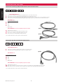
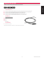
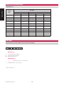
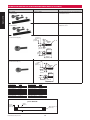
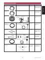
Temposonics®
Magnetostrictive Linear-Position Sensors
R
SENSORS
550929 B
Industrial Product Catalog Accessories
ACCESSORIES
Cable Length Limitations (Based on published Bus and Serial Communications Standards)
Apply good industry practices for long cable runs - keep cable away from high power AC lines and all motor drive cables.
R-Series Sensor Models
Maximum Cable
or Bus Length
Baud Rate
1.5 MBd
400 kBd
300 kBd
200 kBd
100 kBd
10 ft.
160 ft.
320 ft.
650 ft.
1300 ft.
(3 m)
(50 m)
(100 m)
(200 m)
(400 m)
R-Series CANbus
1.0 MBd
500 kBd
250 kBd
125 kBd
80 ft.
320 ft.
820 ft.
1640 ft.
(25 m)
(100 m)
(250 m)
(500 m)
R-Series DeviceNet
500 kBd
250 kBd
125 kBd
420 ft.
800 ft.
1730 ft.
(130 m)
(270 m)
(530 m)
12 MBd
1.5 MBd
500 kBd
187.5 kBd
≤93.75 kBd
330 ft.
650 ft.
1300 ft.
3280 ft.
3940 ft.
(100 m)
(200 m)
(400 m)
(1000 m)
(1200 m)
R-Series SSI
R-Series Profibus
G-Series Sensor Models
Maximum Cable Length
G-Series Analog
(Voltage or Current)
150 ft.
(45 m)
G-Series digital
(PWM or Start/Stop)
300 ft.
(90 m)
Note 1
G-Series Neuter
(Start/Stop output wired for square
wave neuter)
250 ft.
(75 m)
Note 2
Notes:
1. 300 feet maximum using the ± differential pair for the interrogation (Start) and
gate (Stop) signals.
2. 250 feet maximum using single-ended interrogation (Start) signal. The unused
interrogation signal MUST be terminated to ground at the control box.
1
Industrial Product Catalog 550929 B
Accessories
EXTENSION CABLE OPTIONS
EXTENSION CABLE OPTIONS - HOW TO ORDER
Standard 6-Pin connector type (D60) used with R-Series G-Series and E-Series Sensors
Accessories
D
1
D6 =
DA =
DJ =
DK =
2
3
4
5
6
7
8
SENSOR CONNECTION TYPE (1-2)
Female connector, (straight exit), and standard #530026 Cable (PVC jacket) for sensors with D6 or D60 connector
Female connector, (90° exit), and standard # 530026 cable (PVC jacket) for sensors with D6 or D60 connector.
Female connector, (straight exit) and # 530045 cable, (black polyurethane jacket for higher resistance to moisture and oil), for sensors with D6 or D60 connector.
Female connector, (90° exit), and #530045 cable, (black polyurethane jacket for higher resistance to moisture and oil), for sensors with D6 or D60 connector.
CABLE LENGTHS* (3-5)
For standard length cables up to 100 ft.
005 = 5 ft.
015 = 15 ft.
025 = 25 ft.
050 = 50 ft.
100 = 100 ft.
_ _ _ = Cable length (ft)*
Type DJ
CABLE TERMINATION (2 or 3 characters depending on option selected) (6-8)
P0 =
D6M =
D6 F =
DAF =
Pigtail connection, (no connector)
D6 male connector, (Straight exit). Only available with the D6 option above.
Female connector, (straight exit). Only available with the D6 option above.
Female connector, (90° exit). Only available with the DA option above.
Type DK
* Refer to “Cable Length Limitations” table on page 55 for maximum cable length.
6-Pin connector type (D63) used with R-Series Profibus Sensors
D
1
2
3
4
5
6
7
8
SENSOR CONNECTION TYPE (1-2)
DF =
DG =
Female connector, (straight exit), and #530040 cable for Profibus sensors with D63 connector
Female connector, (90° exit), and #530040 cable for Profibus sensors with D63 connector
Type DG
CABLE LENGTHS* (3-5)
For standard length cables up to 100 ft.
005 = 5 ft.
015 = 15 ft.
025 = 25 ft.
050 = 50 ft.
100 = 100 ft.
_ _ _ = Cable length (ft)*
CABLE TERMINATION (2 or 3 characters depending on option selected) (6-8)
P0 = Pigtail connection, (no connector)
DFM = Male connector, (Straight exit). For daisy-chain connections of Profibus sensors with D63 connector. Only available with the DF option above.
DGM = Male connector, (90° exit). For daisy-chain connections of Profibus sensors with D63 connector. Only available with the DG option above.
* Refer to “Cable Length Limitations” table on page 55 for maximum cable length.
Industrial Product Catalog 550929 B
2
EXTENSION CABLE OPTIONS - HOW TO ORDER
Standard 7-Pin DIN connector type (D70) used with R-Series SSI Sensors
D
P O
2
3
4
5
6
Accessories
1
7
SENSOR CONNECTION TYPE (1-2)
D7 =
DR =
DS =
DT =
DU =
DT =
Female connector, (straight exit), and #530029 cable (high performance shielding, orange polyurethane jacket), for SSI sensors with D70 connector.
Female connector, (90° exit), and #530029 cable (high performance shielding, orange polyurethane jacket), for SSI sensors with D70 connector.
Female connector, (straight exit) and standard #530026 cable, (PVC jacket), for SSI sensors with D70 connector.
Female connector, (90° exit), and standard #530026 cable, (PVC jacket), for SSI sensors with D70 connector.
Female connector, (straight exit), and #530045 cable, (black polyurethane jacket), for SSI sensors with D70 connector.
Female connector, (90° exit), and #530045 cable, (black polyurethane jacket), for SSI sensors with D70 connector.
CABLE LENGTHS* (3-5)
For standard length cables up to 100 ft.
005 = 5 ft.
015 = 15 ft.
025 = 25 ft.
050 = 50 ft.
100 = 100 ft.
_ _ _ = Cable length (ft)*
CABLE TERMINATION (6-7)
P0 =
Type D7
Pigtail connection, (no connector)
* Maximum cable length is dependent on the baud rate (refer to “Cable Length Limitations” table on page 55)
3
Industrial Product Catalog 550929 B
ADAPTER CABLE OPTIONS FOR REPLACING RETIRED SENSOR MODELS (Temposonics I, II & L-SERIES)
Product
Dimension
Application
Accessories
Used when replacing Tempo II and model LH sensors that have integral RB connectors
Part no: 253243, -1, -2
Female straight exit D6 to
male RB connection
adapter cables
Part no: 253244, -1, -2
Female straight exit D6 to male
RB connection adapter cables
-1
1 ft. cable length, standard
For G-Series analog output sensors
-2
1 ft. cable length, standard
For G-Series digital-pulse and neuter output sensors
-1
5 ft. cable length
For G-Series analog output sensors
-2
5 ft. cable length
For G-Series digital-pulse and neuter output sensors
Used when replacing Tempo II sensors that have integral RC connectors
Part no: 201612, -1, -2
Female straight exit D6 to male
RC connection adapter cables
-1
1 ft. cable length, standard
For G-Series analog output sensors.
-2
1 ft. cable length, standard
for G-Series digital-pulse and neuter output sensors.
Used when replacing model LH sensors that have integral or in-line 10-pin MS connectors
Part no: 253245, -1, -2
Female straight exit D6 to male
MS connection adapter cables
Part no: 253246, -1, -2
Female straight exit D6 to
male MS connection adapter
cables
-1
1 ft. cable length, standard
For G-Series analog output sensors.
-2
1 ft. cable length, standard
For G-Series digital-pulse and neuter output sensors.
-1
5 ft. cable length
For G-Series analog output sensors
-2
5 ft. cable length
For G-Series digital-pulse and neuter output sensors
Used when replacing Tempo II and model LH sensors that have in-line MS connectors wired for the R1, R2, or R3 connection types
Part no: 253245-3
Female straight exit D6 to
male MS (R1, R2, or R3
connection) adapter cables
Part no: 253246-3
Female straight exit D6 to
male MS (R1, R2, or R3
connection) adapter cables
Part no: 253302, -1, -2
Female straight exit D6 to
male MS (R1, R2, or R3
connection) adapter cables
Industrial Product Catalog 550929 B
-3
1 ft. cable length
For R3 connection using G-series digital-pulse output
sensors.
-3
5 ft. cable length
For R3 connection using G-series digital-pulse output
sensors.
-1
5 ft. cable length
For R1 (positive interrogation) connection using G-Series
sensors.
-2
5 ft. cable length
For R2 (negative interrogation) connection using G-Series
sensors.
4
ADAPTER CABLE OPTIONS FOR REPLACING RETIRED SENSOR MODELS (Temposonics I, II & L-SERIES)
Product
Dimension
Application
Part no: 253248, -1, -2
Female straight exit D6 to
male RG connection adapter
cables
Part no: 253315, -1, -2
Female straight exit D7 to
male RG connection adapter
cables
-1
1 ft. cable length, standard
For R-Series analog or G-Series analog and digital-pulse output
sensors
-2
5 ft. cable length
For R-Series analog or G-Series analog and digital-pulse output
sensors
-1
1 ft. cable length, standard
For R-Series SSI output sensors
-2
5 ft. cable length
For R-Series SSI output sensors
Used when replacing model LP sensors that have the integral C-style connector or in-line H or J style connectors
Part no: 253247, -1, -2, -3, -4
Female straight exit D6 to male AMP connection adapter cables.
-1
1 ft. cable length
For G-Series analog output sensors
-2
1 ft. cable length
For G-Series digital-pulse output sensors
-3
7 ft. cable length
For G-Series analog output sensors
-4
7 ft. cable length
For G-Series digital-pulse output sensors
Product
Dimension
Part no. 401327
Male RC to female RB
connector adapter.
6 in. overall length
Application
For retrofitting RC connection style Temposonics II or model
LH sensors
CONNECTORS (For Current Production Sensors)
Product
Dimension
Material
Application
5-pin style connectors
Part no. 370375
D51 Field-installable connector
55m m(2.2in.)
Female, straight exit, for Model R-Series
sensors with DeviceNet output
20mm
(0.8in.)
Part no. 370376
D51 Field-installable
connector
37 mm( 1.5in)
Female, 90° exit, for Model R-Series
sensors with DeviceNet output
41mm
(1.6in.)
5
Industrial Product Catalog 550929 B
Accessories
Used when replacing models LH, LP and R-Series sensors that have integral RG connectors
CONNECTORS (For Current Production Sensors)
Product
Dimension
Material
Application
Accessories
6-pin style connectors
Part no. 560700
D6 Field-installable
connector
54 mm
(2.13 in.)
Ø 18 mm
(0.71 in.)
Part no. 370372
D6 Field-installable
connector
54 mm
(2.13 in.)
Ø 18 mm
(0.71 in.)
Part no. 370423
D6 Field-installable connector
54 mm
(2.13 in.)
Ø 18 mm
(0.71 in.)
Part no. 370427
D6 Fieldinstallable
connector
54 mm
(2.13 in.)
Ø 18 mm
(0.71 in.)
Part no. 560778
D6 Fieldinstallable
connector
54 mm
(2.13 in.)
38 mm
(1.5 in.)
Ø 19.5 mm
(0.77 in.)
Part no. 370460
Profibus D6 Fieldinstallable connector
54 mm
(2.13 in.)
38 mm
(1.5 in.)
Ø 19.5 mm
(0.77 in.)
Part no. 252347*
Profibus bus
terminator
* was 370419
(STA09131H06)
48 mm
(1.88 in.)
Ø18 mm
(0.70 in.)
Housing: Zinc nickel
plated
Termination: Solder
Contact insert: Silver
plated
Cable clamp: PG7
Female, straight exit, mates
to D60 connection type on
R-Series, G-Series & E-Series
sensors with six conductor
cable (STC09131D)
Housing: Zinc nickel
plated
Termination: Solder
Contact insert: Silver
plated
Cable clamp: PG7
Male, straight exit
Housing: Zinc nickel
plated
Termination: Solder
Contact insert: Silver
plated
Cable clamp: PG9
Max. cable dia.: 8mm
Female, for Profibus sensors
w/PG9 strain relief (D63
connection type). Also used
to retrofit 10 conductor
Tempo II extension cables
(STC09131D06PG9)
Housing: Zinc nickel
plated
Termination: Solder
Contact insert: Silver
plated
Cable clamp: PG9
Max. cable dia.: 8mm
Male, for Profibus sensors
w/PG9 strain relief (D63
connection type)
(STC09131H06PG9)
Housing: Zinc nickel
plated
Termination: Solder
Contact insert: Silver
plated
Cable clamp: PG9,
M16
Max. cable dia.: 8 mm
Female, 90° exit, mates to
D60 & Profibus D63
connection type on R-Series,
G-Series & E-Series sensors
with six conductor cable
(STC09131-6)
Housing: Zinc nickel
plated
Termination: Solder
Contact insert: Silver
plated
Cable clamp: PG9
Max. cable dia.: 8mm
Male, 90° exit, for Profibus
sensors (D63 connection
type) (STC09131H06PG9)
Housing: Zinc nickel
plated
Termination: Solder
Contact insert: Silver
plated
For use with Model RH, RP &
RF sensors, Male connector
type
Housing: Zinc nickel
plated
Termination: Solder
Contact insert: Silver
plated
Cable clamp: PG7
Female, Straight exit, mates
to D70 connection type on
R-Series sensors. Connector
has PG7 size strain relief for
standard cable.
Housing: Zinc nickel
plated
Termination: Solder
Contact insert: Silver
plated
Cable clamp: PG9
Max. cable dia.: 8mm
Female, straight-exit, mates
to D7 connection type on
R-Series SSI sensors.
Connector has PG9 size
strain-relief for larger cable
size, (STC09131D07PG9)
Housing: Zinc nickel
plated
Termination: Solder
Contact insert: Silver
plated
Cable clamp: PG9, M16
Max. cable dia.: 8 mm
Female, 90° exit, mates to D70
connection type on
R-Series sensors
(STC09131-7)
7-pin style connectors
Part no. 560701
D7 Field-installable connector
54 mm
(2.13 in.)
Ø 18 mm
(0.71 in.)
Part no. 370516
D7 Field-installable
connector
54 mm
(2.13 in.)
Ø 18 mm
(0.71 in.)
Part no. 560779
D7 Field-installable
connector
54 mm
(2.13 in.)
38 mm
(1.5 in.)
Ø 19.5 mm
(0.77 in.)
Industrial Product Catalog 550929 B
6
CONNECTORS (For Retired Sensor Models)
Dimension
Material
Part no. 400755-3
RB/RC connector, Field-installable
Application
Female field-installable, mates
with sensor fitted with RB
connector or previous RC
design
64mm (2.5 in.)
27 mm
(1.1 in.)
Part no. 370486
RB connector
Male, field-installable
mates with
part no: 400755-3
64 mm (2.5 in.)
27 mm
(1.1 in.)
Part no. 401366
RG Field-installable connector
Female, straight exit
mates to RG connection type
on R-Series and L-Series
58 mm
(2.28 in.)
19 mm
(0.75 in.)
Part no. 370391
D8 Field-installable connector
54 mm
(2.13 in.)
Ø 18 mm
(0.71 in.)
7
Housing: Zinc nickel
plated
Termination: Solder
Contact insert: Silver
plated
Cable clamp: PG7
Female, straight exit, mates to
D80 connection type on
Model L Series
Industrial Product Catalog 550929 B
Accessories
Product
MAGNETS AND FLOATS
Product
Dimension
Material
Accessories
Part no. 201542-2
Standard ring magnet
4 Holes
each 4.3 mm dia. (0.17 in.)
90 º apart on 23.9 mm dia.
(0.94 in.)
ID: 13.5 mm (0.53 in.)
OD: 32.8 mm (1.29 in.)
Thickness: 7.9 mm (0.312 in
Part no. 201553
Large open-ring
magnet
1of2Holes
4.5mmdia.(0.177in.)
120º apart on 41.3 mm d
(1.625in.)
11.2mm(0.44in.)opening
90 Cu t-out
Application
Composite PA-FerriteGF20
Weight: Approx. 14g
Operating temperature:
-40 to +100°C
For Model RH, GH
PA 66-GF30
Magnet slugs potted
with epoxy
Weight: Approx. 26g
Operating temperature:
-40 to +75°C
For Model RH, GH
PA 66-GF30
Magnet slugs potted
with epoxy
Weight: Approx. 35g
Operating temperature:
-40 to +75°C
For Model RH, GH
I.D.:15.9mm(0.625in.)
O.D.:63.25mm(2.49in.)
Thickness:9.5mm(0.375in.)
Part no. 201554
Large ring magnet
1of4Holes
each4.6mmdia.(0.182in.)
90 ap arton41.3mmdia.
(1.625in.)
I.D.:19.05mm(0.75in.)
O.D.:63.25mm(2.49in.)
Thickness:9.5mm(0.375in.)
Part no. 251298-2
Bar Magnet
For Model RH, RP, GH, GP,
EP
28 mm
(1.10 in.)
19 mm
(0.75 in.)
7.6 mm
(0.30 in.)
S
Stainless-steel plate
(bonded to magnet,
both sides)
Part no. 251416-2
Standard open ring
magnet
N
20 mm
(0.80 in.)
13 mm
(0.52 in.)
2 Holes
each 4.3 mm dia. (0.17 in.)
on 23.9 mm dia. (0.94 in.)
60 °
24.6 mm
(0.97 in.)
14 mm
(0.57 in.)
20.7 mm
(0.81 in.)
Part no. 251447
Magnet float
For Model RP, RH, GH, GP,
EP
316L Stainless steel
Density: 720 kg/m3
Max. Pressure: 870 psi
Weight: 42 ± 3g
For Model RH, GH
GFK, Magnet hard
ferrite
Weight: Approx. 30g
Operating temperature:
-40 to +75°C
For Model RP, GP, EP
GFK, magnet hard
ferrite
Weight: Approx. 30g
Operating temperature:
-40 to 75° C
For Model RP, GP, EP
Similar to (252182) but with
extra length on the
ball-jointed arm
ID: 13.5 mm (0.53 in.)
OD: 32.8 mm (1.29 in.)
Thickness: 7.9 mm (0.312 in.)
14 mm (0.55 in.)
Min. ID
51 mm (2.0 in.)
Spherical OD
53 mm
(2.09 in.)
Composite PA-FerriteGF20
Weight: Approx. 11g
Operating temperature:
-40 to +100°C
3.4 mm (0.134 in.)
Specific Gravity: 0.70 approx.
Pressure: 870 psi max.
Part no. 252182
Captive-sliding magnet
43 mm
(1.69 in.)
14 mm
(0.55 in.)
Rotation:
Vertical: 18°
Horizontal: 360°
Ball-jointed arm,
M5 thread
20 mm
(0.79 in.)
24 mm
(0.95 in.)
40 mm
(1.58 in.)
Part no. 252183
Captive-sliding
magnet
24 mm
(0.94 in.)
43 mm
(1.69 in.)
20 mm
(0.79 in.)
Rotation:
Vertical: 18°
Horizontal: 360°
Ball-jointed arm,
M5 thread
24 mm
(0.95 in.)
40 mm
(1.58 in.)
Industrial Product Catalog 550929 B
8
MAGNETS AND FLOATS
Part no. 252184
Captive-sliding magnet
Dimension
57 mm
(2.24 in.)
14 mm
(0.55 in.)
18° rotation
24 mm
(0.95 in.)
Ball-jointed arm,
M5 thread
9 mm
(0.35 in.)
Part no. 252887
Block magnet type L
Material
GFK, magnet hard
ferrite
Weight: Approx. 30g
Operating temperature:
-40 to 75° C
Application
For Model RP, GP, EP
40 mm
(1.58 in.)
For Model EP, EP2
19.5 mm
(0.77 in.)
6 mm (0.24 in.)
20 mm (0.79 in.)
11 mm (0.43 in.)
O 4.3 mm
(0.17 in.)
31 mm
(1.22 in.)
13.5 mm
(0.53 in.)
Part no. 400533
Small ring magnet
I.D. 13.5 mm (0.53 in.)
O.D. 25.4 mm (1.0 in.)
Thickness: 7.9 mm (0.312 in.)
Part no. 400633
Magnet spacer
4 Holes
each 3.9 mm O.D. (0.15 in.)
90° apart on 23.9 mm O.D. (0.94 in.)
Composite: PA-Ferrite
Weight: Approx. 10g
Operating temperature:
-40 to +100° C
For Model RH, GH
Aluminum
For Model RH, GH.
Non-ferrous spacer for use
with standard ring magnet
(201542-2)
Surface PA coated
Weight: Approx. 5g
Operating temperature:
-40 to +100° C
For Model RH, GH.
Not for multi-position
measurement. Resolution
min. 10 µm
Composite: PA-Ferrite
Operating temperature:
-40 to +100° C
For Model RH, GH
Composite: PA-Ferrite
Operating temperature:
-40 to +100° C
For Model RH, GH
I.D. 14.3 mm (0.56 in.)
O.D. 31.8 mm (1.25 in.)
Thickness: 3.2 mm (0.125 in.)
Part no. 401032
Small ring magnet
I.D. 13.5 mm (0.532 in.)
O.D. 17.4 mm (0.685 in.)
Thickness: 7.9 mm (0.312 in.)
(For use with strokes
≤1525 mm or 60 in.)
Part no. 401467
Large ring magnet
3.4 mm
(0.13 in.)
A
30 mm
(1.18 in.)
24 mm
A (0.95 in.)
Part no. 401468
Large ring magnet
11 mm (0.43 in.)
A
O.D. 38.1 mm
(1.5 in.)
.
A
9
I.D. 33 mm
(1.3 in.)
Industrial Product Catalog 550929 B
Accessories
Product
MAGNETS, FLOATS, AND PRESSURE HOUSING
Compatibility Chart
Accessories
Sensor Model
Magnet
Part no.
Rod-style
Profile-style
RP
GP
EP
•
•
•
•
•
•
•
•
•
•
•
252182
•
•
•
252183
•
•
•
252184
•
•
•
RH
GH
201542-2
•
•
201553
•
•
201554
•
•
201298-2
•
251416-2
251447 (float)
400533
•
•
401032
•
•
401467
•
•
401468
•
•
HOW TO ORDER
Pressure Housing (for use with Temposonics sensor models GH and RH only)
H H
1
2
3
4
5
6
7
8
HOUSING STYLE (3)
T=
S=
M=
US customary threads, raised-faced hex
US customary threads, flat-faced hex
Metric threads, flat-faced hex
STROKE LENGTH (4-8)*
Inches and tenths (Encode in 0.1 in. increments)
or
_ _ _ _ M =Millimeters (Encode in 5 mm increments)
___._U=
* Limited to 1825 mm (72 in.)
Industrial Product Catalog 550929 B
10
MOUNTING FEET AND T-SLOT NUT
Part no. 400802
Mounting feet,
standard
Dimension
0.213 in. dia.
through 4 holes
Material
9.1 mm
(0.36 in.)
27.9 mm
(1.1 in.)
1.9 mm
(0.075 in.)
Application
304 Stainless steel
For use with Model RP, GP, EP
and ER sensors.
Stainless steel with
nylon washers and
cloth tape on bottom
For use with Model RP, GP,
and EP sensors. Provides
electrical and mechanical
isolation.
M5 thread
Nut for mounting RP and GP
sensors.
9.1 mm
(0.36 in.)
50 mm (1.97 in.)
304 SST
68 mm
(2.68 in)
Width = 14.5 mm (0.57 in.)
Part no. 252004
Mounting feet,
insulated
5 mm (0.196 in.) I.D.
9 mm
(0.36 in.)
28 mm
(1.1 in.)
2 mm
(0.08 in.)
9 mm
(0.36 in.)
50 mm (1.97 in.)
68 mm
(2.68 in)
Width = 14.5 mm (0.57 in.)
Part no. 401602
Base channel T-slot nut
5 mm (0.20 in.)
T-Slot nut, M5 thread
(optional, sold separately)
MECHANICAL END CONNECTORS (FOR USE WITH TEMPOSONICS SENSOR MODELS RP, GP, EP AND ER)
Product
Dimension
Part no. 401603
Joint-rod sleeve
(1 in.)
22 mm
(0.87 in.)
Material
Application
For use with captive-sliding
magnets
9 mm
(0.35 in.)
27 mm
(1.06 in.)
14 mm
(0.55 in.)
M5 threads
Rotation: 18˚
allowable
Part no.
401913*
Ball-jointed
arm, straight
22 mm
(0.87 in.)
M5 inside
thread
(1)
(2)
For use with captive-sliding
magnets
9 mm
(0.35 in.)
27 mm
(1.06 in.)
14 mm
(0.55 in.)
M5 threads
Rotation: 18˚
allowable
Part no. 251975
Stud end attachment
(1)
(2)
M5 inside
thread
For use with Model ER
sensors
53.3 mm
(210 in.)
Threaded Rod
(1/4 - 28 UNF)
1/4 in. Jam Nut
Mounting Hardware
Includes: 1/4 in. hex nuts (2 pcs.)
and washer
Part no. 402849
Thread adapter,
10-32 male to M5 female
Stainless Steel
Lock Washer
10-32 UNF - 2A
M5 x 0.8
8 mm
(0.31 in.)
12.7 mm
(0.50 in.)
9 mm
(0.35 in.)
This part can be
used with Models EP,
GP, or RP captive-sliding
magnets when
retrofitting old LPS
model sensors that have
the old 252052 captivesliding magnet (with
#10-32 male threads).
12.7 mm
(0.50 in.)
11
Industrial Product Catalog 550929 B
Accessories
Product
MECHANICAL END CONNECTORS (FOR USE WITH TEMPOSONICS SENSOR MODELS RP, GP, EP AND ER)
Accessories
Product
Dimension
Application
Part no. 253346
Rod end kit (English)
See Part no. 560444
Male 1/4-28 rod ends (2 pieces), plus special wrench for
use with Model ER sensors.
Part no. 253347
Rod end kit (Metric)
See Part no. 561255
Male M6 rod ends (2pieces), plus special wrench for use
with Model ER sensors.
Part no. 560444
Rod end attachment (English)
Male 1/4-28 for use with Model ER sensors.
7.2 mm
(0.28 in.)
9.5 mm
(0.37 in.)
16° Misalign
Angle
6.0 mm
(0.24 in.)
1/4 - 28
25.4 mm
(1.0 in.)
18.8 mm
(0.74 in.)
40.0 mm
(1.57 in.)
Part no. 561255
Rod end attachment (Metric)
Male M6 for use with Model ER sensors.
7.0 mm
(0.28 in.)
9.0 mm
(0.35 in.)
16° Misalign
Angle
6.0 mm
(0.24 in.)
M6
22 mm
(0.87 in.)
19.0 mm
(0.75 in.)
36.0 mm
(1.42 in.)
Extension rod lengths
60.3 mm (2.375 in.)
85.7 mm (3.375 in.)
111.1 mm (4.375 in.)
161.9 mm (6.375 in.)
187.3 mm (7.375 in.)
212.7 mm (8.375 in.)
238.1 mm (9.375 in.)
263.5 mm (10.375 in.)
314.3 mm (12.375 in.)
365.1 mm (14.375 in.)
Part no.
401768-2
401768-3
401768-4
401768-6
401768-7
401768-8
401768-9
401768-10
401768-12
401768-14
Extension rod lengths
390.5 mm (15.375 in.)
466.7 mm (18.375 in.)
517.5 mm (20.375 in.)
542.9 mm (21.375 in.)
619.1 mm (24.375 in.)
771.5 mm (30.375 in.)
923.9 mm (36.375 in.)
1076.3 mm (42.375 in.)
1228.7 mm (48.375 in.)
1533.5 mm (60.375 in.)
Part no.
401768-15
401768-18
401768-20
401768-21
401768-24
401768-30
401768-36
401768-42
401768-48
401768-60
Extension rod
part no. 401768-XX
15.2 mm
(0.60 in.)
(both ends)
Industrial Product Catalog 550929 B
9.5 mm
(0.375 in.)
M5-0.8 thread bore
(both ends)
12
MISCELLANEOUS INSTALLATION HARDWARE
Dimension
Material
Application
Part no. 500015
Hex jam-nut
3/4-16 in. UNC
Stainless steel, nylon
insert
3/4-16 UNF Nylon insert
locknut for use with model
RH and GH sensors with
style “T” or “S” housings.
Part no. 500018
Hex jam-nut
M18 x 1.5 threads
Stainless steel
M18 x 1.5 nut for use with
models RH and GH sensors
with style “M” housing.
304 stainless steel
For use with GH and RH
pressure housings and float
251447.
Fluoroelastomer 75 ±
5 durometer
Spare, for use with rod-style
sensor Models RH and GH.
With style “T” or “S”
housing.
#6-32x7/8
Stainless steel
Used to mount standard ring
magnet part no: 201542-2
(4 required) or open ring
magnet part no: 251416-2
(2 required).
Part no. 560777
Collar
27 mm
(1.06 in.) OD
10 mm
(0.4 in.) ID
5 mm
(0.2 in.)
4 mm
8-32 threads (0.16 in.)
9 mm
8 mm
(0.34 in.)
(0.31 in.)
Part no. 560315
O-Ring, for US
customary flange
with 3/4-16 UNF threads
16.36 mm ± 0.23 mm
(0.644 in. ± 0.009 in.) ID
2.21 mm ± 0.08 mm
(0.087 in. ± 0.003 in.)
Part no. 560357
Magnet mounting
screws
Part no. 402617
Electronics
housing screw
Used to install newer sensor
cartridges (GHB and RHB
models) into the old LH or
old RH sensor pressure
housings (2 required).
59.7 mm
(2.35 in.)
2.5 mm
Hex socket
8-32 UNC - 2A
Part no. 401133
0-Ring, for metric
flange with M18 x 1.5
threads.
15.3 mm ± 0.2 mm
(0.60 in. ± 0.01 in.) ID
2.2 mm ± 0.08 mm
(0.09 in. ± 0.003 in.)
Part no. 252916
Profibus filter box
Bus
Bus
Fluoroelastomer 75 ±
5 durometer
Spare, for use with rod-style
sensor Models RH and GH
with style “M’ housing.
Dimensions: 80 mm
(3.15 in.) long x 75
mm (2.95 in.) wide x
58 mm (2.28 in.)
deep.
The box is used for EMCconformal feeding of 24 Vdc
supply voltage into the
Profibus-DP hybrid cable.
24 Vdc
13
Industrial Product Catalog 550929 B
Accessories
Product
SENSOR DISPLAY
Product
Dimension
Accessories
Part no. 251153
Temposonics Display Unit
(TDU-200)*
Application
Meter for use with Start/Stop sensors
only.
109.5 mm
(4.31 in.)
6.98 mm
(0.275 in.)
45.21 mm
(1.78 in.)
SIDE
48 mm
(1.89 in.)
FRONT
48 mm
(1.89 in.)
96 mm
(3.78 in.)
91.44 mm
(3.6 in.)
Note:
*Product Specification 550178 and User’s Manual 550260.
BACK
45.21 mm
(1.78 in.)
POWER SUPPLY
Product
Dimension
Part no: 380009
Sensor power supply
100 mm x 165 mm x 50 mm.
Application
Standard power supply (110 Vac to 24
Vdc/ 0.5 A) for use with sensors and
interface products.
SENSOR PROGRAMMING
Product
Part no. 253124
R-Series analog hand-held programmer
Sensor
Application
24 V
For adjusting null (setpoint 1) and span (setpoint 2) on R-Series analog
sensors, (for single magnet versions only).
Part no. 253408
R-Series analog cabinet programmer
For adjusting null (setpoint 1) and span (setpoint 2) on R-Series analog
sensors, (for single magnet versions only). The programmer is designed
for snap-in mounting on standard 35 mm DIN rail. A “program/run” switch
allows the programmer to be permanately wired inside the control cabinet.
Part no. 253309
R-Series analog PC programming kit
Interface converter box, power supply, PC software and cabling.
Part no. 253310
R-Series SSI PC programming kit
Interface converter box, power supply, PC software and cabling.
Part no. 252173-D63
R-Series Profibus node address
programmer
For field address programming of R-Series Profibus output.
Part no.252173-D53
R-Series Profibus programming accessories
For field address programming of R-Series Profibus output.
Part no. 252382-D62
R-Series CANbus programming accessories
For field address programming of R-Series CANopen sensors.
Industrial Product Catalog 550929 B
14
SENSOR PROGRAMMING
Application
Part no. 253294
G-Series analog hand-held programmer
For adjusting null (setpoint 1) and span (setpoint 2) on G-Series analog
sensors.
Part no. 380078
G-Series infrared setpoint programmer
For adjusting null (setpoint 1) and span (setpoint 2) on G-Series analog
sensors.
Part no. 253311
G-Series analog PC programming kit
Interface converter box, power supply, PC software and cabling.
Part no. 253312
G-Series digital pulse PC programming kit
Interface converter box, power supply, PC software and cabling.
Part no. 401727
Profibus master simulator
Can be used to check the sensors functions and to change the slave
address. Allows the magnet positions and diagnostic data to be read.
FIELD SETUP SOFTWARE
Product
Application
Part no. 551033
G-Series documentation and software CD
Includes G-Series PC setup software (part no: 625060)* G-Series Palm OS
software (part no: 625061)*, G-Series User’s Manual (part no: 550966)
and additional documentation.
Part no. 551052
R-Series documentation and software CD
Includes R-Series PC setup software (part no: 625064)*, parameter files
and product documentation.
Note:
* Download software from our website (www.mtssensors.com)
15
Industrial Product Catalog 550929 B
Accessories
Product
Part Number: 09-06 550929 Revision B
MTS and Temposonics are registered trademarks of MTS Systems Corporation.
All other trademarks are the property of their respective owners.
All Temposonics sensors are covered by US patent number 5,545,984. Additional patents are pending.
Printed in USA. Copyright © 2006 MTS Systems Corporation. All Rights Reserved.
R
SENSORS
UNITED STATES
GERMANY
JAPAN
MTS Systems Corporation
Sensors Division
3001 Sheldon Drive
Cary, NC 27513
Tel: (800) 633-7609
Fax: (919) 677-0200
(800) 498-4442
www.mtssensors.com
[email protected]
MTS Sensor Technologie
GmbH & Co. KG
Auf dem Schüffel 9
D - 58513 Lüdenscheid
Tel: +49 / 23 51 / 95 87-0
Fax: +49 / 23 51 / 56 491
www.mtssensor.de
[email protected]
MTS Sensors Technology
Corporation
Ushikubo Bldg.
737 Aihara-cho, Machida-shi
Tokyo 194-0211, Japan
Tel: + 81 (42) 775 / 3838
Fax:+ 81 (42) 775 / 5516
www.mtssensor.co.jp
[email protected]