1
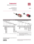
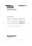
Temposonics®
Magnetostrictive Position Sensors
R
SENSORS
G-Series Linear Position Sensor
Analog and Digital Pulse Outputs
550966 B
User’s Manual
Temposonics Model GP
Figure 1 - G-Series Connector Pin-Outs
6
3
1
Connection Options
Temposonics G-Series sensors are preconfigured at the factory by model
code designation. If needed, a variety of retrofit and replacement options are
available to provide direct backwards compatibility for your application.
4
5
Temposonics Model GH
G-Series sensor connection options:
2
Integral Connector (D6 Male)
(As viewed from end of sensor)
Option D60
• Integral 6-pin DIN male connector, (option “D60”)
• Integral cable with pigtail end, standard type (option “R _ _” ), and
heavy duty type (option “F _ _” )
• Integral cable with in-line RB type male connector (option “RB _” )
• Integral cable with in-line MS type male connector (option “FM _” )
Depending on the sensor output selected (Analog, Digital Pulse, or Neuter )
the different wiring required for the applicable combinations are shown in
Tables 1-3. Pin-outs for the above connector types are illustrated in Figure 1.
1
9
10
7
5
8
3
2
Notices used in this user’s manual
6 4
Notes:
These notices provide important tips, guidance or advice.
In-line RB connector
Option RB _
Caution:
These notices indicate situations that can be potentially hazardous to you. A caution
notice is placed just before a description of a potentially hazardous procedure, step or
situation.
A
H
B
G
F
Important:
These notices provide information that might help you avoid inconvenient or problem
situations.
J C
K
E
D
In-line MS connector
Option FM _
All specifications are subject to change. Please contact MTS for specifications that are critical
to your needs. For additional information go to www.mtssensors.com.
G-Series Wiring/Connections
Table 1 - Analog Output Connections (Voltage or Current)
Integral cable
wire color
R_ _ or F_ _
Integral
connector
D60 pin no.
In-line
connector
FM_ pin no.
In-line
connector
RB_ pin no.
Notes:
Function (Note 1)
Gray
1
4
D
0 to 10, -10 to +10 Vdc, or
4 to 20 mA, 0 to 20 mA
or reverse acting (note 2):
10 to 0, +10 to -10 Vdc, or
20 to 4 mA, 20 to 0 mA
Pink
2
3
C
Return for pin 1
Yellow
3
7
G
Programming (RS-485 +)
Green
4
8
H
Programming (RS-485 -)
Red or Brown
5
5
E
Supply voltage (+Vdc)
White
6
1
A
DC ground (for supply)
---
---
2
B
No connection
---
---
6
F
No connection
---
---
9
J
No connection
---
---
10
K
No connection
1. The format used to show the voltage
and current output range is: [Value at
Null (Setpoint 1)] to [Value at Span
(Setpoint 2)]. Not all of the available
outputs ranges for voltage are shown.
2. If the G-Series sensor is replacing a
L-Series sensor where the reverse
acting outputs are being used then
the wire connections must be changed
at the controller. Refer to G-Series
Cross Reference, part no. 550967 for
details.
Table 2 - Digital Pulse Output Connections (Start/Stop or PWM)
Integral cable
wire color
R_ _ or F_ _
Integral
connector
D60 pin no.
In-line
connector
RB_ pin no.
In-line
connector
FM_pin no
Gray
1
3
C
(-) Gate for PWM
(-) Stop for Start/Stop, or
Programming (RS-422 TX -)
Pink
2
4
(and 8)
D
(+) Gate for PWM
(+) Stop for Start/Stop, or
Programming (RS-422 TX +)
Yellow
3
9
J
(+) Interrogation for PWM (see note)
(+) Start for Start/Stop, or
Programming (RS-422 RX +)
Green
4
10
K
(-) Interrogation for PWM (see note)
(-) Start for Start/Stop, or
Programming (RS-422 RX -)
Red or Brown
5
5
E
Supply voltage (+Vdc)
White
6
1
A
DC ground (for supply)
---
---
2
B
No connection
---
---
6
F
No connection
---
---
7
G
No connection
---
---
---
H
No connection
Note:
Function
When using PWM output with internal
interrogation both of the interrogation
input signals are not used, and can be
left unconnected or connected to
ground.
Table 3 - Square Wave Neuter Output Connections
The G-Series square wave neuter
output is provided for backwards
compatibility to replace Tempo I,
Tempo II, and L-Series sensors.
These sensors have the neuter
output option for connection to the
Analog Output Module (AOM),
Digital Interface Box (DIB), or to
custom interfaces/controllers.
Reference the G-Series Cross
Reference, part no. 550967, for
additional neuter output connection
information, including adapter
cables and field-installed connectors.
Notes:
Integral cable
wire color
R_ _ or F_ _
Integral
connector
D60 pin no.
In-line
connector
RB_ pin No.
Gray
1
3
(-) Stop (note 2), or
Programming (RS-422 TX -)
Pink
2
8
(and 4)
(+) Stop (Compatible
Neuter Output Pulse), or
Programming (RS-422 TX +)
Yellow
3
9
(+) Start (note 3, 4), or
Programming (RS-422 RX +)
Green
4
10
(-) Start (note 3, 4), or
Programming (RS-422 RX -)
Red or Brown
5
5
Supply voltage (+Vdc)
White
6
1
DC ground (for supply)
---
---
2
No connection
---
---
6
No connection
---
---
7 (note 5)
No connection
Function
(see note 1)
2
1. The “(+) Stop” output is used for a compatible square wave
neuter signal.
2. The G-Series output signal, “(-) Stop” is not used when
providing the backwards-compatible neuter type connection.
However, this signal wire / connector pin is used for “RS-422
TX-” during serial programming of the sensor. When the
sensor output is active, (not in programming mode), this signal
must be left unconnected to allow the proper neuter type
output.
3. When connecting to an Analog Output Module (AOM), or to a
Digital Interface Box (DIB), or to a custom interface/controller
that requires single-ended interrogation, always connect the
unused interrogation lead, “(+) Start” or “(-) Start”, to ground at
the AOM/DIB/Controller.
4. For improved noise rejection when using external interrogation
use the positive and negative interrogation signals, “(+) Start”
and “(-) Start”, to provide differential inputs to the sensor.
5. If pin 7 was originally used as DC ground for the Tempo II or
L-Series sensor being replaced then the DC ground connection
at the controller must be changed to use pin 1.
Programming & Diagnostics
G-Series LED Diagnostic Codes
G-Series sensor red and green LEDs are intended to provide basic visual feedback for normal sensor operation and troubleshooting. These LEDs are located
at the end of the sensor where the cable or connector is terminated. The green LED is used to indicate power applied and normal operation while the red LED
is used to indicate programming mode operation and errors. See Table 4 for normal operation and diagnostic LED codes.
Table 4 - G-Series LED Codes
Green
Red
Description
OFF
OFF
No power to sensor
OFF
ON
Self-diagnostic error
OFF
FLASHING
Infrared programming mode (PDA or IR setpoint programmer)
ON
OFF
Normal sensor function
ON
ON
Magnet not detected
ON
FLASHING
Missing (external) interrogation
FLASHING
OFF
Serial programming mode (PC setup software)
FLASHING
ON
Magnet signal weak
FLASHING
FLASHING
Power out of range (high or low) 3
1
2
Notes:
1 Missing (external) interrogation - If the sensor is a Start/Stop or PWM output style, with external interrogation,
then no interrogation signal has been received over the timeout period. Standard timeout is 0.5 seconds.
2 Magnet signal weak - Sensor is still operating, but magnet placement should be corrected to assure continued
operation. (May also indicate other problems that cause weak magnet return signals.)
3 Power out of range (high or low) - Supply voltage is nearly beyond the acceptable limits. If voltage is low the
sensor is still operating, but the supply voltage should be corrected to assure continued operation. If the
voltage is high the sensor is still operating, but the sensor’s over-voltage protection may engage, powering off
the sensor temporarily. The over-voltage should be corrected to assure continued operation and avoid
possible permanent damage.
G-Series External Programming and Diagnostics
Temposonics G-Series sensors are preconfigured at the factory by model code designation. In many applications, the G-Series field programming tools are
not necessary to obtain the desired sensor operation. The three programming tools are described in Table 5.
Table 5 - G-Series Programming & Diagnostic Tools
Digital-pulse outputs
Analog output
Programming & diagnostic tool
Programming
Diagnostics
Programming
Diagnostics
PC setup software
(part no. 625060)
Output parameters
Status variables
Output parameters
Status variables
PDA Palm OS software
(part no. 625061)
Output parameters
Status variables
NA
NA
IR Setpoint programmer
(part no. 380077)
NA
NA
Adjust null and span setpoints
NA
Caution:
Prior to initiating G-Series programming, it is critical that the user ensures that taking the sensor out of normal operating mode or modifying the sensor’s operating parameters will not cause harm to the process utilizing the G-Series sensor feedback, nor to any persons associated.
Important Note:
Use of G-Series programming tools requires that users operate the sensors in one of the programming modes (serial or infrared) instead of the normal operational mode,
(i.e. sensor providing position feedback). It is critical to understand that the user must switch between programming mode and normal operation mode – programming
and normal operation cannot occur simultaneously. The only exception is that the G-Series Analog output sensor will still transmit its analog output over the output pins
(wires) while in programming mode. This is necessary to enable users to adjust the analog null and span setpoints.
3
G-Series PC Setup Software
The G-Series PC setup software is intended to provide the most comprehensive sensor monitoring and programming user interface available for this
product line. Using this program, it is possible to modify sensor parameters
and view important diagnostic outputs. The Help file within the setup program contains details on program operation, sensor programming and diagnostic features.
Figure 2 - Hardware Connections for the PC Setup Software
PN
P/N380077
380077
Converter
Converter
G-Series
G-Seriessensor
Sensor
Sensor
Sensor
Cable
cable
Equipment needed:
Windows
Windows
PC
PC
DB9 Serial
Serial
DB9
cable
Cable
Hardware Setup Notes:
• G-Series model sensor
• Windows PC with G-Series Setup software installed (see below)
• RS-232 to RS-422 or RS-485 serial interface converter (part no.
380077)
• Two AAA batteries for the serial interface converter
• Dual DB9 connector serial communication cable (male to female)
• Sensor power supply (+20.4 to +28.8 Vdc for sensor input voltage
option 1, or +9 to +23 Vdc for option 2)
• Mating cable for sensor (if necessary)
1.
A converter is required to communicate via the PCs serial (RS-232) port.
The serial interface converter must be configured for RS-232 to RS-422
communication for the Digital Pulse output sensors, or for RS-232 to RS-485
communication for the Analog output sensors.
• Digital-pulse output sensors - Set the dipswitches on the top of the converter such
that “422” and “Echo On” are selected for full duplex RS-232 to RS-422
communication.
• Analog output sensors - Set the dipswitches such that “485” and “Echo Off” are
selected for half-duplex RS-232 to RS-485 communication.
2. Connect the DB9 communication cable from the PC to the serial interface converter.
3. Make sure sensor is NOT connected to the control or sensor interface. Connect
sensor and converter as shown in Table 6 below.
4. Serial PC communication can only be accomplished if the sensor is powered.
Before applying power to the sensor make sure that the appropriate
power source and ground are connected as indicated in Tables 1-3 on page 2.
The G-Series Setup program is installed by first running the SETUP.EXE file
located on the “G-Series Documentation and Software” CD ROM (part no.
550971). This software can also be downloaded from
http://www.products.mtslinearsensors.com.
Table 6 - G-Series to Serial Interface Converter Wiring
Function Digital-pulse outputs
PN 380077 Converter
Set for RS-422
Function Analog outputs
PN 380077 Converter
Set for RS-485
Gray
(-) Gate for PWM
(-) Stop for Start/Stop or
Programming (RS-422)
(-) Receive
“RD A (-)”
Analog output
No connection
2
Pink
(+) Gate for PWM
(+) Stop for Start/Stop or
Programming (RS-422)
(+) Receive
“RD B (+)”
Return for pin 1
No connection
3
Yellow
(+) Interrogation for PWM
(+) Start for Start/Stop or
Programming (RS-422)
(+) Transmit
“TD B (+)”
Programming
(RS-485+)
(+) Txd/Rxd “TD B (+)”
[Add jumper to “RD B (+)”]
4
Green
(-) Interrogation for PWM
(-) Start for Start/Stop or
Programming (RS-422)
(-) Transmit
“TD A (-)”
Programming
(RS-485-)
(-) Txd/Rxd “TD A (-)”
[Add jumper to “RD A (-)”]
5
Red or Brown
Supply voltage (+Vdc)
connect to power supply
No connection
on converter box
Supply voltage (+Vdc)
connect to power supply
No connection
on converter box
6
White
DC ground
connect to power supply
No connection
on converter box
DC ground
connect to power supply
No connection
on converter box
D60
pin no.
Wire color
1
Establishing PC Serial Communication
Caution:
Prior to initiating G-Series programming, it is critical that the user ensures that taking the sensor out of normal operating
mode or modifying the sensor’s operating parameters will not cause harm to the process utilizing the G-Series sensor feedback, nor to any persons associated.
Complete the following steps to establish PC serial communication:
1.
Turn sensor power ON. Without prompting from the PC Setup program, the sensor will operate normally and the LED display will indicate the
appropriate normal operation (see LED Codes, Table 4 on page 3).
2.
With the sensor powered, execute the G-Series Setup program; click G-Series Field Setup shortcut on your desktop or in the “MTS Sensors” Startup
menu). If the serial port detected is correct, the program will automatically initiate serial (PC) programming mode and the sensor LEDs
should flash GREEN only. If there is a communications error, a dialog will appear giving you the options to “Abort”, “Retry” or “Ignore” the error. If the
user is confident the wiring and power to the sensor are correct, click the Ignore button and the correct communications port from the dialog that
immediately follows. This dialog can also be accessed by selecting Communications on the main menu bar and then clicking on Select COM port ….
3.
Normal sensor operation is resumed by either shutting down the setup program or by cycling power to the sensor.
4.
Note that normal operation mode will occur when sensor power is cycled even when the G-Series setup program is running. The program must
prompt the sensor before programming mode is initiated. This occurs when the program is first executed or by selecting the Click Here to Refresh
Data at the bottom of the page or by pressing F5.
Refer to the G-Series PC setup software Help file for details on advanced programming and diagnostic features.
4
Programming & Diagnostics Using a PDA - G-Series Digital Pulse Output Sensors Only.
Using the G-Series infrared (IR) interface, users can program G-Series
digital-pulse sensors using a Personal Digital Assistant (PDA). The PDA
interface can also be used as a monitor for position feedback as well as
diagnostics.
Software can be found on “G-Series Documentation and Software” CD ROM
(part no. 550971) or downloaded from
http://www.products.mtslinearsensors.com. This software is compatible
with Palm OS version 3.3 and above, with these Palm models only: Palm
III, IIIc, V, m100, m130, and Zire. To load the software to your PDA, select
the program for installation and synchronize the PDA with your PC.
Required Equipment:
• G-Series model sensor
• Mating cable for sensor (if necessary)
• PalmTM OS based PDA and G-Series PDA configuration software
installed (see below)
• Sensor power supply (+20.4 to +28.8 Vdc for input voltage option 1, and
+9 to +23 Vdc for option 2)
Hardware Setup Notes:
1. Make sure sensor is NOT connected to the control or sensor interface.
2. Do not apply power to the sensor yet. However, make sure that the
appropriate power source and ground connections are correct as
indicated in Tables 2 or 3 on page 2.
The required software file for G-Series PDA programming is named
MTS_GSeries.prc.
Establishing PDA Communications
Caution:
Prior to initiating G-Series programming, it is critical that the user ensures that taking the sensor out of normal operating mode or
modifying the sensor’s operating parameters will not cause harm to the process utilizing the G-Series sensor feedback, nor to any persons
associated.
Use of the G-Series IR programming tools requires a clear path from the
programming device to the sensor LEDs. Depending on the PDA device
used, IR communication with the sensor may be limited to 3 inches (75 mm)
from the LED window.
1.
Turn the PDA on, (power should not yet be applied to the sensor).
Select MTS G-Series from the main PDA menu.
2.
Align the IR window of the PDA device with the LED window of the
sensor as shown in Figure 3 below. Select Begin Prog then
immediately apply power to the sensor. The LED on the sensor will
flash red only when IR communications is established within the 5
seconds of applying power to the sensor (see Figure 3 below).
3. If IR communication is not established before the timeout period, simply
power the sensor down and begin step 2 again.
Note:
Once the PDA IR “Begin Program” input is received, the sensor will enter
and remain in program mode until this mode is exited or the sensor power
is cycled.
Figure 3 - Establishing PDA Communications
Sensor LEDs
IR signal
5
Programming & Diagnostics Using a PDA - G-Series Digital Pulse Output Sensors Only.
Reading Sensor Parameters (See Figure 4)
Using the PDA configuration program it is possible to read the sensor
parameters listed in Appendix A on page 8. To view these parameters or status variables, in the PDA screen select Select Items Here (just under the
Begin Prog button) and select one of the individual parameters on the scrolling
list. To view the parameter select the < Get button.
Figure 4 - Selecting Sensor Parameters
Display box
Parameter list
For a complete parameter listing, click the Get all Items button and then click
the < Get button and all the parameters and their values will stream across
the program display box. To scroll through the list, tap the up and down
arrow keys on the right of the screen. The PDA screen can be cleared of all
parameters by clicking the Clear List button.
IR communication status
Begin IR communications
Magnet position
Output parameters
Read parameter values
Reading Magnet Position (See Figure 5)
Figure 5 - Reading Magnet Position
The approximate magnet position can be displayed (in mm) to help with sensor setup, or during troubleshooting of a system installation. The values displayed are for diagnostic purposes and are NOT representative of the resolution or
performance of the G-Series sensor. The PDA has a 3 second update time for
displaying magnet position.
Magnet position reading
1. To read magnet position, click the Start Reading button from the
main G-Series Configuration screen. The magnet position will appear on
the PDA screen.
Return to main menu
2. To exit this mode, click the Stop Reading button.
Zero magnet position output
Set (Programming) Mode (See Figure 6)
Figure 6 - Using Set Mode
The Set Mode command is used to program the Digital Pulse output sensor
parameters.
Programmable output
parameters
1. From the main G-Series Configuration screen, select Set Mode. If the
PDA is properly aligned for IR communication, the current output
parameter values will be displayed. If not, position the PDA for IR
communication and select Get Mode Params.
To modify the output parameters simply select the pull-down menus and
select the desired parameter values. Use the down arrow on the right to
view all parameter values available for the following items:
Return to main menu
• Output Mode – Start/Stop or PWM
• Interrogation Type – External or internal interrogation for PWM mode
• Number of recirculations for PWM mode (1 to 15)
Get current parameter values
2. Once finished with parameter selection, save settings to the sensor by
selecting Send to the right of the mode parameter menu. The
“Status” line at the bottom of the screen will display “Command
Complete” when changes have been successfully applied to the sensor.
3. To exit the Set Mode, click the Return to Get Mode button to return to the
main menu. Power to the sensor must be cycled for mode changes to
take effect. If changes are not saved prior to removing sensor power, the
parameters will revert to their last saved values.
6
Setpoint Programming with the Infrared Setpoint Programmer - G-Series Analog Output sensors only
Using the MTS IR Setpoint Programmer it is possible to adjust the G-Series
Analog sensor output at the ends of stroke for the Null (Setpoint 1) and Span
(Setpoint 2).
Hardware setup notes:
1. Make sure sensor is NOT connected to the control or sensor interface.
Required Equipment:
2. Do not apply power to the sensor yet. However, make sure that the
appropriate power source and ground connections are correct as
indicated in Table 1 on page 2.
• G-Series model sensor
• Mating cable for sensor (if necessary)
• IR Setpoint Programmer (part no. 380078)
• Sensor power supply (+20.4 to +28.8 Vdc for input voltage option 1, and
+9 to +23 Vdc for option 2)
• Voltmeter or Ammeter (depending on output)
3. Connect your voltmeter or ammeter to the sensor output and output
return signals as shown in Table 1 on page 2.
Setpoint Programming
Figure 7 - Infrared Adjustment Tool
Caution:
Prior to initiating G-Series programming, it is critical that the user ensures
that taking the sensor out of normal operating mode or
modifying the sensor’s operating parameters will not cause harm to the
process utilizing the G-Series sensor feedback, nor to any persons associated.
IR Signal
For G-Series Analog sensors, the Null (Setpoint 1) value applies to the output
at the beginning of the measurement stroke nearest the sensor’s electronics
housing. The Span (Setpoint 2) value applies to the output at the opposite
end, nearest the sensor’s dead zone. For the G-Series model configuration
analog sensor output codes (e.g. V0 = 0 to 10 Vdc), the first value always
refers to the Null (Setpoint 1) output, (See Note 1).
1. Hold the IR Setpoint Programmer with the front facing the sensor LEDs,
no more than 4 inches (100 mm) away without obstruction. Press and
hold the programmer’s POWER button and then apply power to the
sensor. Once the sensor receives the IR programming command, it will
respond with a continuously flashing red LED. If the sensor does not
enter IR programming mode, power down the sensor and repeat this step
again.
2. Programming inputs are made by pressing AND releasing the
programmer’s buttons while the device is directed at the sensor LEDs.
When a valid input from the programmer is received and processed by
the sensor, it will display two green LED flashes (see Note 2). To adjust
the sensor setpoints follows the steps below.
RECALL
3. Move the position magnet to the desired Null (setpoint 1) position. Then
select the + or - button below the “NULL (SP1)” label to increase or
decrease the output as shown on your meter. Select the COARSE or
FINE (1 or 2) buttons for larger or smaller adjustments (See Note 1).
4. Next move the position magnet to the Span (setpoint 2) position and
select the + or - button below the “SPAN (SP2)” label to increase or
decrease the output.
5. Return the position magnet to the null and span locations and confirm
that the outputs are as expected. Use the FINE adjustment feature if
necessary.
Notes:
1. G-Series Analog sensor outputs are adjustable over the entire sensor span.
The minimum adjustment increment is 0.015 inch (0.35 mm) and the
minimum spacing between null and span is 2 in. (50.8 mm). Do NOT attempt
to reverse the output polarity of the G-Series sensor by adjusting the setpoint
values. (To change the output polarity use the PC Setup Software to program
the sensor for a different output range.)
6. The new setpoint values will remain active until the sensor is powered
down. To save the adjustments to sensor memory, click the SAVE
(Enter) button. Otherwise, the sensor will revert to the last saved values
prior to power down. During programming to recall the last saved
values, click the RECALL (5) button.
2. The sensor will continue to receive and process valid inputs when the
programmer’s buttons are pressed and held down even after displaying the
two green LED flashes. However, when processing this streaming input
signal from the programmer, the sensor will not provide additional feedback,
(i.e. no additional two green LED flashes). Also, there will be no voltage or
current changes on the output until the programmer’s button is released.
Note: A second button labelled “Recall” resides at the lower left side of
the programmer. It has no effect for setpoint programming.
7. Power to the sensor must be cycled to exit the IR setpoint programming
mode.
7
Appendix A
G-Series LED Diagnostic Code Definitions
G-Series Sensor Parameter Definitions
1. Output style (operation mode) – The operation modes for the digital
pulse type sensors can be start/stop output or PWM output. For analog
type sensors, the operation mode can be voltage or current output.
1. Missing (external) interrogation - If the sensor is a Start/Stop or PWM
output style, with external interrogation, then no interrogation signal has
been received over the timeout period. Standard timeout is 0.5 seconds.
2. Interrogation type (mode) – Indicates whether the sensor interrogation
is generated internally by the sensor hardware or externally by the
controller interface.
2. Magnet signal weak - Sensor is still operating, but magnet placement
should be corrected to assure continued operation. (May also indicate
other problems that cause weak magnet return signals.)
3. Circulations (commonly referred to as recirculations) - Circulations are
the number of times that the sensor element is interrogated to produce a
position reading. By using multiple circulations strung together under one
internal time measurement, the effective resolution of the controller’s
clock is increased, thereby increasing position measurement resolution.
The additional interrogations also increase the sensor’s update time
proportionally.
3. Power out of range (high or low) - Supply voltage is nearly beyond the
acceptable limits. If voltage is low the sensor is still operating, but the
supply voltage should be corrected to assure continued operation. If the
voltage is high the sensor is still operating, but the sensor’s over-voltage
protection may engage, powering off the sensor temporarily. The overvoltage should be corrected to assure continued operation and avoid
possible permanent damage.
4. Sensor firmware version – The version of firmware inside the sensor.
5. Serial number – The serial number of the sensor as originally produced.
6. Gradient – The gradient is the inverse of the rate at which a sonic strain
pulse propagates through the magnetostrictive waveguide, (gradient
values are about 9 µs/inch or 0.35 µs/mm). The sensor interface
hardware used determines the absolute position of the magnet by
dividing the difference in time between the Start signal and Stop signal
by the gradient.
7. Cycle time – The cycle time is the amount of time necessary to perform
one internal measurement cycle of the sensor.
8. Manufacture date – The date the sensor was originally produced.
9. Automatic threshold – Refers to sensor circuitry capable of
automatically adjusting to a specific position magnet.
10. SE threshold voltage / Digital threshold level – The voltage level at
which the return signal will be detected.
11. Supply voltage - The input voltage detected by the sensor. Refer to
the sensor model number for the sensor’s allowed input voltage range.
12. Charge pump stages – Circuits responsible for generating the
interrogation current applied to the waveguide.
13. Coil reflection mode – Refers to a specific method of generating sensor
output signals. Reserved for an existing OEM interface.
14. Sensor model number (as manufactured) – “Boxcar” model
configuration of the sensor as originally manufactured.
Part Number: 09-04 550966 Revision B
Temposonics is a registered trademark of MTS Systems Corporation.
All other trademarks are the property of their respective owners.
All Temposonics sensors are covered by US patent number 5,545,984. Additional patents are pending.
Printed in USA. Copyright © 2004 MTS Systems Corporation. All Rights Reserved.
UNITED STATES
GERMANY
JAPAN
MTS Systems Corporation
Sensors Division
3001 Sheldon Drive
Cary, NC 27513
Tel: 800-633-7609
Fax: 919-677-0200
800-498-4442
www.mtssensors.com
[email protected]
MTS Sensor Technologie
GmbH & Co. KG
Auf dem Schüffel 9
D - 58513 Lüdenscheid
Tel: +49 / 23 51 / 95 87-0
Fax: +49 / 23 51 / 56 491
www.mtssensor.de
[email protected]
MTS Sensors Technology
Corporation
Ushikubo Bldg.
737 Aihara-cho, Machida-shi
Tokyo 194-0211, Japan
Tel: + 81 (42) 775.3838
Fax:+ 81 (42) 775.5512
www.mtssensor.co.jp
[email protected]