1
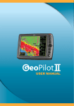
FARM NAVIGATION
User Manual
Corresponding to Software Version
2.5.xx
Dear Customer,
Congratulation for choosing an AvMap Satellite Navigator.
AvMap GPS systems are made in Italy since 1994.
This User Manual is updated to the Software version
2.5.xx released in February 2010 for the AvMap G6
Farmnavigator satellite navigators:
G6 Farmnavigator
G6 Connect Farmnavigator
Your journey, Our Technology
Index
1. Getting started 4
3. Creating and working a field
13
1.1 Content of the box
1.2 Device description
1.3 Mounting 4
4
5
2. Farmnavigator main menu
7
2.1 Fields
2.2 Spray boom
2.3 Farmnavigator settings
2.3.1 Working Width
2.3.2 Spray Boom
2.3.3 Guide lines
2.3.4 Offset
2.3.5 Area Unit
2.3.6 Minimum Speed
2.3.7 General settings
2.4 Camera
2.5 Volume and Brightness
2.6 Bluetooth
8
8
9
9
10
10
10
11
11
11
12
12
12
3.1 Creating a field
3.2 Working a field
3.3 Measuring Perimeter and Area
3.4 Positioning obstacles / soil samples
3.5 Setting the Guide lines
3.5.1 Parallel guide lines
3.5.2 Contour guide lines
3.5.3 Tram lines
3.5.4 Round and Round
3.6 Assisted driving
3.7 Using the spray boom virtual control 13
13
14
15
15
16
17
18
18
18
19
4. Fields Database
22
4.1
4.2
4.3
4.4
22
23
27
27
Editing the fields
Exporting field data to Google Earth
Printing the field map from Google Earth
Importing the field data
Appendix A: The Dop
29
AvMap - 3
1. Getting started
1.1 Content of the box
•
•
•
•
•
•
•
•
1.2 Device description
G6 Farmnavigator / G6 Connect Farmnavigator
Charger 220 V
Car charger 12 V with cigarette lighter plug
Waterproof External GPS receiver
Protective rubber frame
Holder with suction cup
USB cable
External DVBT TV antenna *
Microphone
Serial Port
USB (master/slave)
Audio output
Power supply
(with CA power supply cable)
Power key
*Only G6 Connect Farmnavigator model
Speakers
4 - AvMap
Magnetic
support
Farmnavigator
1.3 Mounting
1. Attach the magnetic support the suction cup holder.
External GPS
antenna connector
Connector for
car charger 12 V
Connector for
magnetic support
Sensor for the
automatic
brightness
control
Reset
SD Slot
ON -OFF
2. Mount the suction cup holder on the windshield of
your farm machine. Please reassure that the windshield
is free from grease and wet the suction cup to improve
the adhesion.
3. Connect the 12V power cable to the connector in the
magnetic mount, and then to the cigarette lighter plug
in your vehicle.
4. Connect the cable of the GPS antenna to the 9 pins
Connector coming out of the magnetic support. 5.
Connect the antenna cable with the screw coupling
to the GPS antenna and mount the antenna above the
steering axle. If the hood of your farm machine is not
made of magnetic material (plastic or aluminium etc.)
AvMap - 5
Farmnavigator
you can mount a metal plate or a washer on your hood
with for example hot glue.
6. Now you can put the Farmnavigator in the magnetic
mount and start working.
ATTENTION:
Never remove the SD Card while the software is running.
Even if the device has been sent to stand by mode,
software is still running in the background. Always quit
the software with the exit button in the road navigation
menu, and wait until the device returned to the start
menu. Otherwise a system error will occur which could
cause heavy data loss.
6 - AvMap
2. Farmnavigator main menu
In order to use the Farmnavigator functions open the
navigation software. Open the main menu and click the
Farmnavigator button in the upper right corner.
In the Farmnavigator menu you can find the following
buttons.
• Fields
• Spray Boom
• Settings
• Import Fields
• Camera
• Volume and brightness
• Bluetooth
In the upper bar you can find the Field View button, that
opens the field view, and the Road Navigation button,
that brings you back to the road navigation main menu.
From the field view you can open the Farmnavigator
menu by clicking the button with the tractor icon in the
bottom left corner of the screen.
AvMap - 7
Farmnavigator
2.1 Fields
In the main menu press the Fields button to enter the
fields’ database, which contains detailed information for
each field. Here you can create a new field or open a
saved field, to continue a previously started work. To go
back to the main menu, press the Back button in the
upper left corner.
2.2 Spray boom
This button opens the setting page for the spray boom
virtual control. You can set here the length of your spray
boom bar, the exact number of segments, the number of
nozzles and the distance between them. The spray boom
virtual control function can be used to control sprayers
but also other machines such as Spreaders and Planters
that work in a similar way. You can find the Spray Boom
button also in the Settings menu.
8 - AvMap
Farmnavigator
2.3 Farmnavigator settings
Use this button to change the Farmnavigator settings. In this
screen you can adjust the functions of the Farmnavigator
to your Farm-machine and to its attachments.
The settings include:
• Working width
• Spray Boom
• Guiding lines
• Offset
• Area unit
• Minimum speed
• General settings
To go back to the main menu, press the Back button in
the upper left corner.
2.3.1 Working Width
Here you can set the working width of your farm machine.
This value is used to calculate the distance between
AvMap - 9
Farmnavigator
the guiding lines. Attention: If the virtual spray boom
commander is activated its settings will be used for the
calculation.
2.3.2 Spray Boom
The Spray Boom button can be also found in the
Farmnavigator main menu (par. 2.2). Read Par. 3.7 on
how to use the spray boom virtual control.
2.3.3 Guide lines
Here you can select from four different types of navigation
(par. 3.5).
2.3.4 Offset
This setting allows you to move the position of your GPS
receiver virtually forward and backwards (to the position
of your sprayer), to have more accuracy in work.
10 - AvMap
Farmnavigator
2.3.5 Area Unit
Here you can select the Unit of Measurement:
Hectare = (km/h, m, cm,)
Acre = (imperial, mph, Foot, Inch)
2.3.6 Minimum Speed
Set here the minimum speed for recording GPS positions.
As the GPS can move a bit around while standing still, a
setting of 0.5 MPH minimum speed is suggested to avoid
recording these oscillations which false the real GPS
position.
2.3.7 General settings
In this menu the basic settings of the device, like
language or display settings can be changed. For more
info about device general settings, please read the full
road navigation manual.
AvMap - 11
Farmnavigator
2.4 Camera
Click this Button to display the pictures from the rear view
camera. On the left you can find two buttons.
Field View: Click this button to switch to the field view screen.
Farmnavigator: Use this button to go back to the farm
navigation main menu.
2.5 Volume and Brightness
You can adjust here the brightness of the display and
the volume of vocal instructions and acoustic signals, by
pressing the left and right arrows. Press Accept to confirm
and to go back to the main menu.
2.6 Bluetooth
The Farmnavigator also offers a hand-free calls function
for Bluetooth phones. Please read the full road navigation
menu to get instructions on how to pair your mobile
phone with the Farmnavigator.
12 - AvMap
3. Creating and working a field
3.1 Creating a field
Open the Farmnavigator Main Menu and click the Field
button. A list of all saved fields appears. At first use the
table is empty. To create a new field press the button
Create New. The field view will be opened.
3.2 Working a field
Before starting a work on a field, or before starting
the measurement of the field, it is important to set
the working width (the width of the machine you are
using),
1. Go back to the Farmnavigator main menu
2. Press the Farmnavigator Settings button
3. Press the Working Width button
4. Use the left and right arrows to set the desired width
5. Press Accept to confirm
Please read par. 2.3 for the other settings.
AvMap - 13
Farmnavigator
Press Field view. Press the Start Work button in the
bottom bar to start recording the data (worked area,
speed, perimeter and area) that will be saved in the
Fields Database.
To stop the recording of the worked area click stop in the
down left corner. You can start working on this field again
at any time with a click on start or when you reopen the
field in the fields’ database.
3.3 Measuring Perimeter and Area
The first operation you can do is to measure the field
by driving along the perimeter of the field. Drive some
meters at first. Then click the measure button (with
the ruler icon). The boundary now is recorded from the
starting point (red arrow). Now drive around the field
until you have reached the starting point, and then click
the measure button again. The Field limits are now saved
and the area is calculated. This information is stored in
14 - AvMap
Farmnavigator
the fields’ database.
3.4 Positioning obstacles / soil samples
You can record the positions of soil samples or obstacles,
like trees or holes.
To save a position, go as near as you can to the relevant
object and click the obstacle button (with the orange
cone icon). The positions of obstacles and soil samples
are now saved in the fields’ database and are shown on
the map with an orange cone icon and a progressive
number.
3.5 Setting the Guide lines
Once you have created the field, you can go on with your
work using the Assisted-Driving function (a.k.a parallel
guidance).
The recording of field perimeter and the reference line
can be done in one step.
AvMap - 15
Farmnavigator
In order to get driving assistance, you need to set the
guide lines.
1. Open the farm navigation main menu
2. Press the Settings button
3. Press Guide lines.
4. Choose among 4 different types of guide lines pressing
the desired option:
• Parallel
• Contour
• Tram lines
• Round and Round
5. Confirm by pressing the Accept button
6. Press Field view in the upper right corner
3.5.1 Parallel guide lines
Parallel guide lines are ideal for fields with straight
boundaries. When driving the first reference line, set
the point A at the beginning of the track by pressing the
16 - AvMap
Farmnavigator
A button. The starting point is shown on the map as an
orange square with an ‘A’ on it. Once the point A is set,
the B button will appear. When you reach the headlands
set the point B by pressing the B button. The point B is
displayed on the Map just like Point A. These two points
are used to draw the reference straight line and the
corresponding parallel lines at a distance previously set
as working width.
3.5.2 Contour guide lines
Contour guide lines are used for fields with curved
boundaries. Drive the first reference line setting the
point A, and then, just before you reach the headlands,
setting the point B. The Farmnavigator will record
each position and draw the exact driven line and the
corresponding parallel lines at the distance previously
set as working width or virtual spray boom width.
3.5.3 Tram lines
AvMap - 17
Farmnavigator
This Option is used to work in fields where tram lines
already have been made (e.g. vineyards). In this mode
Farmnavigator does not guide you but it shows the worked
area and allows using the spray boom virtual control.
3.5.4 Round and Round
Setting the round and round guiding lines you can create
concentric lines starting from the field’s perimeter
up to the centre. Press A, then start driving along the
perimeter and press B when you have completed it: the
software will draw concentric lines up to the centre of
the field.
3.6 Assisted driving
After the Guiding lines have been set, the navigation aid
is displayed above the Map. The navigation aid shows
with two directional arrows in which direction the
steering has to be corrected to drive on the calculated
18 - AvMap
Farmnavigator
guiding line. The deviation from vehicle position to
guiding line is shown between the directional arrows in
m and cm to allow very accurate corrections. On the
left side there are four boxes showing: worked area, trip
(distance covered), speed and DOP (precision of GPS).
For info about the DOP, read appendix A. Once the
work is done, press the Stop Work button. The worked
area (highlighted in green) is saved in the field page in
the Fields Database. You can then open the field and
continue the work.
3.7 Using the spray boom virtual control
Farmnavigator includes a virtual control of the spray
booms. This function can be used to control sprayers
but also other machines such as spreaders and planters
that work in a similar way. When spreading chemicals
on a field it is very important to control the treated
area and to avoid treating twice the same portion of
AvMap - 19
Farmnavigator
terrain. Farmnavigator software will draw your sprayer,
reproducing the exact number of sections and nozzles,
and it will support you to switch the different sections
on and off.
To activate this function press the Spray Boom button in
the main menu and then press the Boom On button.
ATTENTION when the spray boom virtual control is
activated, its settings are used to calculate the working
width, ignoring the width set in the Working Width page
(par. 2.3.1).
Now you can set the number of sections and the width of
each Nozzle using the arrow Buttons.
The Sections are displayed by numbered squares. You can
select each section and change its width by clicking the
modify size button. Use the arrows to adjust the number
of booms and confirm with OK to save the settings and
20 - AvMap
Farmnavigator
continue with the next section.
These settings are saved even if the spray boom virtual
control is deactivated. If the spray boom virtual control
has been set and activated the different sections are
displayed as numbered “LED” lights in the Field View.
Each “LED” shows whether the specific section should be
turned on or off by the operator. Yellow means that the
spray boom can be open, red means that the section is
overlapping an area that has already been treated so the
operator should turn it off.
To open the field database, go to the Farmnavigator
AvMap - 21
4. Fields Database
menu and click the button Fields. A table with every
saved field appears. Select from the table the relevant
field and click open, then press Show Info to see the
full Info. The full Info informs you about the shape of
your field, the work time, the area, the worked area,
the maximum speed and the maximum DOP Value. Click
Select to switch to the next submenu.
4.1 Editing the fields
To edit the data saved with the field, open the Field full
info page and press the Options button.
The options menu includes the following buttons:
Open: You can open previously worked fields and continue
to work.
Edit Name: After a field has been created, it is named
automatically with the data of creation. This option
allows you to rename the field to your wishes.
Clear Obstacles: If you recorded obstacles or soil samples
22 - AvMap
Farmnavigator
in your field, you can remove them with this option.
Clear Worked Area: If you want to start a new work
on a previously worked field, you can clear the worked
area. Perimeter, total area and obstacles positions will
be kept.
Delete: The whole field is deleted.
Export: Open the field then press this button to create a
.kmz file, which can be opened in Google earth. The file
is stored in the SD in the Fields folder.
4.2 Exporting field data to Google Earth
You can export each field created and worked with the
G6 Farmnavigator and view it on Google Earth.
1. Open the Field Database, select the field you want to
export and open it pressing Open Selected. WARNING: in
order to be able to export a field, this has to be open.
2. Go back to the field database, select the field and
press Show Info, press Options and then press Export.
AvMap - 23
Farmnavigator
(If the field has not been opened then the export button
is deactivated). G6 Farmnavigator will convert the field
info in *.Kmz, format, that is compatible with Google
Earth. These files will be saved in the Farmnavigator’s SD
memory, inside the Fields folder.
3. Connect G6 Farmnavigator to the PC with the USB
cable provided, without feeding it, the USB image will
appear on the navigator’s display. The PC will read G6
Farmnavigator as an external memory support and the
“removable disc” window will automatically pop up.
4. In the removable disc window, open the Fields folder:
it contains a folder for each saved field and the *.Kmz
files. Copy the *.Kmz file and paste it in a folder that you
have created for this purpose in your PC.
5. If Google Earth is installed in your PC, you just have
to click on the *.Kmz file to open it. (Download Google
24 - AvMap
Farmnavigator
Earth for free from http://earth.google.com/). It will be possible to see on the Google Earth map the field’s
perimeter marked with a coloured line, and the obstacles saved on the field.
The Places window shows all the data relative to the field (area and obstacles positions). Click on the Fields
AvMap - 25
Farmnavigator
name or on the Info icon to view more data about the work on the field (duration of the work, maximum DOP,
working width settings, etc ).
4.3 Printing the field map from Google Earth
26 - AvMap
Farmnavigator
You can print out the map of your fields with all the
relative info.
1. Click on the name of the field in the place window.
2. Click on the File menu, then click on Print.
3. The Print dialogue window will open. Select the
second and click on the Print button.
Google Earth will print the map of the field and its
data.
4.4 Importing the field data
You can transfer the field database form one G6
Farmnavigator to another, exporting the data and then
importing them in the new Farmnavigator.
1. To export the files, follow the procedure described in
par. 4.2, up to step 4.
2. To import the file please connect the G6 Farmnavigator
in which you want to import the data to the PC with the
USB cable provided. Do not feed the navigator. The USB
AvMap - 27
Farmnavigator
image will appear on the navigator’s display. The PC will
read G6 Farmnavigator a san external memory support
and the “removable disc” window will automatically pop
up.
3. Copy and Paste inside the Fields / Import folder of G6
Farmnavigator (removable disc) the *.Kmz files previously
copied on the PC
4. When the procedure is over, close the window and
remove safely the hardware.
5. Switch on the Farmnavigator and open the main menu.
Press Import Fields to see the list of *.Kmz files, select
the file and press the Import button on the right to add
the field in the database.
6. Go back to the main menu and press Field: in the
imported field is now added to the list.
The DOP (Dilution of precision) is a value indicating the
28 - AvMap
Appendix A: The Dop
precision of the GPS
The Errors in the position a GPS receiver gives you are due mainly to two factors: the precision with which
the distance to each GPS satellite is known, and the geometry of the satellites. Distance errors can be
compensated for by using WAAS, and other techniques: Farmnavigator is equipped with a special waterproof
external GPS antenna with a U-Blox receiver that is WAAS/EGNOS DGPS enabled. But the maximum position
accuracy you can achieve is limited by GPS satellite geometry, that varies during the day.
The signal from each GPS satellite has level of precision; depending on the relative geometry of the satellites,
these precisions can be combined to give amplified or greatly compressed precision. A low DOP value represents
a better GPS positional precision due to the wider angular separation between the satellites used to calculate
a GPS unit’s position. The higher the DOP, the greater the possible error in the accuracy of your position.
Other factors that can increase the effective DOP are obstructions such as nearby mountains or buildings.
It is important to know the DOP value in every moment as this information helps you to understand how much
you can trust the precision of the GPS in that moment. If the DOP is bad then you could consider to wait until
the DOP gets better to start the work.
AvMap - 29
Farmnavigator
DOP Value Rating Description
1
1.1 - 1.2
1.3 - 2
Ideal This is the highest possible confidence level.
Excellent At this confidence level, positional measurements are considered accurate enough to
meet all but the most sensitive applications.
Good
The Farmnavigator is only working if DOP is better 2.0. If DOP is above 2.0 Farmnavigator will stop do to on
to bad Sat constellation
SATCONSYSTEM
Bundesstr. 7
97531 Obertheres
Germany
Tel.: +49 (0) 9521/7072
Fax: +49 (0) 9521/1350
[email protected]
30 - AvMap
AvMap USA
www.farmnavigator.com
133 Falmouth Road
Mashpee
MA 02649
[email protected]
www.farmnavigator.com