1
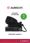
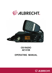
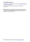
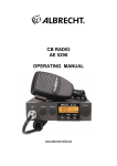
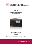
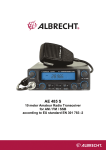
USER MANUAL
AE7500
AM/FM/SSB CB-Transceiver
English
Downloaded from www.cbradio.nl
English
19
1
Table of Contents
2
3
4
Introduction ...................................................................................................... 20
Safety Precautions ........................................................................................... 21
Installation ........................................................................................................ 21
4.1
Contents ................................................................................................... 21
4.2
Mounting the AE7500 ................................................................................ 21
4.3
Power Connection ..................................................................................... 21
4.4
Antenna Connection .................................................................................. 22
4.5
SWR Adjustment of the Antenna ............................................................... 22
4.6
Country Code Setting ................................................................................ 22
5 Location of Controls ......................................................................................... 23
6 LC Display and Indicators ................................................................................ 25
7 Basic Operation................................................................................................ 26
7.1
Power on ................................................................................................... 26
7.2
Volume ...................................................................................................... 26
7.3
Squelch ..................................................................................................... 26
7.4
ASQ .......................................................................................................... 26
7.5
Channel selection...................................................................................... 26
7.6
Select Operation Mode.............................................................................. 26
7.7
Monitoring the active Channel ................................................................... 28
7.8
Channel Memories .................................................................................... 28
7.9
Channel 9/19 direct access ....................................................................... 28
7.10 Last Channel Recall .................................................................................. 28
7.11 Dual Watch Monitoring .............................................................................. 28
7.12 Scan mode ................................................................................................ 29
7.13 Transmitting .............................................................................................. 29
8 Advanced Operation......................................................................................... 29
8.1
Step Key ................................................................................................... 29
8.2
Clarifier ..................................................................................................... 30
8.3
Tone Control ............................................................................................. 30
8.4
Microphone Gain Adjustment .................................................................... 30
8.5
Receiver Gain Adjustment ......................................................................... 30
8.6
Transmitter Power Adjustment .................................................................. 30
8.7
Noise Blanker............................................................................................ 30
8.8
Menu Functions (additional settings) ......................................................... 30
8.9
Echo Function ........................................................................................... 31
8.10 All Mode Talkback ..................................................................................... 31
9 Warranty Information ........................................................................................ 31
10
Disposal and Recycling ................................................................................ 31
11
Technical Details ........................................................................................... 32
12
Declaration of Conformity / Konformitätserklärung ....................................... 33
13
Albrecht Radio Passport ............................................................................... 34
2
Introduction
This AM FM SSB transceiver AE 7500 is a universal CB radio for 12V DC power
supply. It can be connected in vehicles, at high-performance 12V batteries, such as
rechargeable lead batteries, and via a suitable 12V power adaptor with at least 6A
stabilized continuous current, at 230V mains power supply. The radio is, due to its
operating mode, which demands careful operation and repeated adjustment during
operation, not everywhere permitted to be used in vehicles while driving. Find out
about the country’s regulations, if you are permitted to operate radios in the
20
English
respective country while driving. In Germany the well-known “mobile phone
prohibition” applies only for mobile phones and not for two-way radios.
The radio is intended for intermitting operation with an average transmission time of
approx. 10% of the On-time, as usual for CB radios. This device is not intended for
continuous transmission without regular receiving periods to cool down. Avoid high
humidity, extreme high and low temperatures, dust and direct sunlight. Open your
radio only if you have the necessary expertise, the correct tools and necessary
measurement instruments.
On delivery the device has (according to the country of sale) the internationally usual
CB radio range with 40 channels in all operating modes AM, FM, USB and LSB
switchable. The Declaration of Conformity according to the new European standard
EN 300 433-2 applies only, if the device is not modified and used according to this
user manual. Any expansion of the frequency range to amateur radio and the use of
other channels and operating modes than permitted in the respective country is only
permitted for licensed amateur radio operators and can have legal consequences for
unauthorized persons.
Legal information
The revised automotive directive / EMC directive 2004/104/EG (14. 10.2004) again
allows to use non-safety-relevant CE marked after-market equipment like CB
transceivers in car installations. Because of EMC reasons, the car manufacturers
have the right to issue installation rules and instructions for installing transmitters and
their antennas in cars. These rules and instructions are valid for amateur radio
installations as well as for any other transmitting device in cars.
3
Safety Precautions
For vehicle installation mount the radio with the supplied screws and the mounting
bracket in a suitable location in your vehicle. Ensure that the installation location
cannot cause the risk of injuries for driver or passengers and avoid the immediate
vicinity of heater or A/C outlets.
4
Installation
4.1
Contents
Unpack and inspect your AE7500 for missing or damaged components. Your
AE7500 includes the following items:
•
•
•
•
•
4.2
AE7500 Transceiver
Up / Down Microphone
Mounting Bracket and Installation Hardware
Power Cord
Operating Manual
Mounting the AE7500
Choose a location with easy access to all front panel controls and air circulation
available to the rear panel and aluminium heatsink. Do not install the transceiver in
any compartment that restricts airflow. Attach the mounting bracket to the vehicle first
then mount the transceiver to the bracket. If the rear panel is not easily accessible
you may want to attach the power cord and antenna feed line prior to mounting.
4.3
Power Connection
Connect your radio with the supplied DC cable to the 12 V vehicle power, or a 12V
power adapter. The permitted voltage range reaches from 11 Volts to 15.6 Volts at
maximum. The battery or the power adapter must be able to supply at least 6-8A
stabilized. The power cord should not be extended. In vehicles always try to connect
directly to the battery terminals. This gives you the best protection against
English
21
interferences from ignition and alternator as well as the most stable operating
voltage.
In case the in-line fuse in the DC cable blows, check the possible cause first (mostly
reverse polarity and a protective diode has kicked in) and replace the fuse only with
the same type (10A, American glass fuse).
Connect the red cable to the + terminal and the black cable to the – terminal of
the power source.
4.4
Antenna Connection
The transceiver will operate using any standard 50-ohm ground-plane, vertical,
mobile whip, long wire or similar antenna. The antenna should be rated at 50 watts
PEP minimum. A standard SO-239 type connector is provided on the rear panel of
the transceiver. Connection is made using a PL-259 and high grade coaxial cable
(RG213 or RG58A/U is recommended). A ground-plane antenna provides greater
coverage and is recommended for fixed station-to-mobile operation. For point-topoint base station operation, a directional beam antenna operates at greater
distances even under adverse conditions. A non-directional antenna should be used
in a mobile installation; a vertical whip is best suited for this purpose. The base
loaded whip antenna normally provides effective communications.
For greater range and more reliable operation, a full quarter wave whip may be used.
Either of these antennas use the metal vehicle body as a ground plane.
4.5
SWR Adjustment of the Antenna
After you have determined that the installation is correct and the radio is operational,
it is important to determine the antenna system’s SWR (Standing Wave Ratio). Prior
to taking any measurements make
sure the SWR bridge (meter) is in good working condition and is calibrated. To
ensure your radio is performing properly the SWR should never exceed 1.5 to 1. This
is critical due to the high level of gain developed in the RF deck. Never transmit on
any antenna system where the SWR exceeds 1.8 to 1. This will stress the output
stage and could destroy the RF transistors; this type of misuse and failure is not
covered under warranty.
4.6
Country Code Setting
Every time the AE7500 is switched on, ‘HELLO’ is displayed, then the country code is
shown, for a few seconds..
Description of all country codes
d4
E
PL
U
U5
22
Germany 80 channels FM 4 Watts, 40 channels AM 4 Watt, 40
channels SSB 12 Watts, also for CZ and SK
Europe according to new CEPT regulation with 40 channels FM 4
Watts, 40 channels AM 4 Watts und 40 channels SSB (12 Watts)
Poland with 40 channels FM 4 Watts, AM 4 Watts and SSB 12 Watts
with Offset = 0 kHz
UK with 40 UK channels and 40 international channels, FM, 4 Watts,
no AM, no SSB
USA, as E, setting for countries not using FM, but only AM and SSB.
Can also be used in Europe (in countries, where E is allowed)
English
Changing the Country Code
•
•
•
•
Turn the device off.
Turn the device on again while pressing the MEMORY key. The programmed
country code is displayed.
Select the desired country code with the channel selector.
Turn the device off and on again.
The device now works with the new country code.
5
Location of Controls
Reference Front Panel Diagram
15
13
14
2
1
17
20
16
19
4
3
18
6
21
22
8
5
7
10
9
12
11
(1) Power ON/OFF and Volume Control
(2) Squelch Control
(3) Microphone Gain Control (recommended setting: full clockwise)
(4) RF Gain Control (recommended setting: full clockwise)
(5) ASQ ON/OFF, PA (recommended setting: ASQ ON)
(6) RF Output Power Control (recommended setting: full clockwise)
(7) Tone Control (recommended setting: center)
(8) Echo Volume Control (recommended setting: full counter clockwise)
(9) Echo Delay Control (recommended setting: center)
(10) CLARIFIER (recommended setting: center)
(11) All Mode Talk Back Control (recommended setting: full counter clockwise)
English
23
(12) CHAN (channel selector)
(13) METER
The lower scale indicates the received signal strength in S-units, while the upper
scale indicates the RF output power in Watts during transmitting.
(14) CH 9/19 Direct Access
(15) FUNCTION
This key is used to operate the functions that are printed below the control keys.
Press and release, FUNC will be displayed on the LCD indicating that the function
command is activated. After a second key is pressed or if no other key is pressed
within 3 seconds the FUNC will disappear from the screen.
(16) SCAN, second function MENU
(17) MEMORY LOAD, second function MEMORY
(18) MONI
(19) STEP, second function NB
(20) LAST CHANNEL RECALL, second function ECHO
(21) MODE (AM, FM, USB, or LSB), second function DW
(22) DISPLAY
MICROPHONE INPUT SOCKET (not shown)
6-pin, lock ring type, microphone connector located on side chassis of transceiver.
Microphone wiring is as follows:
Pin 1 : Microphone Audio
Pin 2 : Receive
Pin 3 : Transmit
Pin 4 : Down (Up w/ 22K Ohm Resistor)
Pin 5 : Ground
Pin 6 : +13.8 VDC
The following sockets are located on the back panel of the radio
EXTERNAL SPEAKER SOCKET (not shown)
External speaker socket, marked EXP SP. For use with 4 to 8 ohm external speaker.
PA Speaker Socket (not shown)
PA speaker socket, marked PA. By connecting an external loudspeaker with this
socket, the A7500 can be used as an audio amplifier. For connection a 3.5mm Mono
plug is needed.
The following controls are found on the microphone
PUSH-TO-TALK (PTT) key
Located at the side of the microphone
24
English
UP and DOWN keys
Located on the front of the microphone. Remote control of CHAN control. Press the
up arrow to increase the channel number and press the down arrow to decrease the
channel.
6
LC Display and Indicators
The LCD screen is the status display for the majority of the transceiver’s functions.
1
2
3
4
5
6
7
8
9
10
11
12 13
14
15
16
(1) FUNCTION
Indicates the function button has been activated and that the function dependent
controls may be accessed.
(2) SCAN
Indicates that the transceiver is in scan mode..
(3) TX
Indicates that the transmitter is on.
(4) USB \ LSB \ FM \ AM
Indicates the selected operating mode.
(5) NB and ANL
Indicates that both the noise blanker and the automatic noise limiter are active.
(6) SHIFT
(only available in amateur radio version)
(7) RPT
(only available in amateur radio version)
(8) DW
Dual Watch enabled
(9) RGB
Roger Beep enabled
(10) ECHO
Echo Function enabled
(11) Key Tones
Key Tones enabled
English
25
(12) Busy
Indicates that the Squelch is open
(13) ME
Indicates that MLOAD or MSAVE was pressed
(14) 5 DIGIT FREQUENCY DISPLAY
Indicates transmit and receive operating frequencies
(15) CHANNEL NUMBER
(16) PEAK READING RF POWER METER
Indicates relative peak RF output power. Only active when using SSB
7
7.1
Basic Operation
Power on
The On/Off switch is combined with the volume control. To switch on, turn that
control slightly clockwise until it has clicked. To switch off, turn the volume control full
counter clockwise until it has clicked again.
7.2
Volume
Set the volume to your convenience by the VOL control. If the receiver is muted, set
this control to medium and adjust the volume when you receive a signal.
7.3
Squelch
Set the squelch, so that the noise is just not audible. In this position the squelch
opens even for weak signals and is in the most sensitive position. When opening the
squelch beyond this point to the right (clockwise), the signals must be stronger to
come through.
To check for very weak stations the receiver muting can be temporarily disabled by
pressing the MON key. This function is independent from the squelch control and
activated ASQ function.
7.4
ASQ
This automatic squelch function does not need any adjustment and works fully
automatic at maximum sensitivity. It opens at any signal which is good enough to be
understood. Turn the ASQ/PA selector into position ‘ASQ’. However, the ASQ
function is limited to normal receiving conditions on the CB band. In case of nuisance
by overreaching far distant stations or if you like to suppress weaker stations, it may
be better to use the standard squelch instead of the ASQ. To disable this function
turn the ASQ/PA selector into position ‘Normal’.
7.5
Channel selection
Rotate this knob to select the operating channel. Alternatively the channel can be
selected by the up and down keys on the microphone.
7.6
Select Operation Mode
Press the MODE key to cycle around AM, FM, USB and LSB modes. The selected
mode is shown on the display. They mean:
AM
FM
USB
26
Amplitude modulation A3 with full carrier
Narrowband frequency modulation (max. 2.0 kHz range)
Single side band modulation, upper side band (Upper Side Band)
English
The different modes for CB radios have historical reasons, as CB radio is already,
since the 1950s in existence. AM mode (amplitude modulation) corresponds with
the technical process of medium and short wave radio and is today, except for CB
radio, only used for aircraft radio. When speaking the transmission power is varied in
the rhythm of the voice. AM is traditionally the radio mode which is used by truck
drivers worldwide on CB radio. The low residual noise is advantageous if for instance
in diesel trucks with little interference the squelch stays open. The receiving
characteristics in AM corresponds rather with the human ear: distant stations seem
lower than stations nearby; still you can perceive if other persons are speaking on
your channel, even if a local station seems to blanket everything: at least the
blanketing tone can be heard and you can check back at later stage! One of the
disadvantages of AM is shorter range compared to FM and SSB and the higher
sensibility of AM for ignition interference and board computers.
In FM the transmission the power is constant, even when speaking, hence hardly any
interferences of other devices are to be expected in this mode. Instead, when
speaking the frequency of the radio varies, hence it is called frequency modulation.
Due to expected interferences in AM and SSB modes some countries for a long time
permitted only FM. Advantage is the greater range compared to AM and the same
volume of nearby and distant stations as well as a clear modulation sound. Loud
noise, which can be heard with weak or missing signals, is a disadvantage. In F M
mode it is virtually impossible to leave the squelch open.
SSB (Single Sideband Modulation) marks the highlight in the development of longdistance voice transmission. The transmission mode SSB avoids the disadvantage of
the low range of AM and focuses the entire transmission power on a minimum
frequency width, where during a speech pause the power is nearly shut down to
zero. During receiving a special circuit makes sure that the “side bands” and the
“carrier”, which were cut off during transmission, are restored. This allows an
enormous improvement in range compared to AM and FM. Not only the transmitter
has a greater range, but also the receiver has, due to the halved bandwidth, better
sensitivity. The price for this is the disadvantage that for receiving very accurate
tuning is necessary, and that during transmission interferences of neighboring
devices is greater. Due to the necessary fine tuning of the receiver with the Clarifier,
the use of SSB while driving a vehicle is a problem and can – such as making a
phone call – distract from the traffic. SSB is rather an operating mode for base
station. This is the reason why SSB today is only used by skilled radio operators –
you virtually have to train and develop some intuition for the correct setting.
USB and LSB
In SSB mode a conventional channel is separated in two halves: the so called upper
side band (Upper Side Band) and the lower side band (Lower Side Band). Both can
be used independently. Example: you transmit on channel 9. In reality you only use
the frequencies from 27.065 up to approx. 27.070 MHz, while in LSB you are using
the frequencies below 27.065 to approx. 27.000 MHz. Both side bands are mirrored;
hence transmitter and receiver must be set to the same side band.
How to Receive SSB
As the receiver station you cannot know, which side band your counter station is
transmitting. The fact that the counter station is transmitting SSB is easily detected,
since the “squawking sound” is very different from FM or AM signals. Receive first in
USB. Very carefully turn the Clarifier. If you can hear a “Mickey Mouse” voice, try to
fine tune to a recognizable pitch. If this does not work, then try the other side band
LSB. You need some routine until you can clearly hear your dialog partner in SSB
mode.
English
27
7.7
Monitoring the active Channel
The squelch and the ASQ function can be temporarily disabled by the MONI key.
As long as this key is pressed, you can listen into that channel. Be careful if using
FM, because of its loud background noise.
7.8
Channel Memories
Frequently used channels and their respective mode can be stored and retrieved via
the MSAVE/MLOAD key with the in 4 memories. The settings are saved in flash
memories, thus all contents are kept, even if the radio is disconnected from the DC
supply.
Store Channel into Station Memories (1-4)
• Tune to the desired channel. Press FUNK + MSAVE +Station Memory (1-4)
• ME for “Memory” is shown on the display
If the ME indicator disappears before you press the memory channel button, the
information will not be saved and the process must be repeated.
Recall Channel from Memory
• Press MLOAD and the Station Memory (1-4) to retrieve the station memory
(after entering MLOAD the display shows ME).
7.9
Channel 9/19 direct access
The most frequently used channel 9 (call channel and trucker channel in Germany)
and channel 19 (second trucker channel and AM call channel in many other
countries) can be easily selected by briefly pressing this key.
• Press once to select channel 9
• Press again for 19
• Press once more to return to the previously used channel
Channel numbers for 9 and 19 are flashing to confirm the selection of a direct
channel.
7.10 Last Channel Recall
Press the LCR key to return to the last frequency that was transmitted on for more
than 3 seconds.
7.11 Dual Watch Monitoring
To regularly monitor two different channels use Dual Watch DW
• Select the first channel e.g. channel 26.
• Press FUNC and then DW, the display shows “DW” .
• Now select the other channel, e.g. channel 18.
Your radio will now constantly switch from channel 18 to 26, check there briefly for a
signal and switch back to 18. If channel 26 is busy your device stays in receiving
mode and only afterwards switches back to 18.
Turn off dual watch
• Briefly press the PTT key or press the DW key once again.
28
English
7.12 Scan mode
Your AE 7500 has an automatic channel scan, which can be used to observe all
channels consecutively.
First choose the mode (AM or FM). Adjust the squelch control to the point at which
the receiver should open or activate the ASQ.
Start channel scan
•
Briefly press the SCAN key
•
Scan starts almost immediately by scanning all the channels upwards and the
SCAN icon will appear on the LCD.
•
Scanning is stopped at each signal worth receiving and you can listen into the
conversation.
Without any action the scanning will resume after the communication on the channels
has stopped.
Stop channel scan
•
You can stop the scan at any time by pressing the SCAN key a second time.
•
Pressing the transmission button will also automatically stop the scan modus.
7.13 Transmitting
Before transmitting, you should check, that no other station is transmitting. This is
done best by pressing the MONI key. With the PTT key (Push To Talk) on the side
of the microphone you can switch between receiving and transmitting:
• Press PTT key to transmit.
The TX icon is shown on the LCD during transmission
• Release PTT key again to switch back to receiving.
When transmitting, you can speak from a distance of about 5-10 cm into the
microphone. The modulation amplifier of your AE 7500 is sensitive enough and
enables you in most cases to speak with even more distance, depending on how
loud your voice is. An automatic regulator ensures that your partner always hears
your signal at the same volume. After pressing the PTT button, please wait about ½
second before you start speaking. Please remember - that different from GSM
phones - you share one channel common for transmit and receive, and your
transmitter and the receiver(s) on the distant side need a certain time to switch on.
8
8.1
Advanced Operation
Step Key
The channel spacing in the CB range corresponds with the usual standard of the
international 10 kHz spacing, where some channel are spaced 20 kHz instead of
10kHz. You can change the frequencies with the CHAN control on the readio or with
the UP/DOWN keys on the microphone by 1 channel. With the STEP key you can
change the displayed frequency also in steps of 500 Hz to for finer tuning.
Example: channel1, 26.965 MHz
• Press the STEP key
• Now you can tune with the CHAN control between 26.9600 and 26.9695
MHz.
• You also have the CLARIFIER for further fine tuning.
According to the regulations for CB radio the transmission frequency is unchanged.
NOTE: When stepping in 1 kHz increments, you are limited to tune within a 10 kHz
frequency range.
English
29
8.2
Clarifier
The CLAR control allows the fine tuning of the receiver frequency from 1kHz below
to 1kHz over the indicated frequency. The clarifier is primarily used to adjust the tone
and readability of an incoming SSB signal. For normal operation turn this knob to
the center position. The transmitter frequency is not affected by this control.
8.3
Tone Control
Turn the TONE control to adjust the receiver sound to your convenience. The
transmitter sound is not affected.
8.4
Microphone Gain Adjustment
Controls the sensitivity of the microphone amplifier circuit. The gain increases as the
control is rotated clockwise. For optimum setting, press the push-to-talk switch on the
microphone and speak in a constant tone into the microphone. While speaking,
rotate the MIC-G control clock-wise until the modulation LCD display reads +30.
Next, rotate the control counter clockwise until the +30 segment of the display starts
to flicker.
8.5
Receiver Gain Adjustment
Adjusts the receiver sensitivity to both signals and background noise. This effects the
distance at which a signal can be detected. Turning the RF-G control counterclockwise reduces the receiver sensitivity. This is particularly useful in areas where
large volumes of signals are present.
8.6
Transmitter Power Adjustment
Continuously variable control for adjusting the RF output power of the transmitter in
all modes. To reduce the RF output power rotate the PWR control counter
clockwise. To increase rotate the control clockwise.
8.7
Noise Blanker
This circuit eliminates pulse type interference usually associated with automotive
ignition systems. The noise blanker is activated or deactivated by successively
pressing the FUNC and the NB key. If enabled, the NB icon is shown on the LCD.
8.8
Menu Functions (additional settings)
Key Tones on/off
• Press the SCAN/MENU key for more than 3 seconds.
The LCD will show “bP” followed by “on” or “off”.
• Turn the CHAN control to toggle between on and off. If the Key Tones are
enabled a note icon is shown on the LCD.
Roger Beep on/off
When activated a short 1 kHz tone will automatically be transmitted upon release of
PTT switch. This notifies contacts that your transmission has ended and you are
ready to receive their signal.
• Press the SCAN/MENU key for more than 3 seconds and again one time
briefly. The LCD will show “r9b” followed by “on” or “off”.
• Turn the CHAN control to toggle between on and off. If the Roger Beep is
enabled, the RGB symbol is shown on the LCD.
Illumination colour
• Press the SCAN/MENU key for more than 3 seconds and again two times
briefly. The LCD will show “LI9Ht” followed by a number representing the
colour.
• Rotate the CHA control to select the colour. Zero represents no illumination.
30
English
Transmission Time Limiter
The maximum permitted uninterrupted transmission time can be limited. After the
selected time is expired the transmitter turns off. The PTT button must then be
released to reset the time-out timer and the radio is able to transmit again.
• Press the SCAN/MENU key for more than 3 seconds and again three times
briefly. The LCD will show “tot” followed by the time in minutes, or “of”
representing timer off.
• Rotate the CHAN control to select the tot time in steps of 5 or off.
An inactivity of more than 3 seconds exits all menu settings.
8.9
Echo Function
The Echo Function of the AE7500 comprises of four controls.
It is enabled or disabled by successively pressing the FUNC and the NB key. If
enabled, the ‘Echo’ icon is shown on the LCD. The intensity of the echo is controlled
by the E-VOL Control. With the E- DEL Control the time between the echo
repetitions is adjusted.
To achieve an echo effect, the echo delay should be longer and the echo volume
less then maximum. To get a reverb effect, the delay time must be low to get a high
density of repetitions and the echo volume must be set near to the maximum.
Avoid to adjust the echo volume to high, because this could lead to an unreadable
signal. The sound of your transmission can be monitored with the AMT function,
which is described next.
8.10 All Mode Talkback
The ATM function allows the operator to monitor the transmitted audio of the AE7500
in all modes. Turn this ATM control to adjust its volume to your convenience. In case
of audio feedback, the ATM volume or the microphone gain must be reduced. To
disable the talk back, turn this control full counter clockwise.
9
Warranty Information
The manufacturer/retailer guarantees this product for two years from date of
purchase. This warranty includes all malfunctions caused by defective components or
incorrect functions within the warranty period excluding wear and tear, such as
exhausted batteries, scratches on the display, defective casing, broken antenna and
defects due to external effects such as corrosion, over voltage through improper
external power supply or the use of unsuitable accessories. Defects due to
unintended use are also excluded from the warranty.
Please contact your local dealer for warranty claims. The dealer will repair or
exchange the product or forward it to an authorized service center.
You can also contact our service partner directly. Please include your proof of
purchase with the product and describe the malfunction as clearly as possible.
10
Disposal and Recycling
This radio was manufactured low-emission according to the European
WEEE directive. Please note that electronic and electric devices are not to
be disposed of with the household waste; return these devices to collection
points. Returning devices is free of charge for end users, since the industry
is covering the disposal costs. By returning the device to a collection point
you contribute to the recycling of valuable raw materials.
The crossed-trash bin symbol on the type label is intended as a reminder!
English
31
11
Technical Details
TRANSMITTER
Frequency Range:
Modulation Modes
Carrier Suppression:
Unwanted Sideband Suppression:
kHz tone)
Spurious Radiation:
Frequency Accuracy:
Maximum FM Deviation:
Output Impedance:
Microphone Impedance:
Power Consumption:
Power Output:
26.565 – 27.9912 MHz
AM, FM, SSB
Better than 40 dB below peak output
Better than 50 dB below peak output (1
Better than 50 dB below peak output
Better than +10 ppm from 0 – 40° C after
15 minute warm up
2 kHz
50 ohms
600 ohms
6 amps maximum
FM:
4 Watts (Max.)
AM: 4 Watts Average (Max.)
SSB: 12 Watts PEP (Max.)
RECEIVER
Frequency Range:
Tuning Steps:
Clarifier Range:
Sensitivity:
Intermediate Frequencies:
Image Rejection:
IF Rejection:
Selectivity:
Noise Blanker:
Dynamic Range:
Audio Output Power:
Audio Output Impedance:
Power Consumption:
Dimensions:
26.565 – 27.9912 MHz
10 kHz, 500 Hz
+/-1.0 kHz
SSB and AM 0.25uV for 10 dB S+N/N
FM better than 0.3uV for 12 dB SINAD
Minimum discernable signal -135 dBm
1st IF: 10.695 MHz, 2nd IF: 455 kHz
SSB IF: 10.695 MHz
Better than 70 dB
Better than 80 dB for all frequencies
-6 dB -60 dB
SSB: 4.2 kHz 8.5 kHz
AM, FM: 6.0 kHz 18 kHz
All mode, seven stage high gain type
Better than 100 dB
2 watts minimum (into 8 ohms, with less
than 7% THD)
8 - 16 ohms
500 milliamps
7.75(L) x 10.75(W) x 2.5(H) Inches
Service Address and Technical Hotline (for units sold in Germany)
PST professional support technologies GmbH
Breitscheider Weg 117a
D - 40885 Ratingen
Contact our service hotline by phone 01805-012204 (14 cent/minute from German
fixed network) or e-mail at [email protected] .
© 2013 Alan Electronics GmbH
32
English
12
Declaration of Conformity / Konformitätserklärung
We hereby declare that our product: / Wir erklären hiermit, dass unser Produkt
CB
CB-Radio
Albrecht AE 7500
satisfies all technical regulations applicable to the product within the scope of EU Council
Directives, European Standards and national frequency applications:/ alle technischen
Anforderungen im Geltungsbereich der EU Richtlinien, europäischer Normen und nationaler
Frequenzanwendungen einhält:
73/23/EEC, 2004/108/EG and 99/5/EC
EN 300 433-2 V1.3.1
EN 301 489-1
489 V1.8.1, EN 301 489-13 V1.2.1,
EN 60 950-1: 2006 / AC: 2011
All essential radio test suites have been carried out. /
Alle für das Produkt vorgeschriebenen Funktestreihen wurden durchgeführt.
Alan Electronics GmbH
Daimlerstr. 1 k
D- 63303 Dreieich
This declaration is issued under our sole responsibility. Basing on not yet fully harmonised
frequency applications, the CB radio may be used only in listed countries according to selected
channel programming and according to the still existing national restrictions
restrictions for AM + FM, if such
should still apply.
Diese Erklärung wird unter unserer alleinigen Verantwortung abgegeben. Dieses Funkgerät darf
wegen der noch nicht überall harmonisierten Frequenzanwendungen in AM + FM in einigen
Ländern nur eingeschränkt oder gar nicht betrieben werden, entsprechend den noch geltenden
nationalen Regelungen.
Alan Electronics GmbH declare, bajo su responsabilidat, que este aparato cumple con lo
dispuesto en la Directiva 99/05/CE, del Parlamento Europeo y del Consejo de 9 de marzo de
1999, transpuesta a la legislacion espanola
espanola mediante el Real Decreto 1890/2000, de 20 de
noviembre.
Point of contact/ Ansprechpartner: Dipl.-Ing. Norbert Dau
Place and date of issue:
Lütjensee, 14.01.2013
(Signature)
Dipl.-Ing. Norbert Dau
Alan Electronics GmbH
Diese Konformitätserklärung und der Albrecht Gerätepass werden regelmäßig aktualisiert und sind unter
www.service.alan-electronics.de in der jeweils gültigen neuesten Version abrufbar.
33
13
Albrecht Radio Passport
For your AE 7500 the following programming and Operation regulations apply in countries
applying R&TTE directive:
(Current state: January, 2013)
FM 80 40 40
AM 40 40 SSB 40 40 Austria
Remarks
No radios with country switch allowed. Please ask
your dealer for a special Austria version of the radio.
Belgium
Bulgaria
Croatia
Cyprus
Czech Republic
Denmark
Estonia
Finland
France
Germany
Base stations in vicinity of the borders (except CZ)
need a license for the operation on channels 41-80.
Greece
Hungary
Iceland
Ireland
Italy
Registration for inhabitants required. Foreign
Visitors free.
Latvia
Liechtenstein
Lithuania
Luxembourg
Malta
Monaco
Netherlands
Norway
Poland
Portugal
Romania
San Marino
Slovakia
In FM operation is only allowed on channels 1-40
and 70-80.
Slovenia
Spain
Registration and regular fees for inhabitants
required. Foreign Visitors free.
Sweden
Switzerland
United Kingdom
34
English