1
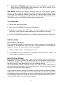
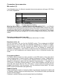
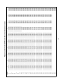
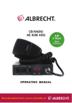
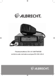
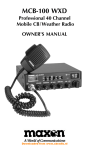
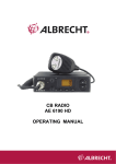
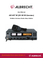
User Manual
AE 497 W (25-30 W-Version)
10-Meter Amateur Radio Base Station
Downloaded from www.cbradio.nl
Legal notes and general information
This amateur radio base station complies to the minimum requirements of the EU directives 2004/108/EG (EMC),
full fills the harmonized EU standards EN 301 783-2 (commercial available amateur radio products , EN 301 489-1
und-15 (EMC) und EN 60950-1:2006 (safety and LVD -directive 73/23/EWG) nad is marked with the CE logo.
Following conditions apply:
In all European countries this transceiver is subject to national amateur radio regulations. It may be used
only by persons, who have obtained a valid amateur radio licence.
Radio amateurs are only allowed to use this radio on assigned amateur radio frequencies within the 10 m
band, even if this radio should be able to switch other adjacent frequencies. National regulations may
exist for environmental RF protection and must be applied by the operator.
It is not allowed to use this radio for any other purpose except amateur radio.
If this radio shall be used in a configuration with other accessory items or amplifiers, the radio amateur is
responsible to keep the radiations within the legal limits of his licence class, especially he has to follow the rules
and standards of the above mentioned EU directive and technical standards, especially EN 301 783-2. It may be
necessary to add separate harmonics filters when combining to amplifiers or SWR meters or antenna switching
devices.
This radio is not declared to be used in cars during motion, because we cannot declare that there is no possible
influence on the electronic engine management. Please respect the automotive directive requirements, which
request that such devices are not allowed to be connected to the car network as long as the car engine is running.
These restrictions are only valid for passenger cars and trucks and do not apply to parking recreation vehicles,
boats or other environments with 12 V power supply.
ALAN ELECTRONICS GMBH
The text of the English manual corresponds to international versions and is not in all parts equal to the German
language user manual.
2
SPECIFICATIONS
GENERAL
Frequency Range …………………………………………………...28.000 to 29.699MHz
Frequency Control ………………………………….Phase Lock Loop (PLL) synthesizer
Frequency Stability………………………………………………………………… ± 300HZ
Frequency Tolerance ………………………………………………………………0.0003%
Emission Mode…………………………………………… A3E(AM), F3E(FM), J3E(SSB)
Microphone ………………Electret type 6 pin plug, with PTT, up/down and coiled cord
Input Voltage …………………………………13.8V DC nominal, 15,9V max. 12.0V min
230V AC
Size (WDH)………………………………………………………………300 x 240 x 85mm
Weight …………………………………………………………………………………..3,4Kg
Antenna Connector…………………………………………. SO-239 50 ohm unbalanced
Speaker……………………………………………………………………….8 ohm, 3 watts
TRANSMITTER
Power Output ……………………AM max. 7-8W, FM 25W-30 W, SSB 25W-30W PEP
Spurious Emission …………………………………..……………….-36 dBm or – 60 dBc
Current Drain No Modulation ……………………………………….FM/AM less than 4 A
SSB …………………………………………………..…without modulation less than 1.0A
Current Drain SSB with Modulation………………………………….SSB less than 4 A
Modulation Frequency Response
(1 KHz, 0dB Reference)……………………….....Lower, at 450Hz, AM -6dB, SSB -6dB
Upper, at 2.5KHz, AM -6dB, SSB -6dB
Microphone Sensitivity …………………………………………..AM 2.mV for 60% mod
FM 1.8mV for 1.5 kHz deviation
Microphone Amplifier ………………….AM 50dB (between 89% and 80% modulation)
SSB 50dB (between 25 W PEP and 10W PEP)
RECEIVER
Max Sensitivity for 6dB S/N………………………………… AM 0.5uV, FM/SSB 0.25uV
Sensitivity for 10dB S/N ……………………………………..AM 0.5uV, FM/SSB 0.25uV
Overload Audio Fidelity at 6dB Down ………………………………….450Hz ~ 2000 Hz
Adjacent Channel Selectivity …………………..………………FM/AM 60dB, SSB 70dB
Image Rejection (5.6MHz) ……………………………………Typically better than 90 dB
IF Rejection …………………………………………………………………..70dB or better
Max Audio Output Power …………………………………………..AM/FM/SSB 2.5 watts
Squelch Range……………………………………………..Adjustable from 0.5Uv to 1mV
Receiver Clarifier Range…………………………………………….…±1.25KHz Variable
Dynamic Range………………………………………………………………… 65dB (SSB)
3
Overview: Knobs and Keyboard functions
1
19
20
21
22
18
17
16
15
14
2
13
12
3
4
5
6
8
7
9
10
11
1. POWER ON/OFF SWITCH
This switch turns the transceiver power on and off.
2. HEAD PHONE JACK
Connect head phone plug, Impedance > 32 Ohms, Mono
3. MICROPHONE INPUT
6 pin socket for Albrecht Standard Electret Hand Microphone
4. VOLUME CONTROL
Controls audio output level
5. SQUELCH CONTROL
Used to quiet the receiver during absence of receive signals
Sensitivity to incoming signals is fully adjustable
6. POWER CONTROL Fine adjusting of the Transmit Output Power, down to 3 W
FM/SSB or 0.5 Watt AM
7. CLARIFIER CONTROL
This control provides an adjustment for turning in stations which are slightly OFF
frequency, to optimise the AM and SSB reception and transmission.
8. RF GAIN & MIC GAIN CONTROL
Control the receiver sensitivity by RF GAIN CONTROL (outer knob) to reduce
interference. To decrease RF gain, turn the knob counter clockwise. For the
maximum receiver sensitivity, the RF GAIN control must be rotated clockwise.
MIC GAIN CONTROL (inner knob)
This control provides the proper or desired modulation.
9. CHANNEL SELECTOR SWITCH
This Rotary switch selects the frequency steps. (Switch not active during
transmission)
4
10. SWR CALIBRATION CONTROL
The calibration control provides (while keying transmitter) meter calibration
adjustment enabling true standing wave ratio reference.
11. CAL/ SWR/ MOD SELECTION
This switch is used to select the scale to be read on the SWR/ Power Meter. The
switch has three positions MOD (Modulation), CAL (Calibrate), SWR (Standing Wave
Ratio)
KEYBOARD switches 12 - 19
Some of these switches have a double or even 3 way functions. Pressing the
FUNCTION knob (17) before lets You select the second function of the key. In some
cases the third function is selected automatically depending on Your logical actions
before.
Primary function is indicated by “FUNCTION OFF:” This means no FUNC button
shall be pressed
Second function is indicated with “ FUNCTION ON: “ This means that You must
press the FUNC button shortly before using the desired button.
•
Third function is always indicated in this way
12. MODE / LOW / MEMORY 5 SWITCH
Double function button: without pressing FUNCTION before:
MODE FUNCTION – select one of the operation modes
FM / AM / USB / LSB
•
Load channel in the memory 5 with MEM switch.
After pressing FUNCTION button before:
LOW FUNCTON – This switch activates tone low (high cut) circuits.
•
Save channel in the 5 with MEM switch.
13. MEMORY SWITCH
FUNCTION OFF:
MEMORY LOAD FUNCTION – Load one of the 5 memory channels with 5 numeric
key.
FUNCTION ON:
MEMORY SAVE FUNCTION – Save one of the 5 memory channels with 5 numeric
key.
5
14. LCR / MEMORY 4 SWITCH
FUNCTION OFF:
LCR (Last Channel Recall) FUNCTION – Press LCR to return to the last channel that
was used for longer than 3 seconds or was transmitted on.
• Load channel in the memory 4 with MEM switch
FUNCTION ON;
• Save channel in the memory 4 with MEM switch
15. CALL / MEMORY 2 SWITCH
FUNCTION OFF:
CALL FUNCTION – This switch is used to access a reprogrammed frequency
(memory 2)
• Load channel in the memory 2 with MEM switch
FUNCTION ON:
• Save channel in the memory 2 with MEM switch
16. DIM SWITCH
FUNCTION OFF:
DIM FUNCTION – This switch is used to switch the instruments and keyboard
illumination from bright to dimmer.
17. FUNC SWITCH
BRIEF PUSH: This switch activates as FUNCTION switch the secondary function of
double function switches.
18. STEP / NB / MEMORY 1 SWITCH
FUNCTION OFF:
STEP FUNCTION – This switch is used for select one of the frequency
between: 1KHz / 10KHz / 100KHz
1KHz:
10KHz:
100 KHz:
•
steps
Sets 1KHz digit of the desired operating frequency.
Sets 10 KHz digit of the desired operating frequency.
Sets 100KHz digit of the desired operating frequency.
Load channel in the memory 1 with MEM switch.
FUNCTION ON:
NB FUNCTION – (Noise Blanker) If your reception is disturbed by interference from
impulse type noise (ignition noise and other electrical noise press NB to reduce or
eliminate the noise)
•
Save channel in the memory 1 with MEM switch.
6
19. SCAN / SHIFT / MEMORY 3 SWITCH
FUNCTION OFF:
SCAN FUNCTION – Set the scan mode on/off in RX mode.
•
Load channel in the memory 3 with MEM switch.
FUNCTION ON:
SHIFT FUNCTION for Repeater operation – Press the shift switch to select the
direction: + SHIFT / -SHIFT. Press more than 3 seconds the SHIFT switch to select
to off-set step: 0 ~ 990KHz. In most countries 100 kHz shift is usual. You can get
more information by the local amateur radio clubs.
•
Save channel in the memory 3 with MEM switch.
20. LCD DISPLAY
LCD indicates the frequency or channels if selected.
21. MOD / SWR ANALOG METER
This meter reflects SWR calibration and modulation, operated in TX mode.
22. S / RF ANALOG METER
In receive mode, this meter displays incoming signal strength. In the transmit mode
this Meter displays RF power.
BEEP/TONE
Turning on power switch while keeping PTT key pressed sets beep mode on/off.
Display Panel Features: Illustrated below are all the VISUAL INDICATORS that
appear on the display, and the corresponding feature function that they associate
with.
Liquid Crystal Display Panel: The liquid crystal panel provides the user with a visual
information on the operation and status of the AE 497 W.
CAUTION: Due to the physical behaviour of LCD’s, liquid crystal displays should not
be subjected to extremes of temperature or humidity. If the unit is exposed to
temperatures below -20°C (-5°F) or above + 60°C ( +140°F), the display may
temporarily cease to function properly, and in some cases, could result in permanent
7
damage. Do not subject radio to extreme conditions, such as closed automobile in
direct sunlight or continuous sub zero temperatures.
All liquid crystal displays have a preferred viewing angle when the display contrast is
at a maximum. The best viewing point will vary by user, depending on such variables
as temperature, humidity, battery condition, and the actual users eyesight.
•
Function ( FUNC) Mode: Indicates that the “FUNC” button has been selected,
which allows for operation of many of the various features.
•
AM: Indicates AM mode operation.
•
FM: Indicates FM mode operation.
•
USB: Indicates Upper Sideband mode operation.
•
LSB: Indicates Lower Sideband mode operation.
•
SCAN: Indicates that the radio is in the “scan” mode which works in
conjunction with all frequency and five memory locations.
•
Frequency Readout: Displays the corresponding frequency associated with
the channel you are communicating with.
•
LOW: Indicates that the Tone Low feature has been turned on.
•
SHIFT: Indicates that the SHIFT (+ and -).
•
NB: Indicates that the Noise Blanker features has been turned on.
•
•
“L”: Indicates that the memory recall ( = Load) mode has been activated
“S”: Indicates that the radio is in the “Memory Store” mode, ready to receive a
channel into one of the memory locations.
•
TX: Indicates that the radio is in the “transmit” mode.
ANALOG INDICATOR METER:
A
A
B
S-TX METER: Indicates relative incoming signal strength and RF out put
power.
8
B
Modulation / SWR Meter: Measures the percent modulation of the AM signal.
Note that the CAL/SWR/MOD switch must be in the “MOD” position for the
meter to measure and read modulation.
SWR METER: Measures the ratios of standing wave ratio of the antenna system,
which is critical in properly adjusting the length antenna and all related electrical
connections. This meter will indicate if there are any major changes in these critical
areas caused by such things as humidity, vibration, or corrosion, which will cause the
SWR Meter to rise. A rising SWR indicates that a problem exists.
To Calibrate SWR:
a) Set the radio into the AM mode.
b) Switch the CAL/SWR/MOD knob to the SWR position
c) Transmit by pressing the PTT button on the microphone, and adjust the
SWR/CAL, control until the needle reaches the CAL position on the meter.
d) Put the CAL/SWR/MOD knob back to the SWR position, and read the SWR value.
INSTALLATION
LOCATION OF THE RADIO
Prior to beginning operation if the transceiver, a basic installation must be prepared.
Installation of the transceiver itself is a rather simple procedure. In selecting the
location for the unit, two basic factors must be considered:
A. Access to 230V, 50Hz or 13,8V DC power source.
B. The location must be convenient for running the antenna lead in cable if an
outside antenna installation is proposed.
BASE STATION ANTENNA
Since the maximum allowable power output of the transmitter may be limited by the
Regulations or Licence classes, the antenna is the most important factor affecting
transmission distance. Only a properly matched antenna will allow maximum power
transfer from the 50 ohm transmission line to the radiating element.
The recommended method of antenna turning is to use the built in SWR meter to
adjust the antenna turning for maximum reflected power. The radio may be used with
any type of 50 ohm base station antenna.
A ground plane vertical antenna will provide the most uniform horizontal coverage.
This type of antenna is best suited for communication with a mobile unit. For point to
point operation where both stations are fixed, a directional beam will usually increase
communicating range since this beam antenna also allows the receiver to “listen” in
only one direction, thus reducing interfering signals.
9
OPERATING PROCEDURES TO RECEIVE
1. Turn the radio ON by pressing the POWER switch.
2. Press the “Mode” selection button (labeled “5” on the button) continuously until
you find the mode of operation you desire to operate in (AM, FM, USB, LSB).
3. Adjust the VOLUME control until you reach your desired listening level.
4. Turn the frequency selector knob to the desired operating frequency.
5. Turn the RF GAIN control completely clockwise.
6. Adjust the “CLARIFIER” control to clarify the SSB signals (start from middle
position).
7. Listen to the background noise coming from the radio. Turn the squelch control
slowly until the noise just disappears. (No signal should now be present). Leave
the control at this setting. The SQUELCH is now properly adjusted. The receiver
will remain quiet until a signal is actually received. Do not advance the knob too
far, as some of the weaker signals will not be heard.
OPERATING PRODEDURE TO TRANSMIT
1. Select the desired frequency of transmission.
2. Set the MIC GAIN control fully clockwise.
3. Activate the press to talk switch. The receiver and transmitter are controlled by
the press to talk switch on the microphone. Press the switch and the transmitter is
activated. Release the switch to receiver.
4. Hold the microphone two inches from your mouth, speak in a clear normal voice.
5. The S-TX meter will indicate power output and the modulation meter will indicate
percentage of modulation as you speak into the microphone.
CAUTION: Be sure the antenna is properly connected to the radio before
transmitting. Transmitting without an antenna or a poorly matched antenna could
cause damage to the transmitter.
RESEIVING SSB SIGNALS
There are four types of signals presently used for communications in the Citizen
Band: AM, FM, USB and LSB. When the MODE switch on your unit is placed in the
AM position, only standard double sideband, fully carrier signals will be detected. An
SSB signal may be recognized while in the AM mode to produce an intelligible
output. The USB and LSB modes will detect upper sideband an lower sideband
respectively, and standard AM signals.
10
SSB reception differ from standard AM reception in that SSB receiver does not
require a carrier or opposite sideband to produce an intelligible signal. A single
sideband transmitted signal consists only of the upper or the lower sideband and no
carrier is transmitter. The eliminate of the carrier from the AM signal helps to
eliminate the biggest cause of whistles and tones heard on channels which make
even moderately strong AM signals unreadable. Also, SSB take only half of an AM
mode therefore two SSB conversations will fit into each frequency, expanding the two
time frequency. The reduction in channel space required also helps in the receiver
because only half of the noise and interference can be received with 100% of the
SSB signal.
An SSB signal may be received only when the listening receiver is functioning in the
same mode. In other words, an Upper Sideband Signal (USB) may be made
intelligible only if the receiver is functioning in the USB position.
If a Lower Sideband (LSB) signal is heard when the receiver is in the USB mode, no
amount of turning will make the signal intelligible. The reason for this may be
understood if you consider that when the modulation is applied to the transmitter`s
microphone in the USB mode, the transmitter`s output frequency is increased
whereas in the LSB mode the transmitter’s output frequency is decreased. The result
in listening to the receiver is that when the MODE switch is in the proper position
(either USB or LSB), a true reproduction of single tone of modulation will result, and if
the tone is increased in frequency (such as a low pitched whistle or a high pitched
whistle) you will hear the increase in the output tone of the receiver. If the incorrect
mode is selected, an increase in tone of a whistle applied to the transmitter will cause
a decrease in the resultant tone from the receiver.
Thus when a voice is used in place of a whistle or a tone, in the proper listening
mode the voice will be translated backwards and cannot be made intelligible by the
voice lock control. When listening to an AM transmission, a correct side band is
heard in either mode since both upper and lower sideband are received. Once the
desired SSB mode has been selected, frequency adjustment may be necessary in
order to make the incoming signal intelligible. The CLARIFIER controls allow the
operator to vary the frequency above and below the exact center frequency of the
received signal. If the sound of the incoming signal is too high or too low pitched,
adjust the CLARIFIER control. Consider it as performing the same function as a
Dictaphone speed control. When the speed is set too high, voices will be high
pitched, and if set too low, voices will be low pitched. Also, there is only one correct
speed that will make a particular tape produce the same sound that was recorded. If
the tape is played on a player that rotates in the wrong direction (opposite sideband),
no amount of speed control (Clarifier) will produce an intelligible sound.
An AM signal received while listening in one of the SSB modes will produce a steady
tone (carrier) in addition to the intelligence, unless the SSB receiver is turned to
exactly the same frequency by the Clarifier control. For simplicity it is recommended
the AM modes be used to listen to AM signals.
11
Connectors for accessories
Mic socket (3)
6 pin Standard plug, for Albrecht standard electret microphones with appr. 600 Ohm
to1 kOhm Impedance:
PIN 1
PIN 2
Mic Audio
PTT-RX contact and Packet-Radio audio
output
PIN 3
PTT-TX contact
PIN 4
UP- / DOWN keys
PIN 5
Common ground, shielding
Warning Notes: We have modified the mic wiring by end of 2008 to our Albrecht
PIN 6
+ supply voltage for mic preamplifiers
Standard hand microphone with up/down key wiring. Please never connect any older
microphone type with additional switches as they had been in use for former versions
of this model (AE 497 S or AE 497WS or older versions of AE 485 S). The former
additional key wiring may damage the PIN 6 power supply wiring inside the new radio
model.
Extension speaker socket (rear side)
3.5 mm Mono- socket for 4- 8 Ohm speakers with at least 2-4 Watt.
Earphone socket (2)
On the front panel You can find the PHONES socket. This is designed for MONO
phones with 6.3 mm mono plug and standard impedances of 32 Ohms or higher.
Stereo headphones can only be connected via adapter Stereo-to-Mono or must be
equipped with a Mono 6.3 mm phones plug. It is not allowed to connect low
impedance headphones ( with 8 Ohms or less), because EU regulations do not allow
any more to use headphones and outputs where a risk of acoustical shocks may
exists.
Programming Modes
For skilled service people we have provided a sub PCB inside of the radio which
allows programming of several special channel configuration modes. Modifications
are only allowed for use in countries where different modes are allowed. While it is
allowed to sell amateur radios with the extended channel system + standard 10 m
VFO mode in Germany (jumper position 2), some other European countries do not
allow this and accept only the 10 m VFO range. In such cases the jumper must be
plugged from position 2 into the position 1 by your distributor before sales. The reset
button must be pressed after reprogramming.
Repair & Service
If any resending for repairs or warranty matters may become necessary for radios sold
in Germany, please contact our hotline by phone. The Hotline will inform you about the
nearest service address.
Customers outside Germany should contact their local distributor.
12
Software procedure for Channel Mode (if enabled) :
•
•
•
Press FUNC and after this press „2/Call“ for longer than 3 seconds
The radio works then in a channelized mode from 25.165 MHz to 29.695 MHz
on 454 channels in 10 bands.
Band switch: Press 2/Call
Toggle between channel number and frequency display:
•
Press FUNC and then 2/CALL shortly.
Frequency Range
28.000-29.699 MHz
Frequenzmode
28.000-29.699 MHz
Frequency Mode +
26.165- 29.695 MHz
channel mode (454
channels)
Function
In some countries
requested
Enabled for sales in
Germany.
Switching via
Function + 2/CALL
(press 3 seconds)
© Alan Electronics GmbH, 2010 – Daimlerstr. 1 k – D- 63303 Dreieich
Technical Hotline:
01805 012204 (only for radios sold in Germany,
14 cents/minute, other charges from mobile networks)
Customers in other countries please contact
the local distributor or point of sale.
Spare parts service:
Fax :
e-mail :
Download-Server:
06103-9481-22
06103-9481-60
[email protected]
www.hobbyradio.de
13
Declaration of Conformity
We hereby declare that our product: 10 m Amateur Radio Transceiver
AE 497 W
satisfies all technical regulations applicable to the product within the scope of EU Council
Directives and harmonized European Standards:
EU- Directives : 73/23/EEC, 2004/108/EG and 99/5 EC ;
European Standards EN 301 489-1 V 1.8.1, EN 301 489-15 V 1.2.1, EN 301 783-2 V.1.1.1,
EN 60 950- 1 : 2006
All essential radio test suites have been carried out.
Alan Electronics GmbH
Daimlerstr. 1 k
63303 Dreieich
GERMANY
This declaration is issued under the sole responsibility of the manufacturer according to the
procedure of Annex III R&TTE directive.
Basing on this declaration, the amateur radio may be used only by authorized persons having a valid amateur
radio licence, and only for the purpose of amateur radio service in the dedicated frequency ranges.
Note: the latest valid issue of this Declaration of Conformity, as well as all other information about this radio and
possible restrictions of use, can be downloaded any time from our public internet server under:
http://www.hobbyradio.de
Contact person:
Wolfgang Schnorrenberg
Place and date of issue:
Lütjensee, den 22. 12. 2009
(Signature)
Dipl.-Phys. Wolfgang Schnorrenberg
Alan Electronics GmbH
14
Channel
number
1
2
3
3A
4
5
6
7
7A
8
9
10
11
11A
12
13
14
15
15A
16
17
18
19
19A
20
21
22
23
24
25
26
27
28
29
30
31
32
33
34
35
36
37
38
39
40
41
42
43
44
25.615
25.625
25.635
25.645
25.655
25.665
25.675
25.685
25.695
25.705
25.715
25.725
25.735
25.745
25.755
25.765
25.775
25.785
25.795
25.805
25.815
25.825
25.835
25.845
25.855
25.865
25.875
25.905
25.885
25.895
25.915
25.925
25.935
25.945
25.955
25.965
25.975
25.985
25.995
26.005
26.015
26.025
26.035
26.045
26.055
25.165
25.185
25.195
25.205
25.215
25. 225
25. 235
25.245
25. 255
25. 265
25.275
25.285
25.295
25.305
25.315
25.325
25.335
25.345
25.355
25.365
25.375
25.385
25.395
25.405
25.415
25.425
25.455
25.435
25.445
25.465
25.475
25.485
25.495
25.505
25.515
25.525
25.535
25.545
25.555
25.565
25.575
25.585
25.595
25.605
B
A
26.065
26.075
26.085
26.095
26.105
26.115
26.125
26.135
26.145
26.155
26.165
26.175
26.185
26.195
26.205
26.215
26.225
26.235
26.245
26.255
26.265
26.275
26.285
26.295
26.305
26.315
26.325
26.355
26.335
26.345
26.365
26.375
26.385
26.395
26.405
26.415
26.425
26.435
26.445
26.455
26.465
26.475
26.485
26.495
26.505
C
26.515
26.525
26.535
26.545
26.555
26.565
26.575
26.585
26.595
26.605
26.615
26.625
26.635
26.645
26.655
26.665
26.675
26.685
26.695
26.705
26.715
26.725
26.735
26.745
26.755
26.765
26.775
26.805
26.785
26.795
26.815
26.825
26.835
26.845
26.855
26.865
26.875
26.885
26.895
26.905
26.915
26.925
26.935
26.945
26.955
D
26.965
26.975
26.985
26.995
27.005
27.015
27.025
27.035
27.045
27.055
27.065
27.075
27.085
27.095
27.105
27.115
27.125
27.135
27.145
27.155
27.165
27.175
27.185
27.195
27.205
27.215
27.225
27.255
27.235
27.245
27.265
27.275
27.285
27.295
27.305
27.315
27.325
27.335
27.345
27.355
27.365
27.375
27.385
27.395
27.405
E
15
27.415
27.425
27.435
27.445
27.455
27.465
27.475
27.485
27.495
27.505
27.515
27.525
27.535
27.545
27.555
27.565
27.575
27.585
27.595
27.605
27.615
27.625
27.635
27.645
27.655
27.665
27.675
27.705
27.685
27.695
27.715
27.725
27.735
27.745
27.755
27.765
27.775
27.785
27.795
27.805
27.815
27.825
27.835
27.845
27.855
F
27.865
27.875
27.885
27.895
27.905
27.915
27.925
27.935
27.945
27.955
27.965
27.975
27.985
27.995
28.005
28.015
28.025
28.035
28.045
28.055
28.065
28.075
28.085
28.095
28.105
28.115
28.125
28.155
28.135
28.145
28.165
28.175
28.185
28.195
28.205
28.215
28.225
28.235
28.245
28.255
28.265
28.275
28.285
28.295
28.305
G
28.315
28.325
28.335
28.345
28.355
28.365
28.375
28.385
28.395
28.405
28.415
28.425
28.435
28.445
28.455
28.465
28.475
28.485
28.495
28.505
28.515
28.525
28.535
28.545
28.555
28.565
28.575
28.605
28.585
28.595
28.615
28.625
28.635
28.645
28.655
28.665
28.675
28.685
28.695
28.705
28.715
28.725
28.735
28.745
28.755
H
Frequency table for AE 497W (only for activated channel-mode)
28.765
28.775
28.785
28.795
28.805
28.815
28.825
28.835
28.845
28.855
28.865
28.875
28.885
28.895
28.905
28.915
28.925
28.935
28.945
28.955
28.965
28.975
28.985
28.995
29.005
29.015
29.025
29.055
29.035
29.045
29.065
29.075
29.085
29.095
29.105
29.115
29.125
29.135
29.145
29.155
29.165
29.175
29.185
29.195
29.205
I
29.215
29.225
29.235
29.245
29.255
29.265
29.275
29.285
29.295
29.305
29.315
29.325
29.335
29.345
29.355
29.365
29.375
29.385
29.395
29.405
29.415
29.425
29.435
29.445
29.455
29.465
29.475
29.505
29.485
29.495
29.515
29.525
29.535
29.545
29.555
29.565
29.575
29.585
29.595
29.605
29.615
29.625
29.635
29.645
29.655
29.665
29.675
29.685
29.695
J