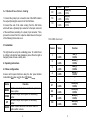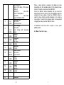
1
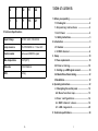
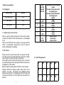
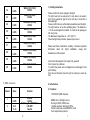
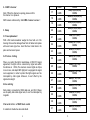
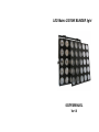
LED Matrix 25X10W BLINDER light
USER MANUAL
Ver1.0
2
7
12
17
22
1
6
11
16
21
Table of contents
1. Before you operating ·······················································2
1.1 Packing list ································································ 2
1. 2 Un p a c k i ng in s t r u c t i o ns ······························ 2
5.Technical Specifications
1.3 AC Pow e r ······························································· 2
Input Voltage
AC100V -240V, 50Hz/60Hz
Lamp resource
25x10W RGBW 4 in 1 Cree LED
Control model
Auto,sound,DMX512 signal
Max temperature
104°F(40°C)
Side size
575x575x90mm
1.4 Safety instructions···················································· 3
2. Introduction ········································································3
2.1 Features ······································································3
2. 2 DM X ch a n n e l ························································4
3. Setup ················································································· 10
3.1Fuse replacement····················································· 10
3.2 Fix t u r e lin k i n g ···················································· 10
3. 3 Setting up a DMX signal connect························10
N.W
14.5kg
3.4 Master/Slave fixture linking···································12
3.5installation··································································· 12
4. Operating instructions····················································12
4.1 Navigating the control panel ···························· 12
4. 2 Me nu fun c t io n map ····································· 13
4.3 Use r co n f ig ur a t i o n s ······································ 14
4. 4 DM X ch a nn e l val u e s ·································· 1 4
4. 5 LE D ran g e m e nt ··············································28
5. Technical specifications················································ 29
16
1
1. Before you operating
31-200
201-225
226-250
251-255
1.1 Packing list
Product name
quantity
LED Matrix Light
1 pcs
Power cable
1pcs
3
User manual
1pcs
4
0-255
0-255
5
1.2 Unp a c k ing in s tr u c ti o ns
When you get this product, please take it from carton carefully
to make sure whether all the accessories are in and damaged
or not
When you find that there are any parts or wrong sign with the
carton, or non-operation, please inform us and to keep the
carton and shipping bill completely.
0-255
6
0-255
7
0-127
128-255
Strobe-effect with increasing
speed
Random strobe mode1 with
increasing speed
Random strobe mode2 with
increasing speed
Neutral
Red
0-100%
Green
0-100%
Blue
0-100%
White
0-100%
Sound Control
No function
Sound control
1.3 AC Pow e r
Please check the manual book before you operate the light.
The rating current of the light listed which shows the average
current-consume under the normal circumstances.
All the lights must be offered shoot-through circuit, it could not
be connected dimmer circuit, although the dimmer channels are
completely for 1-100% switch.
Before the light’s working, please confirm the correct voltage.
Warning! Confirm the voltage to select switch which can be
matched the circuit with the light. If it is different from the
supply power and light, it will damage the light! All the light must
be connected the earth, not all the lights have the switch to be
selected.
2
4. 5 LE D R an ge m e n t :
5
10
15
20
25
4
9
14
19
24
3
8
13
18
23
15
32
33
34
35
36
37
38
39
40
0-255
White(3,8,13,18,23)
0-100%
0-255
Red(4,9,14,19,24)
0-100%
0-255
Green(4,9,14,19,24)
0-100%
0-255
Blue(4,9,14,19,24)
0-100%
0-255
White(4,9,14,19,24)
0-100%
0-255
Red(5,10,15,20,25)
0-100%
0-255
Green(5,10,15,20,25)
0-100%
0-255
Blue(5,10,15,20,25)
0-100%
0-255
White(5,10,15,20,25)
0-100%
7 DMX ch a nn e l s:
1.4 Safety instructions
Please confirm the same voltage to the light.
The light could not be water-proof, it only allow to be used in
door. Don’t expand the light in wet or rain day, to avoid fire or
damaged light.
Please confirm there is no flammable material around the light.
The light must be set up the ventilating place. The distance is
≥51cm around approach material. To check the air passage is
OK at any time.
The Maximum temperature is ≤40℃(104℉).
When the lights has problems, please stop to use to
Please read these instructions carefully, it includes important
information about the light’s installation, usage and
maintenance of this product.
And contact the supplier. Don’t repair it by yourself!
Don’t connect by a dimmer.
To confirm the power wire is straight and non-damaged. Don’t
pull it directly.
Don’t look at the bulb when the light is working to avoid any
hurt.
2. Introduction
2.1 Features
Channel
Value
Function
110/100/40/7 DMX channels.
1
2
0-255
0-10
11-30
Dimmer
0-100%
Switching the LEDs/Strobe
LED OFF
Neutral
14
RGBW 4-in-1 LED light source
life long is 50000-10000 hours.
Variable electronic dimmer(0-100%).
Control mode:Auto,sound,DMX512 mode
Cool: temperature protector
3
2.2 DM X ch a nn e l
0-255
Note: *When the channel is opening, please confirm
the channel 1st is phase-in.
17
18
DMX value is referenced by “4.4 DM X ch a nn e l va l ue s ” .
19
3. Setup
20
3.1 Fuse replacement
With a flat head screwdriver wedge the fuse hold out of its
housing. Remove the damaged fuse from its holder and replace
with exact same type fuse. Insert the fuse holder back in its
place and reconnect power.
21
3.2 Fix tu re li nk in g
22
23
24
When you control the light’s master/slave or DMX 512 signal
agreement, the lights can be connected by signal wire which
the distance is ≤500m,The maximum connect lights are 32pcs
more or less, and adapt DMX light pair to segregate the signal
zoom equipment, in order to protect the light’s signal won’t be
interrupted by other signal. Moreover, it won’t affect by the
signal wire’s length
25
26
27
0-255
0-100%
Red(21,22,23,24,25)
0-100%
Green(21,22,23,24,25)
0-100%
Blue(21,22,23,24,25)
0-100%
White(21,22,23,24,25)
0-100%
0-255
Red(1,6,11,16,21)
0-100%
0-255
Green(1,6,11,16,21)
0-100%
0-255
Blue(1,6,11,16,21)
0-100%
0-255
White(1,6,11,16,21)
0-100%
0-255
Red(2,7,12,17,22)
0-100%
0-255
Green(2,7,12,17,22)
0-100%
0-255
Blue(2,7,12,17,22)
0-100%
0-255
White(2,7,12,17,22)
0-100%
0-255
Red(3,8,13,18,23)
0-100%
0-255
Green(3,8,13,18,23)
0-100%
0-255
Blue(3,8,13,18,23)
0-100%
0-255
0-255
0-255
Dat a ca b li n g
28
Data cable is connected by DMX data wire, and XLR. Please
use hi-quality data cable signal wire, it won’t be interrupted by
magnetic.
Cha r a c te ri st i c s of DMX dat a ca b le
2 conductors’ double tree lace and shield.
4
29
30
31
13
40 DM X ch an n e l s:
Channel
1
2
3
4
5
6
7
8
9
10
11
12
13
14
15
16
Value
0-255
0-255
0-255
0-255
0-255
0-255
0-255
0-255
0-255
0-255
0-255
0-255
0-255
0-255
0-255
Function
Red(1,2,3,4,5)
0-100%
Green(1,2,3,4,5)
0-100%
Blue(1,2,3,4,5)
0-100%
White(1,2,3,4,5)
0-100%
Red(6,7,8,9,10)
0-100%
Green(6,7,8,9,10)
0-100%
Blue(6,7,8,9,10)
0-100%
White(6,7,8,9,10)
0-100%
Red(11,12,13,14,15)
0-100%
Green(11,12,13,14,15)
0-100%
Blue(11,12,13,14,15)
0-100%
White(11,12,13,14,15)
0-100%
Red(16,17,18,19,20)
0-100%
Green(16,17,18,19,20)
0-100%
Blue(16,17,18,19,20)
0-100%
White(16,17,18,19,20)
12
The maximum capacitance of the conductors-30 pF/ft.
The maximum capacitance of the conductor and shield -55
pF/ft.
The maximum resistance is 20 ohms/1000ft.
The nominal impedance 100-140 ohms.
DMX opt coupler segregate signal zoom equipment’s 3 pin/5
pin XLR plug.
3-P in to 5- P in con v e r s i on cha r t
Note! If you use a controller with a 5 pin DMX output connector.
you will need to use a 5pin to 3 pin adapter
CHAUVET Model No:DMX5M. Or DMX 5F
The chart below details a proper cable conversion:
3.3
Setting up a DMX signal connect
As following pictures show, please connect the first light to the
signal cable which is with XLR by DMX controller, then, connect
light in series.
5
0-255
3.4
Ma s te r /S la v e fi xt u r e li nk i n g
1.Connect the (male) 3 pin connector side of the DMX cable to
the output (female)3pin connector of the first fixture.
2.Connect the end of the cable coming from the first fixture
which will have a (female)3 pin connector to the input connector
of the next fixture consisting of a (male) 3 pin connector. Then,
proceed to connect from the output as stated above to the input
of the following fixture and so on.
108
109
110
0-255
0-255
0-255
0-100%
Green(25)
0-100%
Blue(25)
0-100%
White(25)
0-100%
10 0 DM X ch a nn e l s:
3.5 installation
Channel
The light must be set up the ventilating place. To confirm there
is nothing to hinder the heat dissipation place. When the light is
hanged, please choose a safety wire.
2
4. Operating instructions
3
4.1 Menu configurations
Access control panel functions using the four panel buttons
located directly under near the the LCD Display.
Button
MENU
DOWN
UP
ENTER
1
Function
Used to access the menu or return to a previous
menu option.
Scrolls through menu options in descending
order.
Scrolls through menu options in ascending
order.
Used to select and store the current menu or
option within a menu.
6
4
...
97
98
99
100
Value
Function
Red(1)
0-100%
Green(1)
0-100%
Blue(1)
0-100%
White(1)
0-100%
...
...
Green(25)
0-100%
Green(25)
0-100%
Blue(25)
0-100%
White(25)
0-100%
0-255
0-255
0-255
0-255
...
0-255
0-255
0-255
0-255
11
4
5
6
7
8
9
10
11
12
13
14
...
107
0-2
3-255
0-2
3-255
0-255
0-255
0-255
0-255
0-127
128-255
0-255
0-255
0-255
0-255
...
100%-0White:0
Red: 0-100% Blue: 100% Green:
0White:0
Red:100%
Blue:100%
Green:0-100%White:0
Red:100%
Blue:100%
Green:100%White:100%
Auto Mix Color
No function
From slow to fast
Color Change
No function
Color change with increasing
speed
Red(All)
0-100%
Green(All)
0-100%
Blue(All)
0-100%
White(All)
0-100%
Sound Control
No function
Sound control
Red(1)
0-100%
Green(1)
0-100%
Blue(1)
0-100%
White(1)
0-100%
...
...
Green(25)
10
When a menu function is selected, the display will show
immediately the first available option for the selected menu
function. To select a menu item, press<ENTER>.
Press the <MENU> button repeatedly until you reach the
desired menu function. Use the <UP> and <DOWN> buttons to
navigate the menu options. Press the <ENTER> button to
select the menu function currently displayed, or to enable a
menu option. To return to the previous option or menu without
changing the value, press the <MENU> button.
No alternative worth that return re-option or menu, press
(MENU) button
4.2 Me nu fun c t io n ma p
7
master, ensure lights under this group without connection with
any DMX controller.
4. 3 Us er con fi g u r at i o n s
Set-up 1pcs light`s menu mode (Auto-running)
.Press the MENU, such as the picture 4.2 shows the menu
function
.Use the UP/DOWN buttons to choose the right one to confirm.
Set-up Master-slave mode
Press the MENU, same as picture 4.2 shows the menu function
Master: Set any one of lights to auto 、sound or strobe control
mode
Set-up DMX mo de
The light can connect to the DMX controller to receive its signal
indication, which control by DMX controller. DMX value is
referenced by “4.4 DM X ch a nn e l va l ue s ” .
4.4 DMX cha n n e l va l ue s
11 0 DMX ch a n n e l s:
Channel
1
0-255
2
3
Slave: Set them to DMX mode and their address code to1.
Notes :Each Master-slave group can be one and only light in
8
Value
0-10
11-30
31-200
201-225
226-250
251-255
0-2
3-41
42-83
84-125
126-167
168-209
210-251
252-255
Function
Dimmer
0-100%
Switching the LEDs/Strobe
LED OFF
Neutral
Strobe-effect with increasing
speed
Random strobe mode1 with
increasing speed
Random strobe mode2 with
increasing speed
Neutral
Mix Color
No function
Red:
100%
Blue:
0
Green:0-100%White:0
Red:
100%-0
Blue:
0
Green:100%White:0
Red:
0
Blue:0-100%
Green:100%White:0
Red: 0 Blue: 100% Green:
9