1
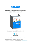
Leader in Electrics & Automation
Tri-MEC
Ring Main Units
Medium Voltage Secondary Distribution
Ring Main Units Up to 24kV, SF6-Insulated
Electric Equipment
Ring Main Units
Technology
Safety
Durability and usefulness
Saving Cost
CONTENTS:
Medium Voltage
Secondary Distribution
Ring Main Units
Up to 24kV,
SF6-Insulated
Applications
4
Features
5
Configurations
6
Modules
8
Ring switch module (RPL)
8
Fuse-switch module (RPF)
9
Circuit breaker module (RVB)
Outer assembly
10
11
RPS
11
RPF
12
RPL
13
RVB
14
RBR
15
Cable termination
16
Ring switch / Circuit breaker
16
Fuse-switch
16
Pannel connection
18
Accessories
19
Installation
24
Technical data
25
Quality assurance
26
Ring Main Units
Applications Tri-MEC
Tri-MEC is designed for use in the following
applications:
•Compact secondary substations
•Small industries
•Wind power plants
•Hotels, shopping centers, office buildings, business centers etc.
•Light mining applications, airports, hospitals, tunnels and underground railways
Generation Transmission
Distribution(24kV)
Substation
Transmission
line
Power plant
Note)
4
Application range.
Commercial &
Industrial
customers
Features
Technology
•Metal enclosed unit for indoor installation and type tested.
•Insulated by SF6 Gas
•Independent of climate.
•ON-OFF-EARTH, three position load break switch.
Safety
•Approachable and operable safely in the presence of power in the cables.
•Clear indication of operation status via mimic diagram on front panel.
•Fully automatic interlocking system.
•Voltage detector to check the presence of voltage in the cable.
Durability and usefulness
•Metal enclosed tank is hermetically sealed, it means this is independent of
environmental effects such as dirt, small insects, and moisture and so on.
•Load break switch operating is possible in the front of Ring Main Units.
•All switching operations can be made safely to personnel because of interlocking
system that operates automatically according to the switch position by the operator.
•Remote operation available in case of using motor mechanism.
•Fuse LBS will be tripped by a fuse striker pin connected to the mechanism
in the event of fault happening.
•Individual panels and panel blocks can be freely combined and extended.
Saving cost
•Only a little maintenance is required except replacement of HRC Power fuse after installation.
•Compact design that requires minimum space to install and operate locally is
main advantage especially where the space is limited.
•Materials can be recycled after the end of its service life.
5
Ring Main Units
Configurations
General
Tri-MEC RMU is an extensible and non-extensible ring main unit for the secondary distribution
network. Tri-MEC RMU can be supplied in various different configurations suitable for most
switching applications in 24 kV distribution networks.
When combined with the Tri-MEC RMU, they represent a complete solution for 24kV
secondary distribution networks. Tri-MEC RMU is a completely sealed system with a stainless
steel tank, gas tight metal enclosure, containing all the live parts, Switching-disconnector, earth
switch, Fuse switch, the circuit breaker.
A sealed steel tank filled with SF6 gas ensures a high level of reliability as well as safety and a
maintenance-free system. The Tri-MEC RMU offers the user a choice of either a switchdisconnector combined with fuse or circuit breaker with relay for protection of the transformer.
Tri-MEC RMU can be controlled completely with an feeder remote unit. Most of this switchgear
exists in version that are extensible on the right or on both sides, in order to provide for future
development.
Information of model name
P: Puffer
V :V.I
B: Bus
D: Double feeder
U: Upside down
R
L: LBS
F: Fuse
B: Breaker
RMU
R: Rising
S: Standard
Non-Extensible type
RPS
<2 LBS + 1 Fused LBS>
LBS
VD
LBS
1535
LBS
VD
Fuse
1502
706
Weight: 400kg
RPF(1R1F)
<1 Fused LBS + Bus rising>
S
LBS
1537
*
VD
695
Fuse
SA
*
1061
706
880
Note) *: Option
6
Weight: 275kg
Configurations
Extensible type
RPL
<LBS Panel>
1750
LBS
VD
0
456
73
Weight: 210kg
RPF
<Fused switch Panel>
S
LBS
1750
*
683
Fuse
611
730
765
Weight: 275kg
RVB
VCB
Trip
2×CT
OC
1750
<Circuit Breaker Panel>
*
730
520
RBR
Weight: 260kg
683
1750
<Bus Rising Panel>
VD
456
730
765
Weight: 160kg
Note) *: Option
7
Ring Main Units
Modules
Ring switch module (RPL)
LBS
VD
< ON position >
EARTHING
EARTHING
SWITCH
LOAD BREAK
LOAD
SWITCH
< OFF position >
EARTHING
EARTHING
SWITCH
LOAD BREAK
LOAD
SWITCH
< EARTH position >
EARTHING
EARTHING
SWITCH
LOAD BREAK
LOAD
SWITCH
Open
Open
Open
Open
Open
Open
Earth
Ear
th
Close
Earth
Ear
th
Close
Earth
Ear
th
Close
Feature
•Three position load break switch and earthing switch.
•Indicator of switch position for load break switch and earthing switch.
•Voltage indicator lamp on panel makes it possible to check the presence of voltage in the cables.
•Pressure gage indicates status of SF6 gas tank and make it check leakage of gas.
•Intelligent interlock system
: To switch to Earth position, it should pass "OFF" position from "ON" position
•Applied high-speed rotary puffer type for extinction of arc.
•Dead front structure: It prevents an accident of touching because the live part is not exposed.
•Electrical (Remote/Local)operation :
operated by controller which can communicate with FRU (Feeder Remote Unit)
•Busbars, 630A
8
Fuse-switch module (RPF)
A
*
LBS
S
B
Fuse
C
Note) *: Option
< ON position >
< OFF position >
< EARTH position >
A
B
B
Close
Close
Open
Earth
Ear
th
EARTHING
EAR
THING SWITCH
Close
Open
Open
FUSE SWTICH
C
FUSE SWTICH
Open
Earth
Ear
th
EARTHING
EAR
THING SWITCH
Open
FUSE SWTICH
Open
Earth
Ear
th
EARTHING
EAR
THING SWITCH
Feature
•Fuse rating: 24kV, Max 63A HRC power fuse
•Indicator of switch position for load break switch and earthing switch
•The Fuses conforming to DIN 43625 are used.
•Automatically tripped to protect from fault current when a fuse is blown
•Applied high-speed rotary puffer type for extinction of arc.
•Dead front structure: It prevents an accident of touching because the live part is not exposed.
•Busbars 200A
•Option: CTD (Condensor Trip Device)
9
Ring Main Units
Modules
Circuit breaker module (RVB)
VCB
Trip
2×CT
OC
*
Note) *: Option
< ON position >
Mechanism operation time
Feature
•200A vacuum circuit breaker
•Rated breaking time: 3cycle
•Latched mechanism - close and open coil
•Protection as specified by customers
•Motor charge type and Manual charge type
•Option:CTD(Capacitor Trip Device), OCR
10
< OFF position >
< Spring charge
indicator >
Outer assembly(Non-Extensible)
RPS (2LBS + 1Fuse-switch)
⑱
❽
❶
❾
❷
❿
❸
⑪
❹
⑫
❺
⑬
❻
⑭
⑮
❼
⑯
LBS
VD
LBS
Fuse
LBS
VD
⑰
❶ LBS operation part
❼ Cable clamp
⑬ Fuse strike link
❷ Chamber
❽ Nameplate
⑭ 200A bushing
❸ Control connector
❾ Gas pressure gauge
⑮ Straight connector
❹ Fixing bolt for cover
❿ Voltage detector
⑯ Earth lug
❺ 630A bushing
⑪ Fuse holder Body
⑰ Earth busbar
❻ Elbow connector
⑫ Fuse holder cap
⑱ Lift lug
11
Ring Main Units
Outer assembly(Extensible)
RPF (Fuse-switch)
❶
⑲
❼
❺
⑭
❷
⑮
❿
❾
⑯
⑰
❸
⑫
❹
⑪
⑬
❽
❻
⑱
S
LBS
Fuse
12
❶ 630A bushing for connector
❽ Earth connection hole
⑮ Pressure switch(option)
❷ Chamber
❾ Gas pressure gauge
⑯ Nameplate
❸ Fuse holder body
❿ Control connector
⑰ Fixing bolt for cover
❹ 200A bushing
⑪ Cable clamp
⑱ Earthing busbar
❺ Operating mechanism
⑫ Fuse holder cap
⑲ Lift lug
❻ Straight connector(Option)
⑬ Fuse strike link
❼ Upper side cover
⑭ CTD(option)
RPL (Ring switch)
❶
⑭
❼
⑪
❸
❽
❾
❷
❿
❹
⑫
❺
❻
⑬
LBS
VD
❶ 630A bushing for connector
❻ Earth connection Hole
⑪ Gas pressure gauge
❷ 600A bushing
❼ Upper side cover
⑫ Fixing bolt for cover
❸ Chamber
❽ Operation mechanism
⑬ Earthing busbar
❹ Elbow connection (option)
❾ Nameplate
⑭ Lift lug
❺ Cable clamp
❿ Voltage detector
13
Ring Main Units
Outer assembly(Extensible)
RVB (Circuit breaker)
❶
❼
❽
❾
❻
❸
⑫
⑪
❹
❷
❺
❿
⑬
VCB
2×CT
Trip
OC
*
Note) *: Option
14
❶ 630A bushing for connector
❻ Gas pressure switch (Option)
⑪ Voltage detector
❷ 630A bushing
❼ Upper side cover
⑫ Gas pressure gauge
❸ Chamber
❽ Operation mechanism
⑬ CT
❹ Elbow connection (Option)
❾ Gas filling valve
❺ Cable clamp
❿ Nameplate
RBR (Bus rising)
❻
⑫
❶
❽
❼
❸
⑪
❷
❾
❺
❹
❿
❶ 630A bushing for connector
❺ Earthing busbar
❾ Voltage detector
❷ 630A bushing
❻ Upper side cover
❿ Cable clamp
❸ Chamber
❼ Gas pressure gauge
⑪ Fixing bolt for cover
❹ Elbow connection (Option)
❽ Nameplate
⑫ Lift lug
VD
15
Ring Main Units
Cable termination
Ring switch / Circuit breaker (ANSI/IEEE Std. 386)
These connectors are designed for easy installation on extruded shield cable or metallic tape shielded cab. The connector
range is from 1/0 to 1000 kcmil for aluminum and copper conductors with insulation diam from o.640" to 1.935".
❻
❼
❿
❽
❸
❾
❺
❹
❶
❶ Stress relief adapter
❹ Grounding eye
Molded rubber adapter is sized to the cable insulation and
provides stress relief for the terminated shield. The radial
pressure exerted on the cable shield by the stress surface.
Suitable for installation on both extruded-surface. Suitable
for installation on both extruded-shield cable and tape-type
shield cable.
❷ Spade terminal
Semi-permanent, crimped-bolted connector sized for the
specific conductor. Crimped on with standard tools and
dies, Also used in the 650Y splice.
❸ Molded conductive shield
Outer jacket of 1/8 think molded conduction peroxidecured EPDM provides a virtually in destructible ground
shield for true dead-front construction. A patented ELASTIMOLD feature.
❽ Interference fit
Hole provides a convenient point to connect a ground wire
to the molded conduction shield, placing the molded shield
at ground potential.
❺ Wrap-around conductive inserts
Inner shield of molded conductive peroxide-cured EPDM
precludes subjecting entrapped air to electrical stress. A
patented ELASTIMOLD feature.
❻ Voltage test point cap
Molded insulating peroxide-cured EPDM exerts uniform
con-centric-pressure on insulation of mating parts to
provide required creep-path length and watermeal.
❾ Apparatus bushing
Epoxy product normally supplied on manufacturers
equipment. Can be welded or clamped to the apparatus.
❿ Threaded stud
Molded conduction rubber cap fits over the test point and
onto the connector housing.
A removable threaded stud is included with every 655LR
and K655LR.
❼ Voltage test point
The 1 hex nut located on the top of the insulation plug
allows the circuit to be tested without disturbing the
connection. The nut is fully insulated from the conductor
and pick up capacitance voltage. A torque wrench with a 1
hex socket attachment is required during installation.
Fuse-switch
16
Grounding eye
Cable
"A"
Straight receptacle housing
Conductor contact
Molded conductive insert
The straight receptacles are fully-shield, fully-submersible and separable insulated connectors. These will accommodate
conductor sizes of No. 4 solid through 4/0 stranded and cable insulation diameters from 0.495" through 0.985".
Bushing
for load
side
Bail
tip
Wire
Straight
receptacle
Bail
Nut
Bail plate
Cable termination
1 way
1 way with SA
2 way
2 way with SA
24kV cable termination selection table
Company
Voltage class
Current
Description
Model number
Power distribution
K655BIP
connectors
K650CP
K655BLR
Elastmold
(PYUNGIL Co., Ltd)
EUROMOLD
24kV
600A
K650ETP
24kV
200A
Straight receptacles
K151SR
600A
Tee connector
K400TE
5815-S
5815-T
3M
24kV
600A
Modular splicing kit
5815-D
5815-E
5815-B
DT625, 635
Cooper power
system
24kV
600A
Bol-T connector
DIP625AS, 635AS
CC6A-U
CA625, 635
*SA: Surge Arrestor
17
Ring Main Units
Pannel connection
Electrical connection with special connectors
Plug
Clamping bolt
Washer
Spacer
End connector
Cross connector
Mold cable
Bushing
Mechanical Joint Panel to Panel
18
Accessaries
Fuse
Features
1. The LS HRC Power Fuses belong to the PRIME MEC
series.
It interrupts high currents before the peak value and
therefore cuts down the required withstand capacity of
the associated equipment on the electric system.
2. Though small in size, it has a high breaking capacity and
its enclosed type is suitable for use inside of the panel
board.
3. PRIME-MEC fuses are equipped with striker pins for
trip indicators as well as for inflicting impulse to trip
link of related load break switches.
Selection of fuses: According to IEC 60787(24kV)
Power Fuse rated current(A)
Transformer rating capacity (kVA)
5
36-75
10
75-157
20
172-358
30
258-538
40
464-965
50
598-1246
63
745-1554
Note) Please ask fuse maker for optimum selection of fuses.
Power fuse characteristic curve
Pre-arcing time-current characteristics
1000
800
600
5A
200A
400
400
10A
160A
200
200
20A
125A
100
80
60
30A
100A
40A
75A
50A
63A
160A
40
100A
0.4
Prospective breaking current(rms:kA) →
40
100
20
6
8
10
2
4
0.01
0.6
0.8
1
0.02
0.01
0.2
0.04
0.02
0.4
0.04
0.06
0.08
0.1
0.2
0.1
0.08
0.06
0.04
0.2
0.1
0.08
0.06
4000
5A
0.4
2
1
0.8
0.6
6000
8000
10000
10A
2000
20A
1
0.8
0.6
4
400
30A
2
10
8
6
600
800
1000
40A
50A
200
63A
4
40
10
8
6
20
60
80
100
75A
Operating time(sec.) →
20
20
125A
4
40
6
8
10
200A
2
100
80
60
0.02
Cut-off current(peak value:kA) →
Cut-off characteristic
1000
800
600
Prospective breaking current (rms:A) →
19
Ring Main Units
Accessaries
Vacuum Interrupter
Current path
Driving force
on the high
current ARC
ARC
Figure 1. Current flow and driving
force on arc for spiral
contact
(ⅰ) Weld
(ⅱ) Bridge explosion
In the closed position, normal current flows
through the interrupter. When a fault occurs
and interruption is required, the contacts are
quickly separated.
The arc drawn between the surfaces of
contacts is rapidly moved around the slotted
contact surface by self induced magnetic
effects, preventing gross contact erosion and
the formation of hot spot on the surface.
The arc burns in an ionized metal vapor,
which condenses on the surrounding metal
shield. At current zero the arc extinguishes
and vapor production ceases.
The metal vapor plasma is very rapidly
dispersed, cooled, recombined, and deionized,
and the metal vapor products are quickly
condensed so that the contacts withstand the
transient recovery voltage.
(ⅰ) Contact jets
(ⅱ) Shield involvement
High current arc mode
Arc initiation
(ⅰ) Arc instability
(ⅱ) Interruption
Current
zero
Fault
current
Time (ms)
Time (㎲)
Voltage Phenomena
(ⅰ) Arc reignition
(ⅱ) Restrikes
(ⅲ) B. I. L
(ⅳ) AC voltage
withstand
Recovery
voltage
Figure 2. AC arcing and interruption phenomena in vacuum.
20
Relay
GIPAM
•LS Integrated Protection and Metering Device
•Integrating the other panel meter, protection relay, control
switch on GIPAM
•Option
- Transducer function
- Sequence of event
•Special Features
- Simplication of the equipments
- Various display function
- Various protection function & easy event analysis
- Data communication function
- High reliability with self-diagnosis function
DPR
•LS high performance Digital Protection Relay
•Various unit types
OCR, OCR/OCGR, OVR(UVR), OVR/UVR, OVGR, SGR
•Effective mutual back-up protecting. Setting range of time
and current is wide and subdivided.
•Fault Recording function and SOE(Sequence of Event)
function provides quickly accurate information to user that is
used in analyzing causes of fault.
•High speed data communication by I-NET communication
method, completely interface with SCADA
Protection/monitoring
Three-phase overcurrent
Zero-sequence overcurrent
Code
Devices
GIPAM
50-51
○
50N-51N
○
DPR-011S DPR-111S DPR-211S DPR-311S DPR-411S DPR-511S
○
○
○
67G
○
Overvoltage
59
○
○
○
Undervoltage
27
○
○
○
59N
○
Selective zero-sequence overcurrent
Zero-sequence overvoltage
Measuring
○
○
○
21
Ring Main Units
Accessaries
Current transformer
Max. system voltage
kV
0.6
Primary current
A
100
Secondary current
A
5
VA
10
Rated burden
Accuracy class
10P10
Short time current
kA/1s
16
Rated frequency
Hz
60
Polarity
Subtractive
Surge arrester
The 273ESA Elbow Arrester is combined with a loadbreak elbow connector interface.
Stud bolt
Surge arrester
Bushing
Bushing insert
Probe
Shelded elbow
Spade terminal
Grounding eye
Cable adapter
Ground lead
Cable
Protective characteristics
Note1)
Duty cycle
Maximum discharge voltage (kV crest)
×20 microsecond current wave
8×
(kVrms)
1.5kV
3kV
5kV
10kV
20kV
F.O.W. protective
level
(kV crest) Note2)
25kV
8.4
10
30.5
32.5
34.5
38.5
43.5
38.5
class
10.2
12
40.0
42.5
45.0
50.0
56.5
50.0
12.7
15
48.0
51.0
54.0
60.0
68.0
60.0
15.3
18
56.5
60.0
64.0
71.0
80.5
71.0
17.0
21
65.5
69.5
74.0
82.5
93.0
82.5
MCOV
(kVrms)
rating
Note) 1. MCOV- Maximum Continuous Operation Voltage.
2. The front of wave (FOW) protective level is the maximum discharge for a 5kA impulse current wave producing a voltage
wave cresting in 0.5 microseconds.
22
CTD (Condenser trip device)
(For discharge)
AC input
DC output
CTD is built as standard in the contactor with
AC control of instantaneous excitation so that
the contactor can be tripped within 30 seconds in
the event of an electricity failure. The automatic
trip circuit in the event of an electricity failure is
to be built by a customer.
Rating
Description
Type
CTD-100
CTD-200
Rated input voltage(V)
AC 100/110
AC 200/220
50/60
50/60
140/155
280/310
Within 5 sec.
Within 5 sec.
Max. 30 sec.
Max. 30 sec.
Input voltage range
85%~110%
85%~110%
Capacitor rating(μ
F)
400
160
Frequency(Hz)
Rated impulse
voltage(V)
Charging time
Trip command
possible time
Control circuit diagram
Terminal
Closing coil (C)
Shunt coil (TC)
The coil operated only when the power is applied
continuously over 45ms. It has built-in electrically antipumping circuit.
When the VCB is 'ON' position, even though the control
power of a shunt coil is 'OFF', the VCB maintains the 'ON'
position.
Rated voltage
Rated current (A)
Rated voltage
Rated current (A)
DC 24V
10
DC 24V
10
DC 110V
2.5
DC 110V
2.5
Note 1) Range of the normal operating voltage: 85~110%
2) DC 24V is the underdeveloped rating.
Control connector
Voltage detector
Screw type
09
11
08
19
10
07
18
06
17
03
05
02
14
04
01
13
Plug in type
12
GAS pressure gauge
Note 1) Range of the normal operating voltage: 70~110%
2) DC 24V is the underdeveloped rating.
23
Ring Main Units
Installation
R = 10D
D : Cable diameter
RPS
RVB + RPL + RBR
77
1348
12-Ø16
Mounting hole
77
607
466
327
524
327
RPF
90.5
102
RPL, RBR
6-Ø18
Mounting hole
377
144
315
144
RVB
4-Ø18
Mounting hole
4-Ø16
Mounting hole
607
607
315
70.5
315
61.5
70.5
61.5
303.5
24
470
61.5
70.5
315
61.5
102
607
40
120
626
120
418×38
Mounting hole
Technical data
Installation type
Indoor type
Rated voltage up to
kV
24
Rated current
A
630 A
Rated current (RVB,RPF)
A
200
Rated power frequency
Hz
50 / 60
Rated short current
kA/1s
16
Rated making current
kA
41.6
Power frequency withstand voltage
kV
50
Rated impulse withstand voltage
kV
125
Operation type
electromotion / manual
Operating voltage
V
DC 110
Operating voltage (CTD Input)
V
AC 110
Insulation material
SF6 Gas
Rated filling pressure (20 °C)
Mpa.
0.034 (5 psi.G)
Minimum operating pressure (20 °C)
Mpa.
0.014 (2 psi.G)
Transfer current (RPF)
A
800
Electrical life
E3
Electrical life (RVB)
E1 , C1
Mechanical life
M1
Standard
IEC 60265-1, IEC 60420
Standard (RVB)
IEC 62271-100
25
Ring Main Units
Quality assurance
Certified quality: KEMA, ISO 9001, ISO 14001
LS Industrial systems has integrated a functional organization into each of its units, the main
purpose of which is to check quality and ensure the adherence to standards.
Routine quality check
While producing Tri-MEC RMU, various routine tests are taken for product capacity, which
testing items are as shown follows.
•Filling pressure check
•Tightness check
•Opening and closing speed measurement
•Dielectric check
•Contact resistance check
Seismic tests
Application standard: JEAG5003-1999
26
Test
category
Norminals
excitation level(g)
X/Y/Z
Direction
Freq.(Hz)
Waveforms Duration(S) Operability
Structural
integrity
Resonance
search
0.1/0.1/0.1
test
X
Y
Z
0.5-30
Random
328
N/A
N/A
Real
earthquake 0.3/0.3/0.15
test
XYZ
Kobe
Earthquake
82
OK
OK
Sine
Wave
30
Waves
OK
OK
OK
OK
OK
OK
OK
OK
OK
OK
OK
OK
OK
OK
OK
OK
OK
OK
OK
OK
OK
OK
OK
OK
Random
328
N/A
N/A
12
RT
Sine 30
waves test
0.3/0/0
0.3/0/0.15
0/0.3/0
0/0.3/0.15
0.3/0/0
0.3/0/0.15
0/0.3/0
0/0.3/0.15
0.3/0/0
0.3/0/0.15
0/0.3/0
0/0.3/0.15
Resonance
search
0.1/0.1/0.1
test
X
XZ
Y
YZ
X
XZ
Y
YZ
X
XZ
Y
YZ
X
Y
Z
5
10
37.8
12.2
0.5-30
Ordering Information
LGS
LS Ring Main Unit
Switch type
R
R
M
24
6
Rated Current
2
200A
6
630A
RPF, RPL, RPS,
RVB, RBR
M Automatic
B
Manual
Rated Voltage
24 25.8(24)kV
Cable connection type
D
M
Rated impulse
withstand voltage
Operating type
12
125kV BIL
D
Dead Break Type
Dead Break &
Plug-in Type
Switch and circuit type
21
1L
1F
2L-1F (RPS)
1 LBS (RPL)
1Fuse-Combination
LBS (RPF)
1R
Bus Rising (RVR)
1V
1VCB (RVB)
21V
2L-1VCB (RVS)
27
Leader in Electrics & Automation
� For your safety, please read user's manual thoroughly before operating.
� Contact the nearest authorized service facility for examination, repair, or adjustment.
� Please contact qualified service technician when you need maintenance.
Do not disassemble or repair by yourself!
Safety Instructions
� Any maintenance and inspection shall be performed by the personnel having expertise concerned.
www.lsis.biz
� HEAD OFFICE
Yonsei Jaedan Severance Bldg., 84-11, Namdaemunno 5ga,
Jung-gu, Seoul, 100-753, Korea
Tel. (82-2)2034-4870
Fax. (82-2)2034-4713
� Global Network
�LS Industrial Systems (Middle East) FZE �
�Dubai, U.A.E.
Address: P.O.Box-114216, API World Tower, 303B, Sheikhe Zayed Road, Dubai, U.A.E.
Tel: 971-4-332-8289 Fax: 971-4-332-9444 e-mail: [email protected]
�Dalian LS Industrial Systems Co., Ltd. �
�Dalian, China
Address: No.15, Liaohexi 3-Road, Economic and Technical Development zone, Dalian 116600, China
Tel: 86-411-8273-7777 Fax: 86-411-8730-7560 e-mail: [email protected]
�LS Industrial Systems (Wuxi) Co., Ltd. �
�Wuxi, china
� CHEONG-JU PLANT
Cheong-Ju Plant #1, Song Jung Dong, Hung Duk Ku,
Cheong Ju, 361-720, Korea
Address: 102-A , National High & New Tech Industrial Development Area, Wuxi, Jiangsu,214028, P.R.China
Tel: 86-510-8534-6666 Fax: 86-510-522-4078 e-mail: [email protected]
�LS-VINA Industrial Systems Co., Ltd. �
�Hanoi, Vietnam
Address: Nguyen Khe - Dong Anh - Ha Noi - Viet Nam
Tel: 84-4-882-0222 Fax: 84-4-882-0220 e-mail: [email protected]
�LS Industrial Systems Tokyo Office �
�Tokyo, Japan
Address: 16FL, Higashi-Kan, Akasaka Twin Tower 17-22, 2-chome, Akasaka, Minato-ku Tokyo 107-8470, Japan
Tel: 81-3-3582-9128 Fax: 81-3-3582-2667 e-mail: [email protected]
�LS Industrial Systems Shanghai Office �
�Shanghai, China
Address: Room E-G, 12th Floor Huamin Empire Plaza, No.726, West Yan'an Road Shanghai 200050, P.R. China
Tel: 86-21-5237-9977 (609) Fax: 89-21-5237-7191 e-mail: [email protected]
�LS Industrial Systems Beijing Office �
�Beijing, China
Address: B-Tower 17FL.Beijing Global Trade Center B/D. No.36, BeiSanHuanDong-Lu, DongCheng-District,
Beijing 100013, P.R. China
Tel: 86-10-5825-6025,7 Fax: 86-10-5825-6026 e-mail: [email protected]
�LS Industrial Systems Guangzhou Office �
�Guangzhou, China
Address: Room 1403,14F,New Poly Tower,2 Zhongshan Liu Road,Guangzhou, P.R. China
Tel: 86-20-8326-6764 Fax: 86-20-8326-6287 e-mail: [email protected]
�LS Industrial Systems Chengdu Office �
�Chengdu, China
Address: 12Floor, Guodong Buiding, No52 Jindun Road Chengdu, 610041, P.R. China
Tel: 86-28-8612-9151 Fax: 86-28-8612-9236 e-mail: [email protected]
�LS Industrial Systems Qingdao Office �
�Qingdao, China
Specifications in this catalog are subject to change without notice due to
continuous product development and improvement.
2008. 01
Address: 7B40,Haixin Guangchang Shenye Building B, No.9, Shandong Road Qingdao 26600, P.R. China
Tel: 86-532-8501-6568 Fax: 86-532-583-3793 e-mail: [email protected]
Ring Main Units(E) 2003. 06/(06) 2008. 01 Printed in Korea STAFF